2003 NISSAN ALMERA N16 torque
[x] Cancel search: torquePage 261 of 3189

62.951 - 62.959
(2.4784 - 2.4787)2Bearing grade No.
Bearing thickness
Oil clearance
Identification colorSTD 2
1.824 - 1.828
(0.0718 - 0.0720)
0.039 - 0.066
(0.0015 - 0.0026)
GreenSTD 3
1.828 - 1.832
(0.0720 - 0.0721)
0.039 - 0.066
(0.0015 - 0.0026)
YellowSTD 4
1.832 - 1.836
(0.0721 - 0.0723)
0.039 - 0.066
(0.0015 - 0.0026)
Blue
3. When the specified oil clearance is not obtained with standard
size main bearings, use undersized bearings.
When an undersized bearing is used, measure the inner diam-
eter of the bearing while the bearing is installed. Grind crank-
shaft journal so that the specified oil clearance is obtained.
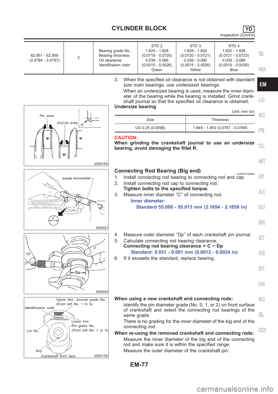
JEM216G
Undersize bearingUnit: mm (in)
Size Thickness
US 0.25 (0.0098) 1.949 - 1.953 (0.0767 - 0.0769)
CAUTION:
When grinding the crankshaft journal to use an undersize
bearing, avoid damaging the fillet R.
AEM027
Connecting Rod Bearing (Big end)NJEM0073S08021. Install connecting rod bearing to connecting rod and cap.
2. Install connecting rod cap to connecting rod.
Tighten bolts to the specified torque.
3. Measure inner diameter “C” of connecting rod.
Inner diameter:
Standard 55.000 - 55.013 mm (2.1654 - 2.1659 in)
AEM034
4. Measure outer diameter “Dp” of each crankshaft pin journal.
5. Calculate connecting rod bearing clearance.
Connecting rod bearing clearance = C − Dp
Standard: 0.031 - 0.061 mm (0.0012 - 0.0024 in)
6. If it exceeds the standard, replace bearing.
JEM215G
When using a new crankshaft and connecting rods:
Identify the pin diameter grade (No. 0, 1, or 2) on front surface
of crankshaft and select the connecting rod bearings of the
same grade.
There is no grading for the inner diameter of the big end of the
connecting rod.
When re-using the removed crankshaft and connecting rods:
Measure the inner diameter of the big end of the connecting
rod and make sure it is within the specified range.
Measure the outer diameter of the crankshaft pin.
GI
MA
LC
EC
FE
CL
MT
AT
AX
SU
BR
ST
RS
BT
HA
SC
EL
IDX
CYLINDER BLOCKYD
Inspection (Cont’d)
EM-77
Page 263 of 3189

EM142
Method B (Using plastigage)
CAUTION:
Do not turn crankshaft or connecting rod while plastigage
is being inserted.
When bearing clearance exceeds the specified limit,
ensure that the proper bearing has been installed. If incor-
rect bearing clearance exists, use a thicker or undersized
main bearing to ensure specified clearance.
SEM502G
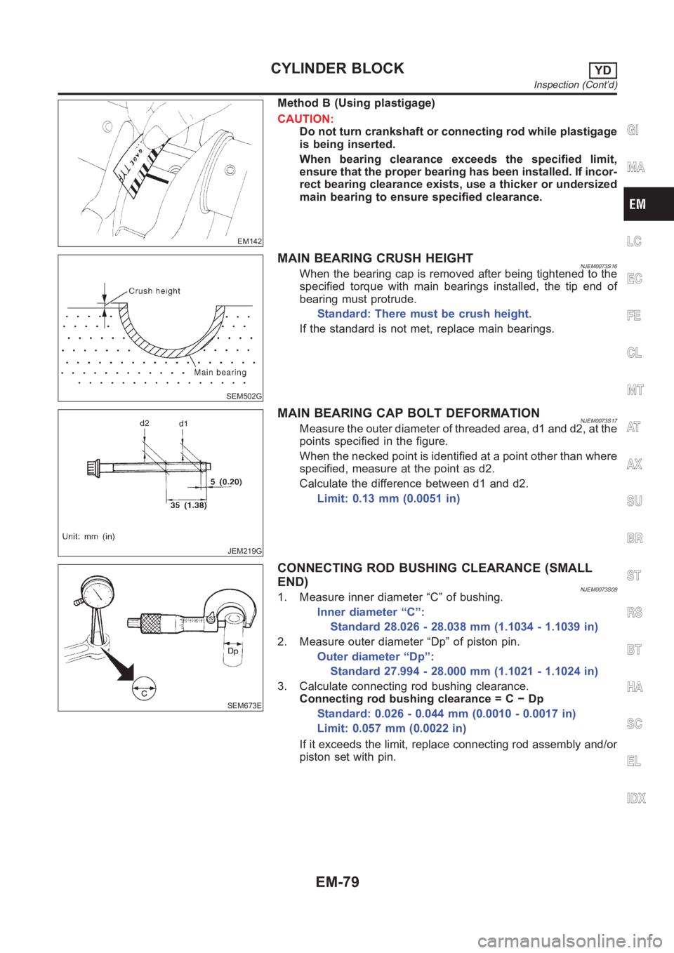
MAIN BEARING CRUSH HEIGHTNJEM0073S16When the bearing cap is removed after being tightened to the
specified torque with main bearings installed, the tip end of
bearing must protrude.
Standard: There must be crush height.
If the standard is not met, replace main bearings.
JEM219G
MAIN BEARING CAP BOLT DEFORMATIONNJEM0073S17Measure the outer diameter of threaded area, d1 and d2, at the
points specified in the figure.
When the necked point is identified at a point other than where
specified, measure at the point as d2.
Calculate the difference between d1 and d2.
Limit: 0.13 mm (0.0051 in)
SEM673E
CONNECTING ROD BUSHING CLEARANCE (SMALL
END)
NJEM0073S091. Measure inner diameter “C” of bushing.
Inner diameter “C”:
Standard 28.026 - 28.038 mm (1.1034 - 1.1039 in)
2. Measure outer diameter “Dp” of piston pin.
Outer diameter “Dp”:
Standard 27.994 - 28.000 mm (1.1021 - 1.1024 in)
3. Calculate connecting rod bushing clearance.
Connecting rod bushing clearance = C − Dp
Standard: 0.026 - 0.044 mm (0.0010 - 0.0017 in)
Limit: 0.057 mm (0.0022 in)
If it exceeds the limit, replace connecting rod assembly and/or
piston set with pin.
GI
MA
LC
EC
FE
CL
MT
AT
AX
SU
BR
ST
RS
BT
HA
SC
EL
IDX
CYLINDER BLOCKYD
Inspection (Cont’d)
EM-79
Page 266 of 3189

JEM213G
c. Be sure to install main bearings in the correct direction.
Make sure those with oil holes or oil grooves are mounted on
the cylinder block side, and those without oil holes or oil
grooves are on the main cap side.
Before installing, apply engine oil on the front (inner) surfaces
of bearings. Do not apply oil to the back surfaces, but thor-
oughly clean them.
Align stopper notches on bearings and install.
Check the oil holes on cylinder block and those on bearings
are aligned.
JEM225G
5. Install crankshaft to cylinder block.
Make sure crankshaft rotates smoothly by hand.
6. Install main bearing caps.
Identify main bearing caps by the punched mark. Install
correctly, matching the journal No. on the bearing cap and the
journal, with the front mark facing forward.
Main bearing caps are commonly processed with the cylinder
block. Therefore, caps and cylinder block should be replaced
as a set.
JEM200G
JEM226G
7. Check the main bearing cap bolts for deformation.
Refer to EM-79, “MAIN BEARING CAP BOLT DEFORMA-
TION”.
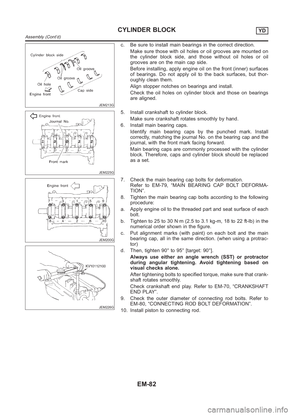
8. Tighten the main bearing cap bolts according to the following
procedure:
a. Apply engine oil to the threaded part and seat surface of each
bolt.
b. Tighten to 25 to 30 N·m (2.5 to 3.1 kg-m, 18 to 22 ft-lb) in the
numerical order shown in the figure.
c. Put alignment marks (with paint) on each bolt and the main
bearing cap, all in the same direction. (when using a protrac-
tor)
d. Then, tighten 90° to 95° [target: 90°].
Always use either an angle wrench (SST) or protractor
during angular tightening. Avoid tightening based on
visual checks alone.
After tightening bolts to specified torque, make sure that crank-
shaft rotates smoothly.
Check crankshaft end play. Refer to EM-70, “CRANKSHAFT
END PLAY”.
9. Check the outer diameter of connecting rod bolts. Refer to
EM-80, “CONNECTING ROD BOLT DEFORMATION”.
10. Install piston to connecting rod.
CYLINDER BLOCKYD
Assembly (Cont’d)
EM-82
Page 268 of 3189

JEM233G
16. Install rear oil seal retainer.
Apply a continuous bead of specified liquid gasket (Refer to
EM-3, “Liquid Gasket Application Procedure”.) on locations
shown in the figure.
JEM234G
17. Install pilot bushing.
Force fit with the drift [approx. 19 mm (0.75 in) dia.].
SEM513G
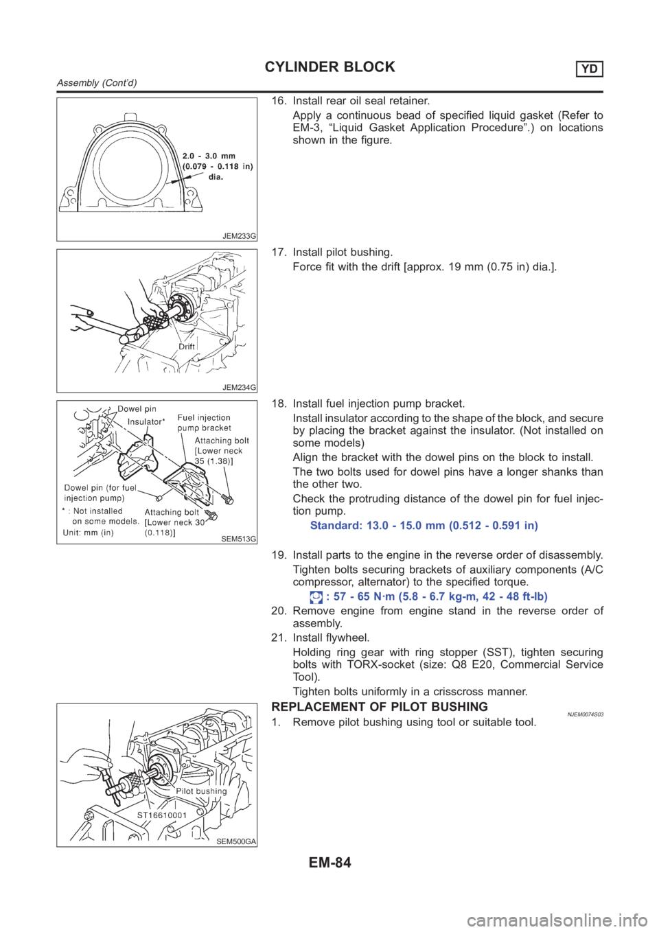
18. Install fuel injection pump bracket.
Install insulator according to the shape of the block, and secure
by placing the bracket against the insulator. (Not installed on
some models)
Align the bracket with the dowel pins on the block to install.
The two bolts used for dowel pins have a longer shanks than
the other two.
Check the protruding distance of the dowel pin for fuel injec-
tion pump.
Standard: 13.0 - 15.0 mm (0.512 - 0.591 in)
19. Install parts to the engine in the reverse order of disassembly.
Tighten bolts securing brackets of auxiliary components (A/C
compressor, alternator) to the specified torque.
: 57 - 65 N·m (5.8 - 6.7 kg-m, 42 - 48 ft-lb)
20. Remove engine from engine stand in the reverse order of
assembly.
21. Install flywheel.
Holding ring gear with ring stopper (SST), tighten securing
bolts with TORX-socket (size: Q8 E20, Commercial Service
Tool).
Tighten bolts uniformly in a crisscross manner.
SEM500GA
REPLACEMENT OF PILOT BUSHINGNJEM0074S031. Remove pilot bushing using tool or suitable tool.
CYLINDER BLOCKYD
Assembly (Cont’d)
EM-84
Page 347 of 3189
![NISSAN ALMERA N16 2003 Electronic Repair Manual PRECAUTIONS
EC-17
[QG (WITH EURO-OBD)]
C
D
E
F
G
H
I
J
K
L
MA
EC
●After performing each TROUBLE DIAGNOSIS, perform
“DTC Confirmation Procedure” or “Overall Function
Check”.
The DTC NISSAN ALMERA N16 2003 Electronic Repair Manual PRECAUTIONS
EC-17
[QG (WITH EURO-OBD)]
C
D
E
F
G
H
I
J
K
L
MA
EC
●After performing each TROUBLE DIAGNOSIS, perform
“DTC Confirmation Procedure” or “Overall Function
Check”.
The DTC](/manual-img/5/57350/w960_57350-346.png)
PRECAUTIONS
EC-17
[QG (WITH EURO-OBD)]
C
D
E
F
G
H
I
J
K
L
MA
EC
●After performing each TROUBLE DIAGNOSIS, perform
“DTC Confirmation Procedure” or “Overall Function
Check”.
The DTC should not be displayed in the “DTC Confirmation
Procedure” if the repair is completed. The “Overall Func-
tion Check” should be a good result if the repair is com-
pleted.
●When measuring ECM signals with a circuit tester, connect
a break-out box (SST) and Y-cable adapter (SST) between
the ECM and ECM harness connector.
●When measuring ECM signals with a circuit tester, never
allow the two tester probes to contact.
Accidental contact of probes will cause a short circuit and
damage the ECM power transistor.
●Do not use ECM ground terminals when measuring input/
output voltage. Doing so may result in damage to the ECM's
transistor. Use a ground other than ECM terminals, such as
the ground.
●Do not operate fuel pump when there is no fuel in lines.
●Tighten fuel hose clamps to the specified torque.
SAT652J
SEF348N
MBIB0046E
Page 364 of 3189
![NISSAN ALMERA N16 2003 Electronic Repair Manual EC-34
[QG (WITH EURO-OBD)]
BASIC SERVICE PROCEDURE
DIAGNOSTIC PROCEDURE
If idle air volume learning cannot be performed successfully, proceed as follows:
1.Check that throttle valve is fully closed.
2 NISSAN ALMERA N16 2003 Electronic Repair Manual EC-34
[QG (WITH EURO-OBD)]
BASIC SERVICE PROCEDURE
DIAGNOSTIC PROCEDURE
If idle air volume learning cannot be performed successfully, proceed as follows:
1.Check that throttle valve is fully closed.
2](/manual-img/5/57350/w960_57350-363.png)
EC-34
[QG (WITH EURO-OBD)]
BASIC SERVICE PROCEDURE
DIAGNOSTIC PROCEDURE
If idle air volume learning cannot be performed successfully, proceed as follows:
1.Check that throttle valve is fully closed.
2.Check PCV valve operation.
3.Check that downstream of throttle valve is free from air leakage.
4.When the above three items check out OK, engine component parts and their installation condi-
tion are questionable. Check and eliminate the cause of the incident.
It is useful to perform EC-105, "
TROUBLE DIAGNOSIS - SPECIFICATION VALUE" .
5.If any of the following conditions occur after the engine has started, eliminate the cause of the
incident and perform “Idle air volume learning” all over again:
–Engine stalls.
–Erroneous idle.
Fuel Pressure CheckEBS00K3E
FUEL PRESSURE RELEASE
Before disconnecting fuel line, release fuel pressure from fuel line to eliminate danger.
NOTE:
Prepare pans or saucers under the disconnected fuel line because the fuel may spill out. The fuel pres-
sure cannot be completely released because N16 models do not have fuel return system.
With CONSULT-II
1. Turn ignition switch “ON”.
2. Perform “FUEL PRESSURE RELEASE” in “WORK SUPPORT”
mode with CONSULT-II.
3. Start engine.
4. After engine stalls, crank it two or three times to release all fuel
pressure.
5. Turn ignition switch “OFF”.
Without CONSULT-II
1. Remove fuel pump fuse located in fuse box.
2. Start engine.
3. After engine stalls, crank it two or three times to release all fuel
pressure.
4. Turn ignition switch “OFF”.
5. Reinstall fuel pump fuse after servicing fuel system.
FUEL PRESSURE CHECK
NOTE:
●When reconnecting fuel line, always use new clamps.
●Make sure that clamp screw does not contact adjacent parts.
●Use a torque driver to tighten clamps.
●Use Pressure Gauge to check fuel pressure.
1. Release fuel pressure to zero. Refer to EC-34, "
FUEL PRESSURE RELEASE" .
SEF214Y
MBIB0262E
Page 449 of 3189
![NISSAN ALMERA N16 2003 Electronic Repair Manual DTC P0011 IVT CONTROL
EC-119
[QG (WITH EURO-OBD)]
C
D
E
F
G
H
I
J
K
L
MA
EC
DTC P0011 IVT CONTROLPFP:23796
DescriptionEBS00K4C
SYSTEM DESCRIPTION
*: This signal is sent to the ECM through CAN communic NISSAN ALMERA N16 2003 Electronic Repair Manual DTC P0011 IVT CONTROL
EC-119
[QG (WITH EURO-OBD)]
C
D
E
F
G
H
I
J
K
L
MA
EC
DTC P0011 IVT CONTROLPFP:23796
DescriptionEBS00K4C
SYSTEM DESCRIPTION
*: This signal is sent to the ECM through CAN communic](/manual-img/5/57350/w960_57350-448.png)
DTC P0011 IVT CONTROL
EC-119
[QG (WITH EURO-OBD)]
C
D
E
F
G
H
I
J
K
L
MA
EC
DTC P0011 IVT CONTROLPFP:23796
DescriptionEBS00K4C
SYSTEM DESCRIPTION
*: This signal is sent to the ECM through CAN communication line.
This mechanism hydraulically controls cam phases continuously with the fixed operating angle of the intake
valve.
The ECM receives signals such as crankshaft position, camshaft position, engine speed, and engine coolant
temperature. Then, the ECM sends ON/OFF pulse duty signals to the intake valve timing control solenoid
valve depending on driving status. This makes it possible to control the shut/open timing of the intake valve to
increase engine torque in low/mid speed range and output in high-speed range.
CONSULT-II Reference Value in Data Monitor ModeEBS00K4D
Specification data are reference values.
Sensor Input Signal to ECM ECM Function Actuator
Crankshaft position sensor (POS)
Engine speed
Intake valve
timing controlIntake valve timing control
solenoid valve Camshaft position sensor (PHASE)
Engine coolant temperature sensor Engine coolant temperature
Vehicle speed signal
*Vehicle speed
MBIB0121E
MONITOR ITEM CONDITION SPECIFICATION
INT/V TIM (B1)
●Engine: After warming up
●Shift lever:
N (A/T models)
Neutral (M/T models)
●Air conditioner switch: OFF
●No-loadIdle−5° - 5°CA
When revving engine up to 2,000 rpm
quicklyApprox. 0° - 30°CA
INT/V SOL (B1)
●Engine: After warming up
●Shift lever:
N (A/T models)
Neutral (M/T models)
●Air conditioner switch: OFF
●No-loadIdle 0% - 2%
When revving engine up to 2,000 rpm
quicklyApprox. 0% - 60%
Page 482 of 3189
![NISSAN ALMERA N16 2003 Electronic Repair Manual EC-152
[QG (WITH EURO-OBD)]
DTC P0132 HO2S1
Specification data are reference values and are measured between each terminal and ground.
CAUTION:
Do not use ECM ground terminals when measuring input/out NISSAN ALMERA N16 2003 Electronic Repair Manual EC-152
[QG (WITH EURO-OBD)]
DTC P0132 HO2S1
Specification data are reference values and are measured between each terminal and ground.
CAUTION:
Do not use ECM ground terminals when measuring input/out](/manual-img/5/57350/w960_57350-481.png)
EC-152
[QG (WITH EURO-OBD)]
DTC P0132 HO2S1
Specification data are reference values and are measured between each terminal and ground.
CAUTION:
Do not use ECM ground terminals when measuring input/output voltage. Doing so may result in dam-
age to the ECM's transistor. Use a ground other than ECM terminals, such as the ground.
Diagnostic ProcedureEBS00K5O
1. RETIGHTEN HEATED OXYGEN SENSOR 1
1. Turn ignition switch “OFF”.
2. Loosen and retighten heated oxygen sensor 1.
>> GO TO 2.
2. CHECK HO2S1 GROUND CIRCUIT FOR OPEN AND SHORT
1. Disconnect heated oxygen sensor 1 harness connector.
2. Disconnect ECM harness connector.
3. Check harness continuity between ECM terminal 74 and HO2S1
terminal 3.
Refer to Wiring Diagram.
4. Also check harness for short to ground and short to power.
OK or NG
OK >> GO TO 3.
NG >> Repair open circuit or short to ground or short to power
in harness or connectors.
TERMI-
NAL
NO.WIRE
COLORITEM CONDITION DATA (DC Voltage)
35 W Heated oxygen sensor 1[Engine is running]
●Warm-up condition
●Engine speed is 2,000 rpm.0 - Approximately 1.0V
(Periodically change)
74 BHeated oxygen sensor
ground[Engine is running]
●Idle speedApproximately 0V
Tightening torque: 40 - 60 N·m (4.1 - 6.2 kg-m, 30 - 44 ft-lb)
MBIB0098E
Continuity should exist.
MBIB0091E