Page 202 of 3189

JEM116G
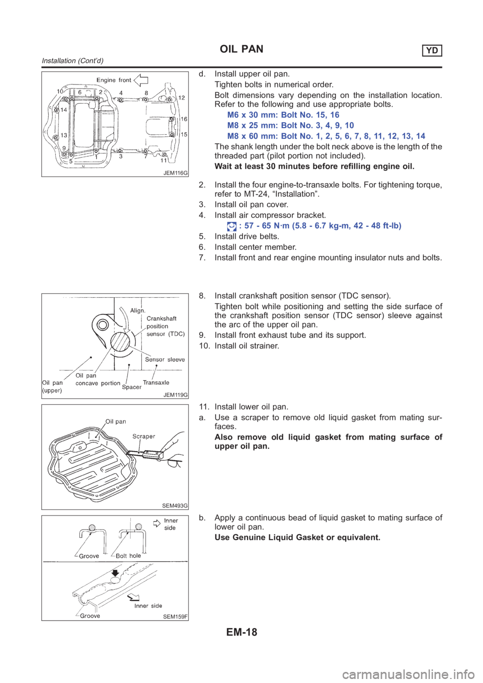
d. Install upper oil pan.
Tighten bolts in numerical order.
Bolt dimensions vary depending on the installation location.
Refer to the following and use appropriate bolts.
M6 x 30 mm: Bolt No. 15, 16
M8x25mm:BoltNo.3,4,9,10
M8x60mm:BoltNo.1,2,5,6,7,8,11,12,13,14
The shank length under the bolt neck above is the length of the
threaded part (pilot portion not included).
Wait at least 30 minutes before refilling engine oil.
2. Install the four engine-to-transaxle bolts. For tightening torque,
refer to MT-24, “Installation”.
3. Install oil pan cover.
4. Install air compressor bracket.
: 57 - 65 N·m (5.8 - 6.7 kg-m, 42 - 48 ft-lb)
5. Install drive belts.
6. Install center member.
7. Install front and rear engine mounting insulator nuts and bolts.
JEM119G
8. Install crankshaft position sensor (TDC sensor).
Tighten bolt while positioning and setting the side surface of
the crankshaft position sensor (TDC sensor) sleeve against
the arc of the upper oil pan.
9. Install front exhaust tube and its support.
10. Install oil strainer.
SEM493G
11. Install lower oil pan.
a. Use a scraper to remove old liquid gasket from mating sur-
faces.
Also remove old liquid gasket from mating surface of
upper oil pan.
SEM159F
b. Apply a continuous bead of liquid gasket to mating surface of
lower oil pan.
Use Genuine Liquid Gasket or equivalent.
OIL PANYD
Installation (Cont’d)
EM-18
Page 218 of 3189

JEM238G
FUEL PIPINGNJEM0109S02RemovalNJEM0109S0201To prevent fuel from flowing out, plug the opening of the hose
with a blind plug after disconnection.
Be careful not to spill fuel in the engine compartment.
InstallationNJEM0109S0202After repairing, bleed air in pipes by shifting priming pump up
and down until the touch is heavy.
For further air bleeding, idle at least 1 minute or more.
SEM489G
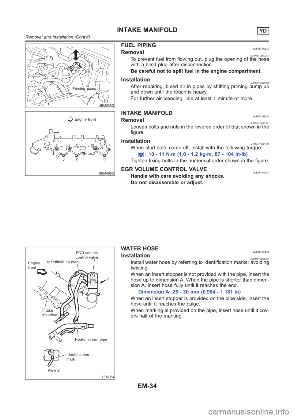
INTAKE MANIFOLDNJEM0109S03RemovalNJEM0109S0301Loosen bolts and nuts in the reverse order of that shown in the
figure.
InstallationNJEM0109S0302When stud bolts come off, install with the following torque:
: 10 - 11 N·m (1.0 - 1.2 kg-m, 87 - 104 in-lb)
Tighten fixing bolts in the numerical order shown in the figure.
EGR VOLUME CONTROL VALVENJEM0109S04Handle with care avoiding any shocks.
Do not disassemble or adjust.
YEM054
WATER HOSENJEM0109S05InstallationNJEM0109S0501Install water hose by referring to identification marks; avoiding
twisting.
When an insert stopper is not provided with the pipe, insert the
hose up to dimension A. When the pipe is shorter than dimen-
sion A, insert hose fully until it reaches the end.
Dimension A: 25 - 30 mm (0.984 - 1.181 in)
When an insert stopper is provided on the pipe side, insert the
hose until it reaches the bulge.
When marking is provided on the pipe, insert hose until it cov-
ers half of the marking.
INTAKE MANIFOLDYD
Removal and Installation (Cont’d)
EM-34
Page 221 of 3189
GUSSETNJEM0101S03InstallationNJEM0101S0301Pushing gussets against the oil pan and the catalytic converter,
temporarily tighten the mounting bolt. And then tighten it to the
specified torque.GI
MA
LC
EC
FE
CL
MT
AT
AX
SU
BR
ST
RS
BT
HA
SC
EL
IDX
CATALYSTYD
Removal and Installation (Cont’d)
EM-37
Page 223 of 3189
InstallationNJEM0102S0202When a stud bolt is pulled out, tighten it to the following torque:
: 18 - 21 N·m (1.8 - 2.2 kg-m, 13 - 15 ft-lb)
Tighten the exhaust manifold mounting nuts in the following
procedure:
a) Tighten the nuts in the order specified in the figure.
b) Re-tighten the nuts 1 to 4.
EXHAUST MANIFOLD GASKETNJEM0102S03InstallationNJEM0102S0301Install the gasket so that the alignment protrusion faces the No. 4
port.
Disassembly and AssemblyNJEM0103
NEM379
TURBOCHARGERNJEM0103S01DisassemblyNJEM0103S0101After applying penetration lubricant (Lucen, etc.) to the mounting
nuts, check for the penetration of the lubricant, and then loosen the
nuts to remove.
GI
MA
LC
EC
FE
CL
MT
AT
AX
SU
BR
ST
RS
BT
HA
SC
EL
IDX
EXHAUST MANIFOLD, TURBOCHARGERYD
Removal and Installation (Cont’d)
EM-39
Page 224 of 3189
CAUTION:
Do not disassemble or adjust the turbocharger body.
AssemblyNJEM0103S0102When a stud bolt is pulled out, tighten it to the following torque:
: 24 - 27 N·m (2.4 - 2.8 kg-m, 18 - 20 ft-lb)
JEM267G
InspectionNJEM0104EXHAUST MANIFOLDNJEM0104S01Check the distortion on the mounting surface in the six directions
using a straightedge and a feeler gauge.
Limit: 0.3 mm (0.012 in)
TURBOCHARGERNJEM0104S02
SEM269G
CAUTION:
When the compressor wheel, turbine wheel, or rotor shaft is
damaged, remove all the fragments and foreign matter left in
the following passages in order to prevent a secondary failure:
Suction side: Between turbocharger and air cleaner
Exhaust side: Between turbocharger and catalytic con-
verter
EXHAUST MANIFOLD, TURBOCHARGERYD
Disassembly and Assembly (Cont’d)
EM-40
Page 227 of 3189
Removal and InstallationNJEM0099
YEM014
PREPARATIVE WORKNJEM0099S01Remove engine cover.
YEM015
ROCKER COVERNJEM0099S02RemovalNJEM0099S0201Loosen holding bolts in the reverse order of that shown in the fig-
ure and remove.
CAUTION:
Do not remove mass damper on top. If damper must be
removed, remove all traces of old locking sealant from threads
of bolts and holes, and apply new locking sealant on the bolts
before tightening.
InstallationNJEM0099S0202Tighten holding bolts in the numerical order shown in the fig-
ure.
Re-tighten to the same torque in the same order as above.
GI
MA
LC
EC
FE
CL
MT
AT
AX
SU
BR
ST
RS
BT
HA
SC
EL
IDX
ROCKER COVERYD
Removal and Installation
EM-43
Page 233 of 3189

CAMSHAFT VISUAL CHECKNJEM0065S02Check camshaft for scratches, seizure and wear.
JEM161G
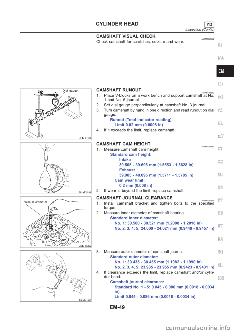
CAMSHAFT RUNOUTNJEM0065S031. Place V-blocks on a work bench and support camshaft at No.
1 and No. 5 journal.
2. Set dial gauge perpendicularly at camshaft No. 3 journal.
3. Turn camshaft by hand in one direction and read runout on dial
gauge.
Runout (Total indicator reading):
Limit 0.02 mm (0.0008 in)
4. If it exceeds the limit, replace camshaft.
SEM549A
CAMSHAFT CAM HEIGHTNJEM0065S041. Measure camshaft cam height.
Standard cam height:
Intake
39.505 - 39.695 mm (1.5553 - 1.5628 in)
Exhaust
39.905 - 40.095 mm (1.5711 - 1.5785 in)
Cam wear limit:
0.2mm(0.008in)
2. If wear is beyond the limit, replace camshaft.
JEM162G
CAMSHAFT JOURNAL CLEARANCENJEM0065S051. Install camshaft bracket and tighten bolts to the specified
torque.
2. Measure inner diameter of camshaft bearing.
Standard inner diameter:
No. 1: 30.500 - 30.521 mm (1.2008 - 1.2016 in)
No. 2, 3, 4, 5: 24.000 - 24.021 mm (0.9449 - 0.9457 in)
SEM012A
3. Measure outer diameter of camshaft journal.
Standard outer diameter:
No. 1: 30.435 - 30.455 mm (1.1982 - 1.1990 in)
No. 2, 3, 4, 5: 23.935 - 23.955 mm (0.9423 - 0.9431 in)
4. If clearance exceeds the limit, replace camshaft and/or cylin-
der head.
Camshaft journal clearance:
Standard No. 1 - 5: 0.045 - 0.086 mm (0.0018 - 0.0034
in)
Limit 0.045 - 0.086 mm (0.0018 - 0.0034 in)
GI
MA
LC
EC
FE
CL
MT
AT
AX
SU
BR
ST
RS
BT
HA
SC
EL
IDX
CYLINDER HEADYD
Inspection (Cont’d)
EM-49
Page 259 of 3189

SEM316A
CRANKSHAFTNJEM0073S071. Check crankshaft main and pin journals for score, wear or
cracks.
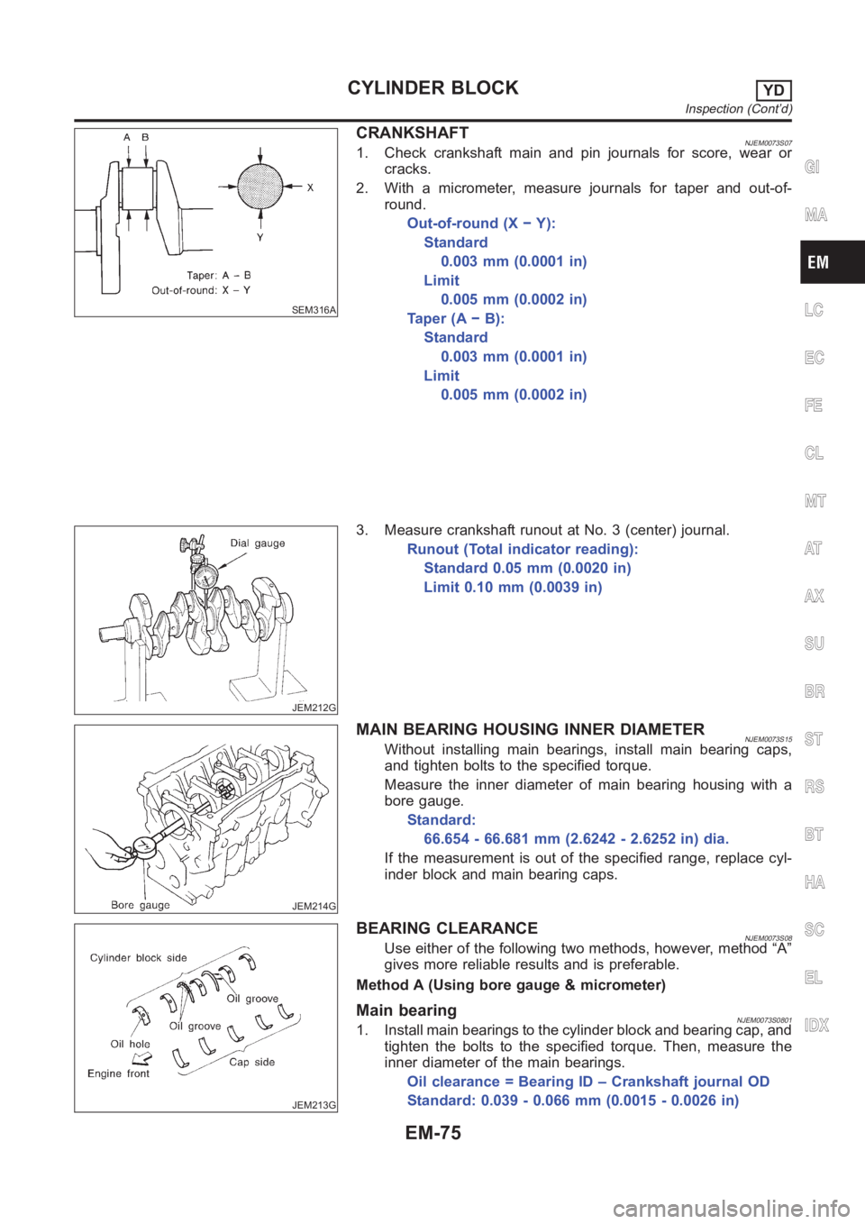
2. With a micrometer, measure journals for taper and out-of-
round.
Out-of-round (X − Y):
Standard
0.003 mm (0.0001 in)
Limit
0.005 mm (0.0002 in)
Ta p e r ( A − B ) :
Standard
0.003 mm (0.0001 in)
Limit
0.005 mm (0.0002 in)
JEM212G
3. Measure crankshaft runout at No. 3 (center) journal.
Runout (Total indicator reading):
Standard 0.05 mm (0.0020 in)
Limit 0.10 mm (0.0039 in)
JEM214G
MAIN BEARING HOUSING INNER DIAMETERNJEM0073S15Without installing main bearings, install main bearing caps,
and tighten bolts to the specified torque.
Measure the inner diameter of main bearing housing with a
bore gauge.
Standard:
66.654 - 66.681 mm (2.6242 - 2.6252 in) dia.
If the measurement is out of the specified range, replace cyl-
inder block and main bearing caps.
JEM213G
BEARING CLEARANCENJEM0073S08Use either of the following two methods, however, method “A”
gives more reliable results and is preferable.
Method A (Using bore gauge & micrometer)
Main bearingNJEM0073S08011. Install main bearings to the cylinder block and bearing cap, and
tighten the bolts to the specified torque. Then, measure the
inner diameter of the main bearings.
Oil clearance = Bearing ID – Crankshaft journal OD
Standard: 0.039 - 0.066 mm (0.0015 - 0.0026 in)
GI
MA
LC
EC
FE
CL
MT
AT
AX
SU
BR
ST
RS
BT
HA
SC
EL
IDX
CYLINDER BLOCKYD
Inspection (Cont’d)
EM-75