Page 193 of 3189
NJEM0053
JEM111G
1. Warm up engine.
2. Turn ignition switch OFF.
3. Using CONSULT-II, make sure no error codes are indicated for
self-diagnosis items. Refer to EC-39, “CONSULT-II Inspection
Procedure”.
Do not disconnect CONSULT-II until the end of this operation;
it will be used to check engine rpm and for error detection at
the end of this operation.
4. Disconnect the negative battery terminal.
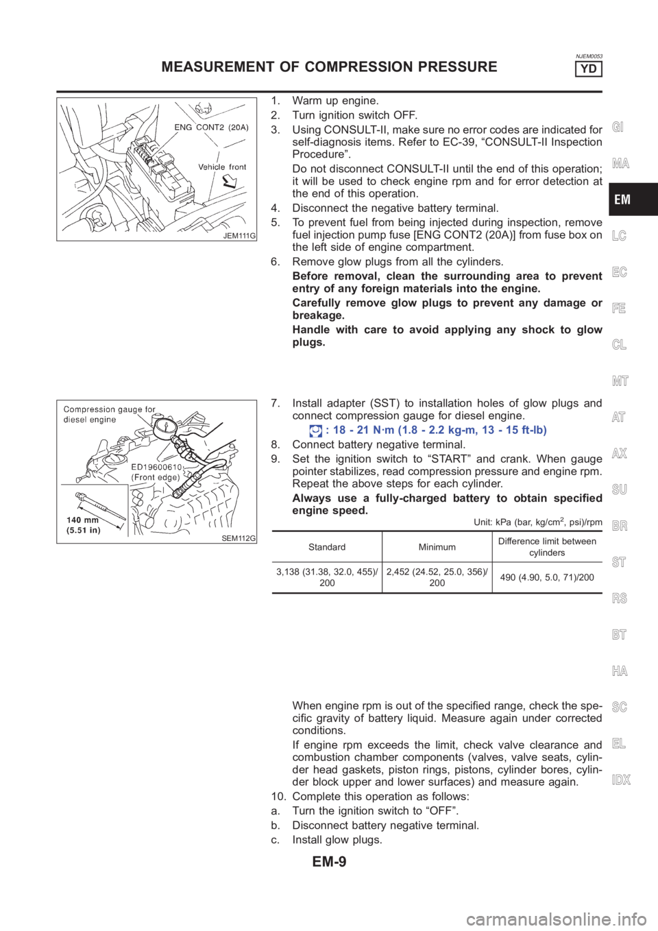
5. To prevent fuel from being injected during inspection, remove
fuel injection pump fuse [ENG CONT2 (20A)] from fuse box on
the left side of engine compartment.
6. Remove glow plugs from all the cylinders.
Before removal, clean the surrounding area to prevent
entry of any foreign materials into the engine.
Carefully remove glow plugs to prevent any damage or
breakage.
Handle with care to avoid applying any shock to glow
plugs.
SEM112G
7. Install adapter (SST) to installation holes of glow plugs and
connect compression gauge for diesel engine.
: 18 - 21 N·m (1.8 - 2.2 kg-m, 13 - 15 ft-lb)
8. Connect battery negative terminal.
9. Set the ignition switch to “START” and crank. When gauge
pointer stabilizes, read compression pressure and engine rpm.
Repeat the above steps for each cylinder.
Always use a fully-charged battery to obtain specified
engine speed.
Unit: kPa (bar, kg/cm2, psi)/rpm
Standard MinimumDifference limit between
cylinders
3,138 (31.38, 32.0, 455)/
2002,452 (24.52, 25.0, 356)/
200490 (4.90, 5.0, 71)/200
When engine rpm is out of the specified range, check the spe-
cific gravity of battery liquid. Measure again under corrected
conditions.
If engine rpm exceeds the limit, check valve clearance and
combustion chamber components (valves, valve seats, cylin-
der head gaskets, piston rings, pistons, cylinder bores, cylin-
der block upper and lower surfaces) and measure again.
10. Complete this operation as follows:
a. Turn the ignition switch to “OFF”.
b. Disconnect battery negative terminal.
c. Install glow plugs.
GI
MA
LC
EC
FE
CL
MT
AT
AX
SU
BR
ST
RS
BT
HA
SC
EL
IDX
MEASUREMENT OF COMPRESSION PRESSUREYD
EM-9
Page 194 of 3189
d. Install fuel injection pump fuse [ENG CONT2 (20A)].
e. Connect battery negative terminal.
f. Using CONSULT-II make sure no error code is indicated for
items of self-diagnosis. Refer to EC-39, “CONSULT-II Inspec-
tion Procedure”.
MEASUREMENT OF COMPRESSION PRESSUREYD
EM-10
Page 204 of 3189
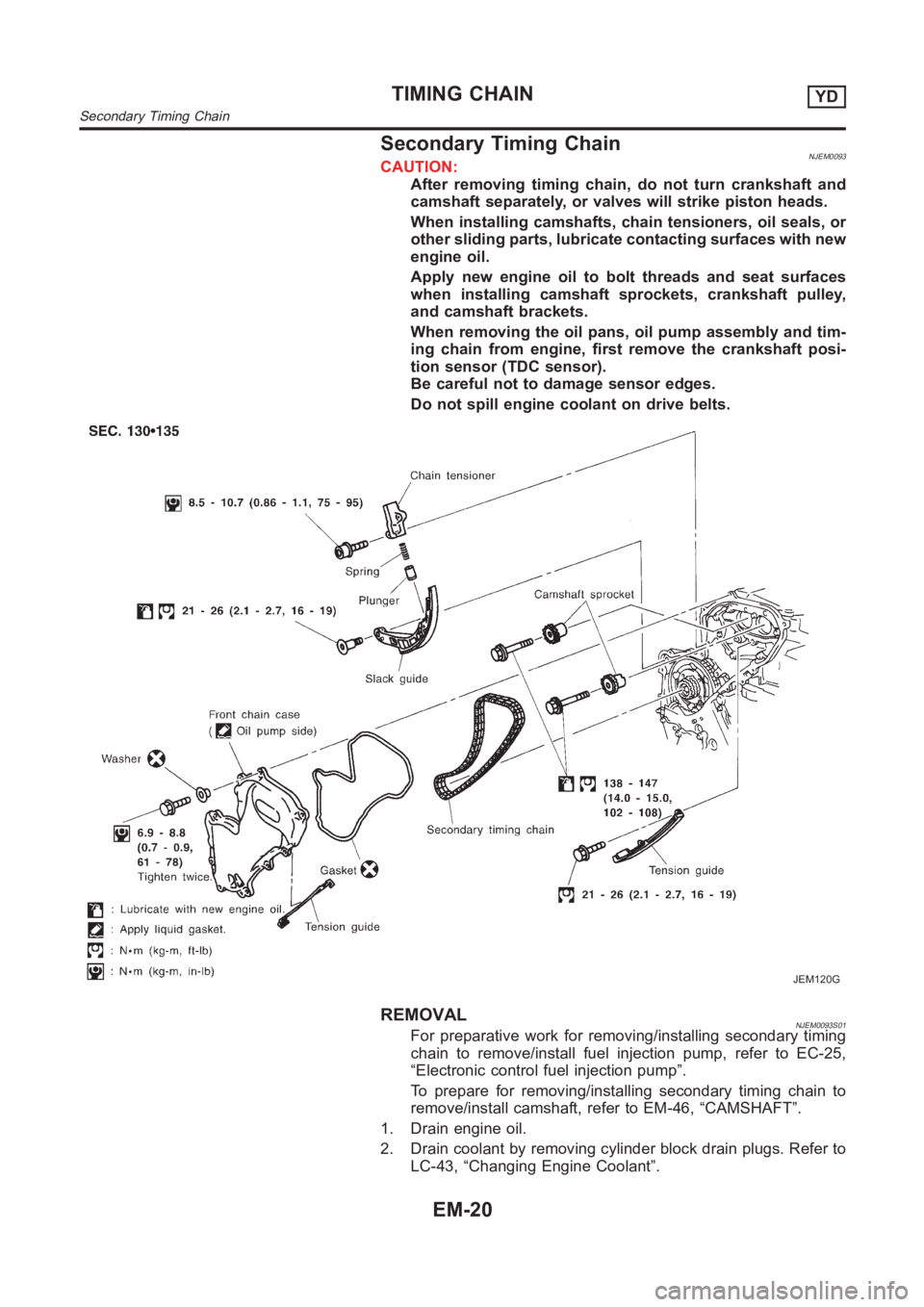
Secondary Timing ChainNJEM0093CAUTION:
After removing timing chain, do not turn crankshaft and
camshaft separately, or valves will strike piston heads.
When installing camshafts, chain tensioners, oil seals, or
other sliding parts, lubricate contacting surfaces with new
engine oil.
Apply new engine oil to bolt threads and seat surfaces
when installing camshaft sprockets, crankshaft pulley,
and camshaft brackets.
When removing the oil pans, oil pump assembly and tim-
ing chain from engine, first remove the crankshaft posi-
tion sensor (TDC sensor).
Be careful not to damage sensor edges.
Do not spill engine coolant on drive belts.
JEM120G
REMOVALNJEM0093S01For preparative work for removing/installing secondary timing
chain to remove/install fuel injection pump, refer to EC-25,
“Electronic control fuel injection pump”.
To prepare for removing/installing secondary timing chain to
remove/install camshaft, refer to EM-46, “CAMSHAFT”.
1. Drain engine oil.
2. Drain coolant by removing cylinder block drain plugs. Refer to
LC-43, “Changing Engine Coolant”.
TIMING CHAINYD
Secondary Timing Chain
EM-20
Page 205 of 3189
JEM121G
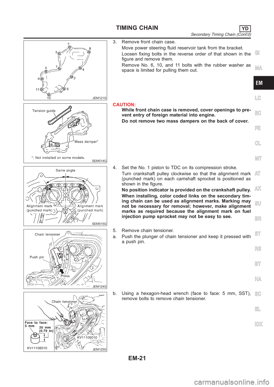
3. Remove front chain case.
Move power steering fluid reservoir tank from the bracket.
Loosen fixing bolts in the reverse order of that shown in the
figure and remove them.
Remove No. 6, 10, and 11 bolts with the rubber washer as
space is limited for pulling them out.
SEM514G
CAUTION:
While front chain case is removed, cover openings to pre-
vent entry of foreign material into engine.
Do not remove two mass dampers on the back of cover.
SEM515G
4. Set the No. 1 piston to TDC on its compression stroke.
Turn crankshaft pulley clockwise so that the alignment mark
(punched mark) on each camshaft sprocket is positioned as
shown in the figure.
No position indicator is provided on the crankshaft pulley.
When installing, color coded links on the secondary tim-
ing chain can be used as alignment marks. Marking may
not be necessary for removal; however, make alignment
marks as required because the alignment mark on fuel
injection pump sprocket may not be easy to see.
JEM124G
5. Remove chain tensioner.
a. Push the plunger of chain tensioner and keep it pressed with
a push pin.
JEM125G
b. Using a hexagon-head wrench (face to face: 5 mm, SST),
remove bolts to remove chain tensioner.
GI
MA
LC
EC
FE
CL
MT
AT
AX
SU
BR
ST
RS
BT
HA
SC
EL
IDX
TIMING CHAINYD
Secondary Timing Chain (Cont’d)
EM-21
Page 211 of 3189
JEM134G
9. Remove chain tensioner.
When removing chain tensioner, push the sleeve of chain ten-
sioner and keep it pressed with a push pin, etc.
10. Remove timing chain slack guide.
JEM135G
11. Hold fuel injection pump sprocket and remove bolt.
a. Insert positioning stopper pin (SST) into the hole 6 mm (0.24
in) in the diameter on the fuel injection pump sprocket.
b. Using a TORX wrench (SST), turn pump shaft little by little to
adjust the position of fuel injection pump sprocket so that the
holes align.
c. Push positioning stopper pin (SST) through pump sprocket to
fuel injection pump body to hold pump sprocket, and remove
bolt.
JEM136G
12. Remove primary timing chain with fuel injection pump sprocket
and crankshaft sprocket.
JEM137G
13. Remove chain guide and tension guides.
14. Remove fuel injection pump.
15. Remove power steering pump.
GI
MA
LC
EC
FE
CL
MT
AT
AX
SU
BR
ST
RS
BT
HA
SC
EL
IDX
TIMING CHAINYD
Primary Timing Chain (Cont’d)
EM-27
Page 213 of 3189
JEM140G
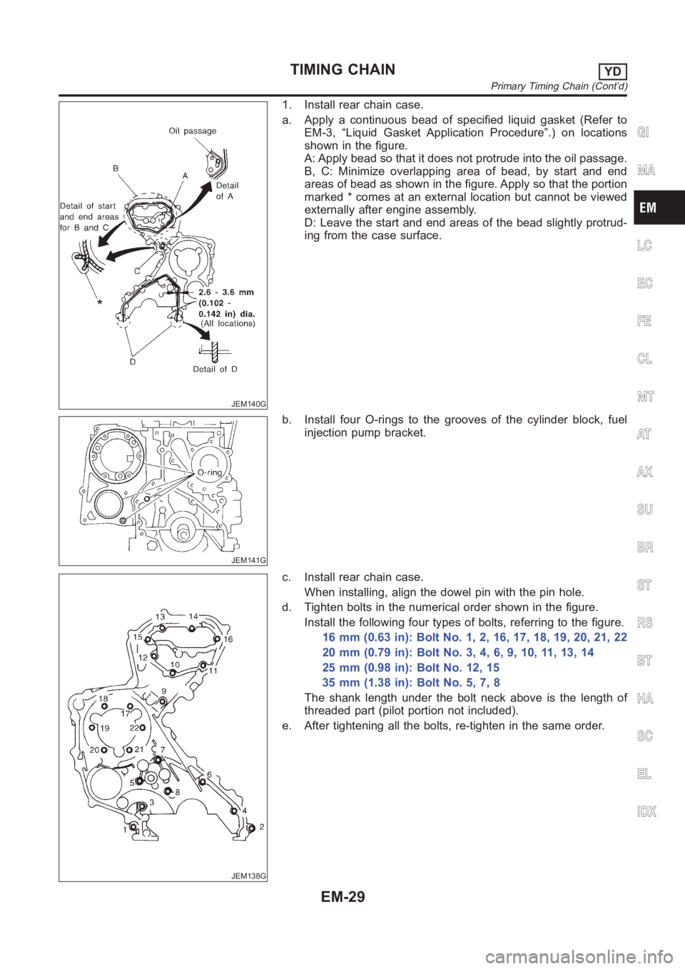
1. Install rear chain case.
a. Apply a continuous bead of specified liquid gasket (Refer to
EM-3, “Liquid Gasket Application Procedure”.) on locations
shown in the figure.
A: Apply bead so that it does not protrude into the oil passage.
B, C: Minimize overlapping area of bead, by start and end
areas of bead as shown in the figure. Apply so that the portion
marked * comes at an external location but cannot be viewed
externally after engine assembly.
D: Leave the start and end areas of the bead slightly protrud-
ing from the case surface.
JEM141G
b. Install four O-rings to the grooves of the cylinder block, fuel
injection pump bracket.
JEM138G
c. Install rear chain case.
When installing, align the dowel pin with the pin hole.
d. Tighten bolts in the numerical order shown in the figure.
Install the following four types of bolts, referring to the figure.
16 mm (0.63 in): Bolt No. 1, 2, 16, 17, 18, 19, 20, 21, 22
20mm(0.79in):BoltNo.3,4,6,9,10,11,13,14
25 mm (0.98 in): Bolt No. 12, 15
35 mm (1.38 in): Bolt No. 5, 7, 8
The shank length under the bolt neck above is the length of
threaded part (pilot portion not included).
e. After tightening all the bolts, re-tighten in the same order.
GI
MA
LC
EC
FE
CL
MT
AT
AX
SU
BR
ST
RS
BT
HA
SC
EL
IDX
TIMING CHAINYD
Primary Timing Chain (Cont’d)
EM-29
Page 214 of 3189
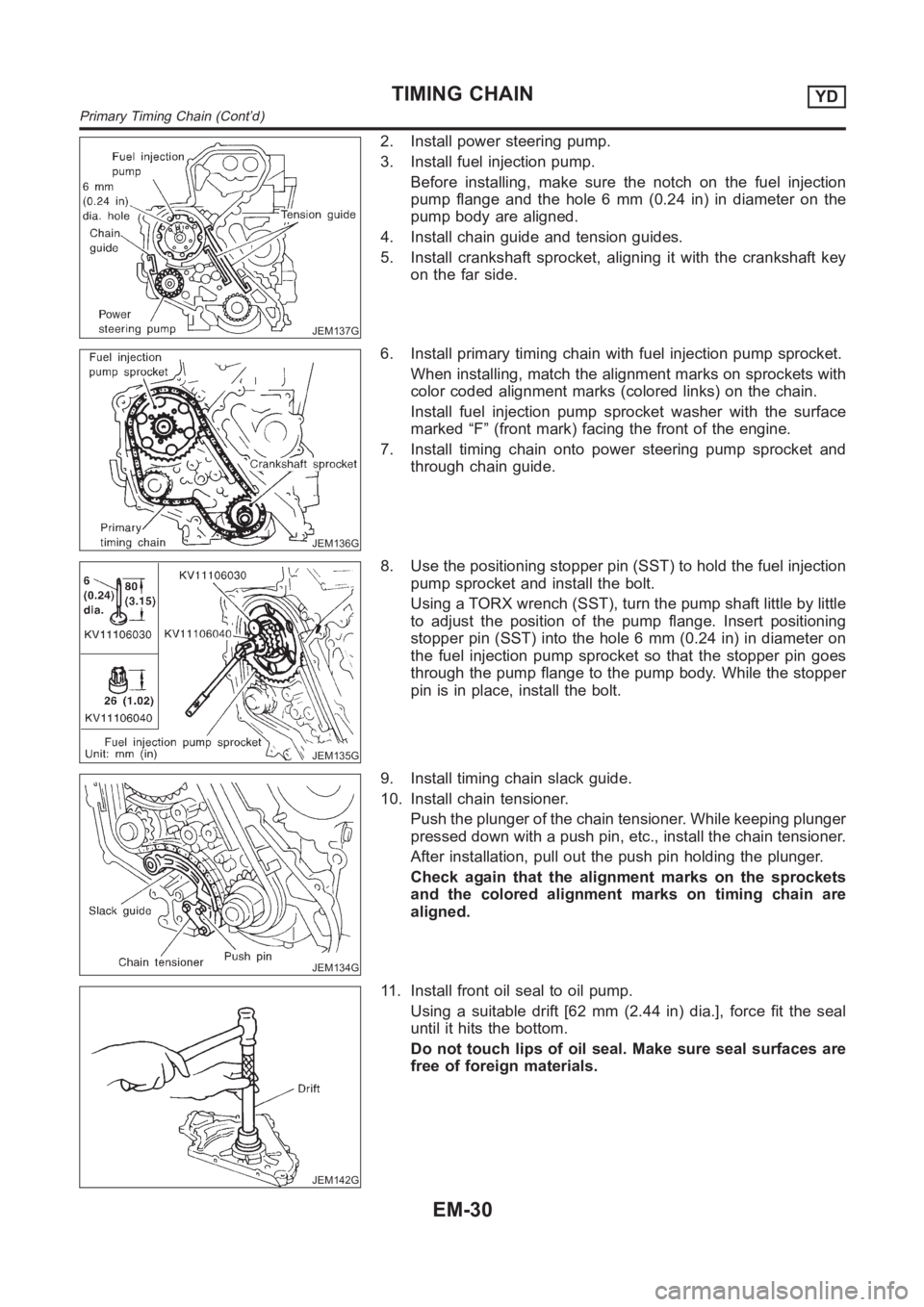
JEM137G
2. Install power steering pump.
3. Install fuel injection pump.
Before installing, make sure the notch on the fuel injection
pump flange and the hole 6 mm (0.24 in) in diameter on the
pump body are aligned.
4. Install chain guide and tension guides.
5. Install crankshaft sprocket, aligning it with the crankshaft key
on the far side.
JEM136G
6. Install primary timing chain with fuel injection pump sprocket.
When installing, match the alignment marks on sprockets with
color coded alignment marks (colored links) on the chain.
Install fuel injection pump sprocket washer with the surface
marked “F” (front mark) facing the front of the engine.
7. Install timing chain onto power steering pump sprocket and
through chain guide.
JEM135G
8. Use the positioning stopper pin (SST) to hold the fuel injection
pump sprocket and install the bolt.
Using a TORX wrench (SST), turn the pump shaft little by little
to adjust the position of the pump flange. Insert positioning
stopper pin (SST) into the hole 6 mm (0.24 in) in diameter on
the fuel injection pump sprocket so that the stopper pin goes
through the pump flange to the pump body. While the stopper
pin is in place, install the bolt.
JEM134G
9. Install timing chain slack guide.
10. Install chain tensioner.
Push the plunger of the chain tensioner. While keeping plunger
pressed down with a push pin, etc., install the chain tensioner.
After installation, pull out the push pin holding the plunger.
Check again that the alignment marks on the sprockets
and the colored alignment marks on timing chain are
aligned.
JEM142G
11. Install front oil seal to oil pump.
Using a suitable drift [62 mm (2.44 in) dia.], force fit the seal
until it hits the bottom.
Do not touch lips of oil seal. Make sure seal surfaces are
free of foreign materials.
TIMING CHAINYD
Primary Timing Chain (Cont’d)
EM-30
Page 217 of 3189
Removal and InstallationNJEM0109
YEM053
SEM565G
PREPARATIVE WORKNJEM0109S011. Drain engine coolant. Refer to LC-43, “Changing engine cool-
ant”.
2. Remove engine cover. Refer to the figure at left.
3. Remove injection tube.
4. Remove blow-by hose (on rocker cover side).
5. Remove or relocate fuel pipes.
6. Remove or relocate wires/harnesses and tubes/pipes.
GI
MA
LC
EC
FE
CL
MT
AT
AX
SU
BR
ST
RS
BT
HA
SC
EL
IDX
INTAKE MANIFOLDYD
Removal and Installation
EM-33