2003 NISSAN ALMERA N16 fuel
[x] Cancel search: fuelPage 218 of 3189
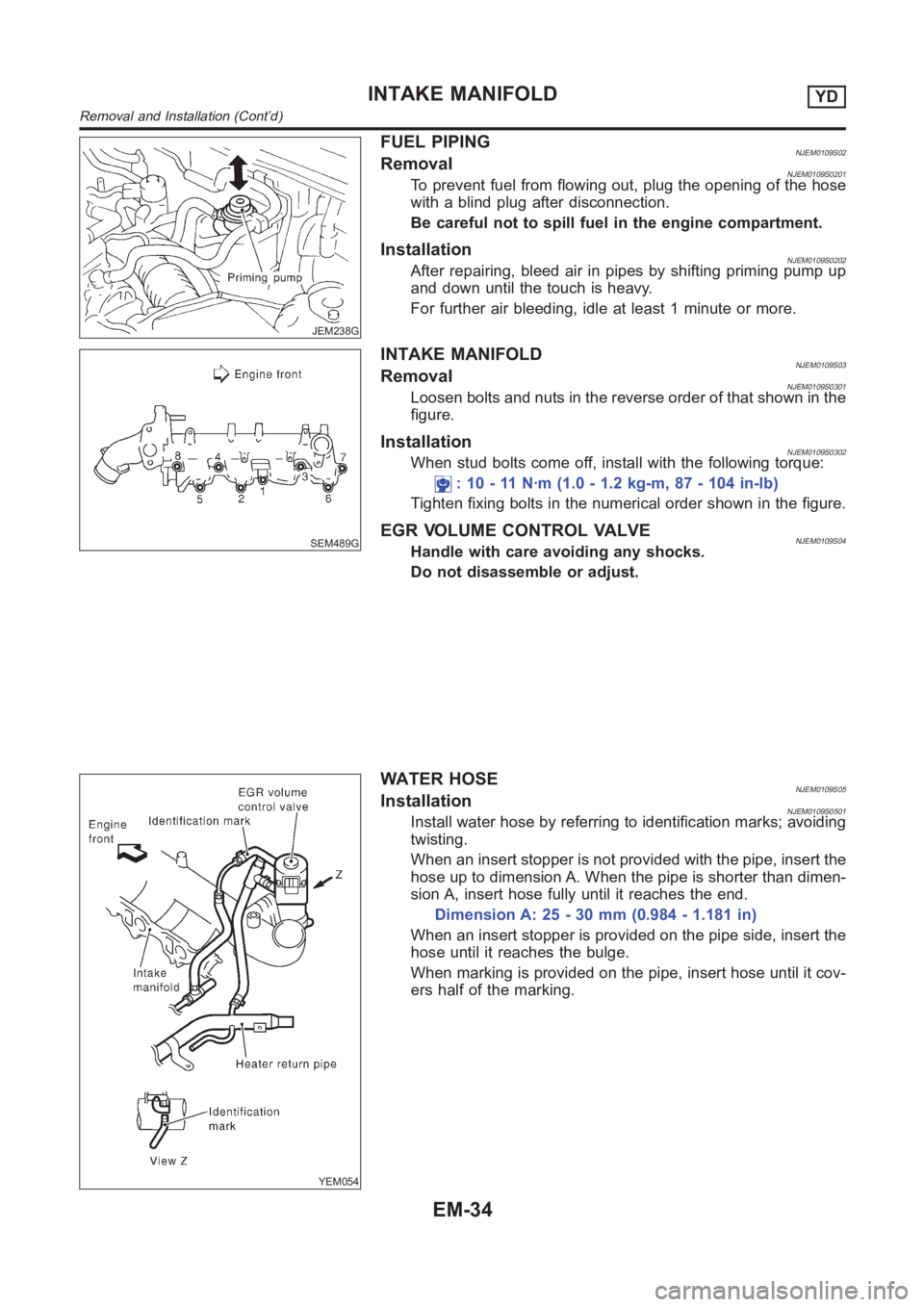
JEM238G
FUEL PIPINGNJEM0109S02RemovalNJEM0109S0201To prevent fuel from flowing out, plug the opening of the hose
with a blind plug after disconnection.
Be careful not to spill fuel in the engine compartment.
InstallationNJEM0109S0202After repairing, bleed air in pipes by shifting priming pump up
and down until the touch is heavy.
For further air bleeding, idle at least 1 minute or more.
SEM489G
INTAKE MANIFOLDNJEM0109S03RemovalNJEM0109S0301Loosen bolts and nuts in the reverse order of that shown in the
figure.
InstallationNJEM0109S0302When stud bolts come off, install with the following torque:
: 10 - 11 N·m (1.0 - 1.2 kg-m, 87 - 104 in-lb)
Tighten fixing bolts in the numerical order shown in the figure.
EGR VOLUME CONTROL VALVENJEM0109S04Handle with care avoiding any shocks.
Do not disassemble or adjust.
YEM054
WATER HOSENJEM0109S05InstallationNJEM0109S0501Install water hose by referring to identification marks; avoiding
twisting.
When an insert stopper is not provided with the pipe, insert the
hose up to dimension A. When the pipe is shorter than dimen-
sion A, insert hose fully until it reaches the end.
Dimension A: 25 - 30 mm (0.984 - 1.181 in)
When an insert stopper is provided on the pipe side, insert the
hose until it reaches the bulge.
When marking is provided on the pipe, insert hose until it cov-
ers half of the marking.
INTAKE MANIFOLDYD
Removal and Installation (Cont’d)
EM-34
Page 247 of 3189
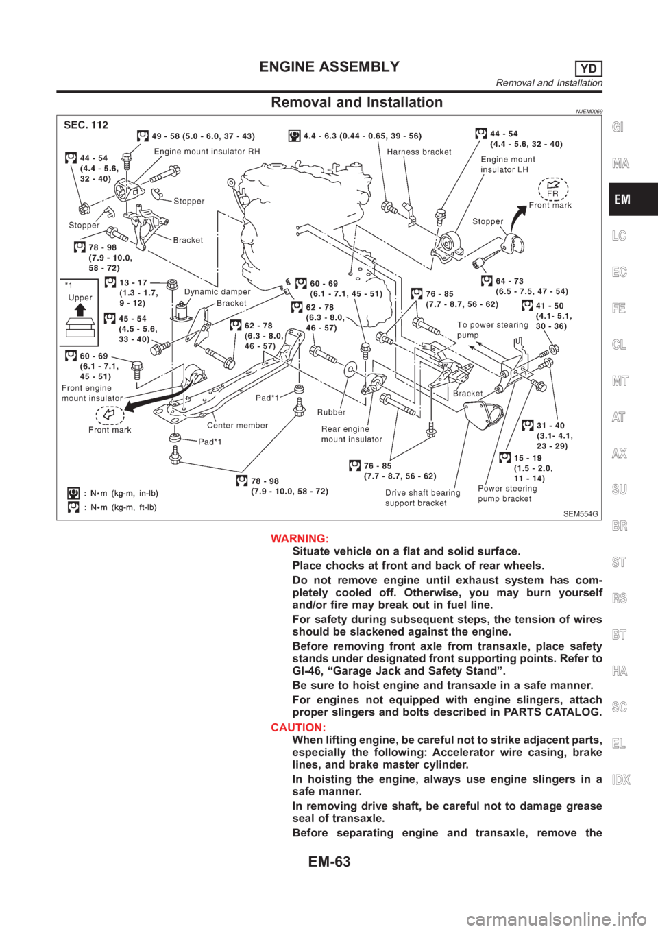
Removal and InstallationNJEM0069
SEM554G
WARNING:
Situate vehicle on a flat and solid surface.
Place chocks at front and back of rear wheels.
Do not remove engine until exhaust system has com-
pletely cooled off. Otherwise, you may burn yourself
and/or fire may break out in fuel line.
For safety during subsequent steps, the tension of wires
should be slackened against the engine.
Before removing front axle from transaxle, place safety
stands under designated front supporting points. Refer to
GI-46, “Garage Jack and Safety Stand”.
Be sure to hoist engine and transaxle in a safe manner.
For engines not equipped with engine slingers, attach
proper slingers and bolts described in PARTS CATALOG.
CAUTION:
When lifting engine, be careful not to strike adjacent parts,
especially the following: Accelerator wire casing, brake
lines, and brake master cylinder.
In hoisting the engine, always use engine slingers in a
safe manner.
In removing drive shaft, be careful not to damage grease
seal of transaxle.
Before separating engine and transaxle, remove the
GI
MA
LC
EC
FE
CL
MT
AT
AX
SU
BR
ST
RS
BT
HA
SC
EL
IDX
ENGINE ASSEMBLYYD
Removal and Installation
EM-63
Page 248 of 3189

crankshaft position sensor (TDC sensor) from the assem-
bly.
Always pay extra attention not to damage edge of crank-
shaft position sensor (TDC sensor) or ring gear teeth.
REMOVALNJEM0069S011. Remove engine undercover, and hood for hoisting.
2. Drain coolant from both cylinder block and radiator. Refer to
LC-43, “Changing Engine Coolant”.
3. Remove the following parts:
Battery
RH and LH front wheels
RH and LH splash covers (combined with undercover)
Auxiliary belts
Alternator
Alternator brackets
Radiator and cooling fan
Engine cover
Air ducts and air cleaner case
LH side of engine room:
4. Disconnect all harnesses and grounds that are connected to
components on vehicle.
5. Disconnect vacuum hose on vacuum pump side.
6. Disconnect fuel feed and fuel return hoses on engine side.
Immediately put blind plugs into the openings to prevent
fuel from flowing out.
7. Disconnect heater hose. Plug opening of hose to prevent cool-
ant from flowing out.
RH side of engine room:
8. Remove air conditioner compressor from brackets and move
it toward vehicle side. Secure compressor on vehicle side with
rope.
Vehicle underside:
9. Remove exhaust front tube.
10. Disconnect two hoses from power steering pump and plug to
stop fluid.
11. Remove M/T control rod and support rod.
12. Remove ABS wheel sensor, and temporarily hang brake cali-
per with rope on vehicle side.
13. Remove RH and LH drive shafts.
YEM024
14. Install engine slingers to cylinder head.
: 30 - 37 N·m (3.0 - 3.8 kg-m, 22 - 27 ft-lb)
Use engine slingers and securing bolts of the specified
service parts.
15. Lift up vehicle to appropriate level where work can be per-
formed efficiently. Using two transmission jacks, securely sup-
port engine oil pan and bottom surface of transaxle.
ENGINE ASSEMBLYYD
Removal and Installation (Cont’d)
EM-64
Page 252 of 3189
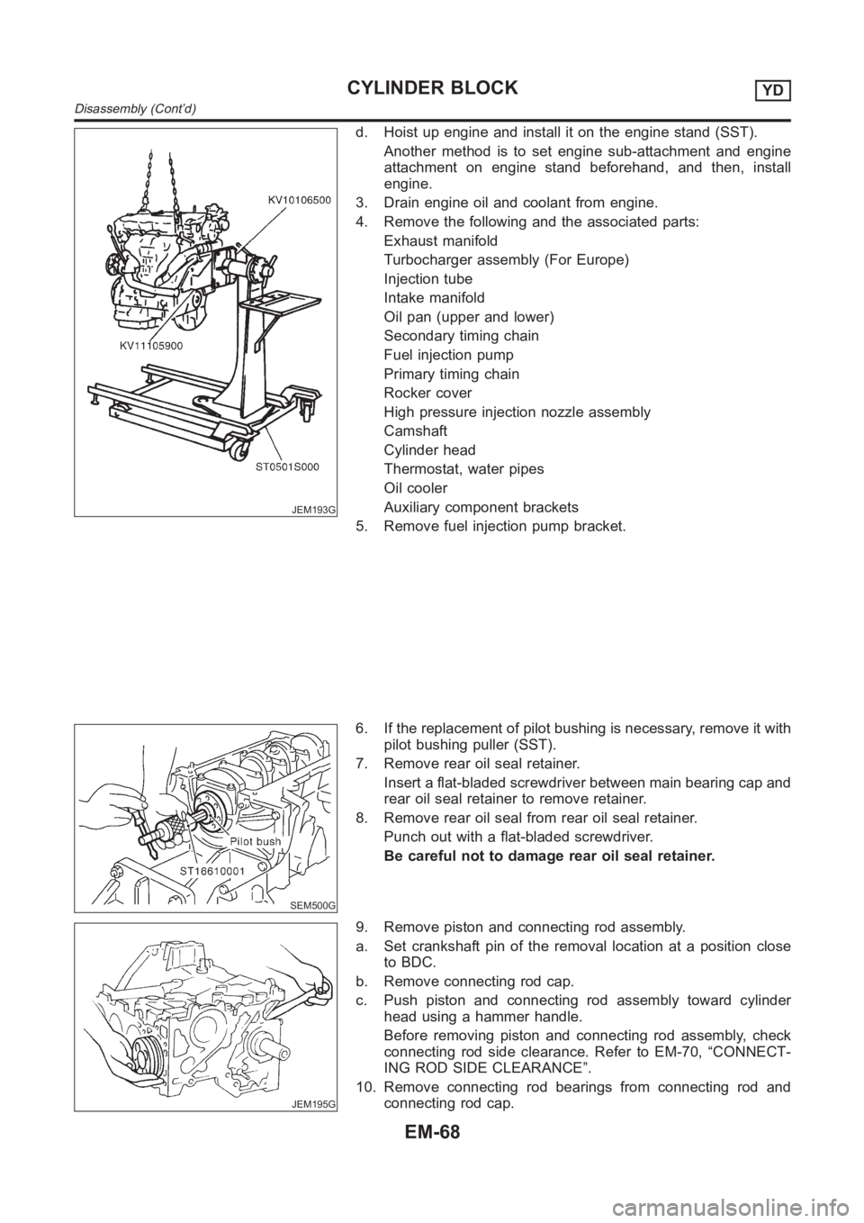
JEM193G
d. Hoist up engine and install it on the engine stand (SST).
Another method is to set engine sub-attachment and engine
attachment on engine stand beforehand, and then, install
engine.
3. Drain engine oil and coolant from engine.
4. Remove the following and the associated parts:
Exhaust manifold
Turbocharger assembly (For Europe)
Injection tube
Intake manifold
Oil pan (upper and lower)
Secondary timing chain
Fuel injection pump
Primary timing chain
Rocker cover
High pressure injection nozzle assembly
Camshaft
Cylinder head
Thermostat, water pipes
Oil cooler
Auxiliary component brackets
5. Remove fuel injection pump bracket.
SEM500G
6. If the replacement of pilot bushing is necessary, remove it with
pilot bushing puller (SST).
7. Remove rear oil seal retainer.
Insert a flat-bladed screwdriver between main bearing cap and
rear oil seal retainer to remove retainer.
8. Remove rear oil seal from rear oil seal retainer.
Punch out with a flat-bladed screwdriver.
Be careful not to damage rear oil seal retainer.
JEM195G
9. Remove piston and connecting rod assembly.
a. Set crankshaft pin of the removal location at a position close
to BDC.
b. Remove connecting rod cap.
c. Push piston and connecting rod assembly toward cylinder
head using a hammer handle.
Before removing piston and connecting rod assembly, check
connecting rod side clearance. Refer to EM-70, “CONNECT-
ING ROD SIDE CLEARANCE”.
10. Remove connecting rod bearings from connecting rod and
connecting rod cap.
CYLINDER BLOCKYD
Disassembly (Cont’d)
EM-68
Page 268 of 3189
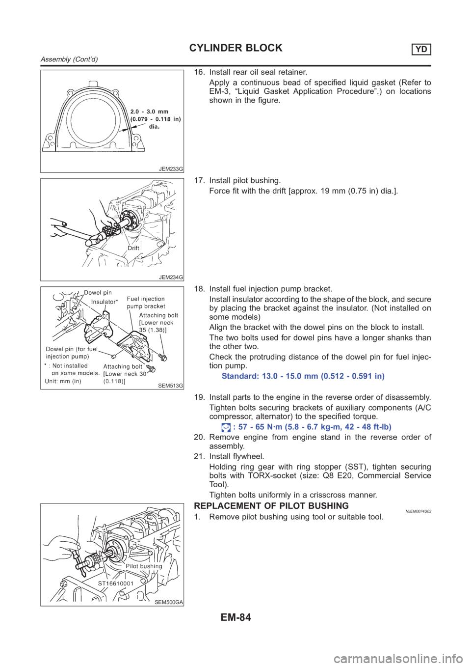
JEM233G
16. Install rear oil seal retainer.
Apply a continuous bead of specified liquid gasket (Refer to
EM-3, “Liquid Gasket Application Procedure”.) on locations
shown in the figure.
JEM234G
17. Install pilot bushing.
Force fit with the drift [approx. 19 mm (0.75 in) dia.].
SEM513G
18. Install fuel injection pump bracket.
Install insulator according to the shape of the block, and secure
by placing the bracket against the insulator. (Not installed on
some models)
Align the bracket with the dowel pins on the block to install.
The two bolts used for dowel pins have a longer shanks than
the other two.
Check the protruding distance of the dowel pin for fuel injec-
tion pump.
Standard: 13.0 - 15.0 mm (0.512 - 0.591 in)
19. Install parts to the engine in the reverse order of disassembly.
Tighten bolts securing brackets of auxiliary components (A/C
compressor, alternator) to the specified torque.
: 57 - 65 N·m (5.8 - 6.7 kg-m, 42 - 48 ft-lb)
20. Remove engine from engine stand in the reverse order of
assembly.
21. Install flywheel.
Holding ring gear with ring stopper (SST), tighten securing
bolts with TORX-socket (size: Q8 E20, Commercial Service
Tool).
Tighten bolts uniformly in a crisscross manner.
SEM500GA
REPLACEMENT OF PILOT BUSHINGNJEM0074S031. Remove pilot bushing using tool or suitable tool.
CYLINDER BLOCKYD
Assembly (Cont’d)
EM-84
Page 331 of 3189
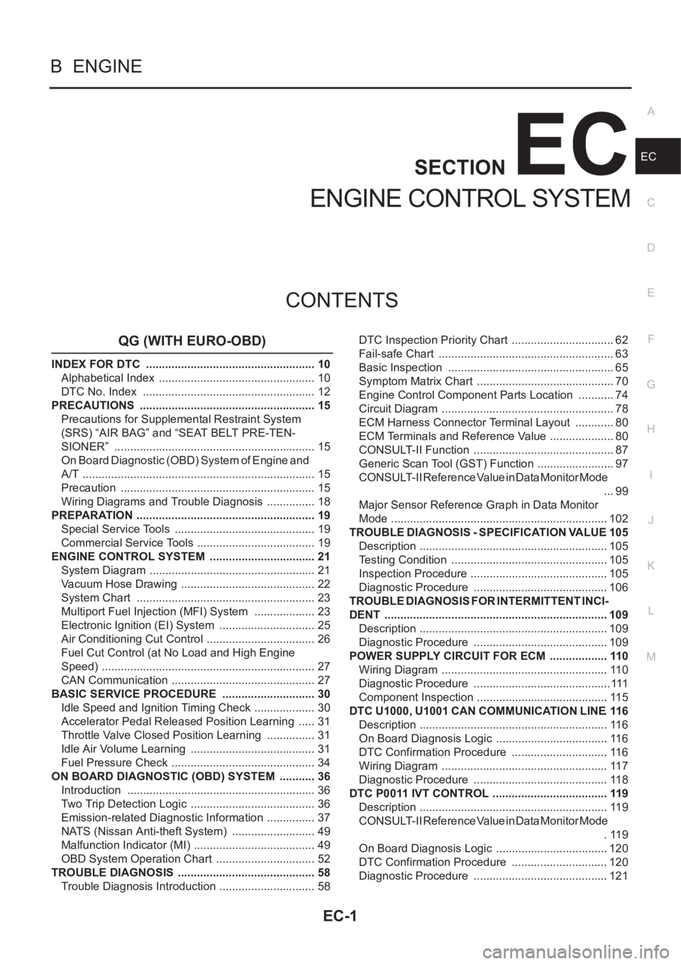
EC-1
ENGINE CONTROL SYSTEM
B ENGINE
CONTENTS
C
D
E
F
G
H
I
J
K
L
M
SECTION
A
EC
ENGINE CONTROL SYSTEM
QG (WITH EURO-OBD)
INDEX FOR DTC ...................................................... 10
Alphabetical Index .................................................. 10
DTC No. Index ....................................................... 12
PRECAUTIONS ........................................................ 15
Precautions for Supplemental Restraint System
(SRS) “AIR BAG” and “SEAT BELT PRE-TEN-
SIONER” ................................................................ 15
On Board Diagnostic (OBD) System of Engine and
A/T .......................................................................... 15
Precaution .............................................................. 15
Wiring Diagrams and Trouble Diagnosis ................ 18
PREPARATION ......................................................... 19
Special Service Tools ............................................. 19
Commercial Service Tools ...................................... 19
ENGINE CONTROL SYSTEM .................................. 21
System Diagram ..................................................... 21
Vacuum Hose Drawing ........................................... 22
System Chart ......................................................... 23
Multiport Fuel Injection (MFI) System .................... 23
Electronic Ignition (EI) System ............................... 25
Air Conditioning Cut Control ................................... 26
Fuel Cut Control (at No Load and High Engine
Speed) .................................................................... 27
CAN Communication .............................................. 27
BASIC SERVICE PROCEDURE .............................. 30
Idle Speed and Ignition Timing Check .................... 30
Accelerator Pedal Released Position Learning ...... 31
Throttle Valve Closed Position Learning ................ 31
Idle Air Volume Learning ........................................ 31
Fuel Pressure Check .............................................. 34
ON BOARD DIAGNOSTIC (OBD) SYSTEM ............ 36
Introduction ............................................................ 36
Two Trip Detection Logic ........................................ 36
Emission-related Diagnostic Information ................ 37
NATS (Nissan Anti-theft System) ........................... 49
Malfunction Indicator (MI) ....................................... 49
OBD System Operation Chart ................................ 52
TROUBLE DIAGNOSIS ............................................ 58
Trouble Diagnosis Introduction ............................... 58DTC Inspection Priority Chart ................................. 62
Fail-safe Chart ........................................................ 63
Basic Inspection ..................................................... 65
Symptom Matrix Chart ............................................ 70
Engine Control Component Parts Location ............ 74
Circuit Diagram ....................................................... 78
ECM Harness Connector Terminal Layout ............. 80
ECM Terminals and Reference Value ..................
... 80
CONSULT-II Function ............................................. 87
Generic Scan Tool (GST) Function ......................... 97
CONSULT-II Reference Value in Data Monitor Mode
... 99
Major Sensor Reference Graph in Data Monitor
Mode .....................................................................102
TROUBLE DIAGNOSIS - SPECIFICATION VALUE .105
Description ............................................................105
Testing Condition ..................................................105
Inspection Procedure ............................................105
Diagnostic Procedure ...........................................106
TROUBLE DIAGNOSIS FOR INTERMITTENT INCI-
DENT .......................................................................109
Description ............................................................109
Diagnostic Procedure ...........................................109
POWER SUPPLY CIRCUIT FOR ECM ...................110
Wiring Diagram .....................................................110
Diagnostic Procedure ............................................111
Component Inspection ..........................................115
DTC U1000, U1001 CAN COMMUNICATION LINE .116
Description ............................................................116
On Board Diagnosis Logic ....................................116
DTC Confirmation Procedure ...............................116
Wiring Diagram .....................................................117
Diagnostic Procedure ...........................................118
DTC P0011 IVT CONTROL .....................................119
Description ............................................................119
CONSULT-II Reference Value in Data Monitor Mode
.119
On Board Diagnosis Logic ....................................120
DTC Confirmation Procedure ...............................120
Diagnostic Procedure ...........................................121
Page 332 of 3189
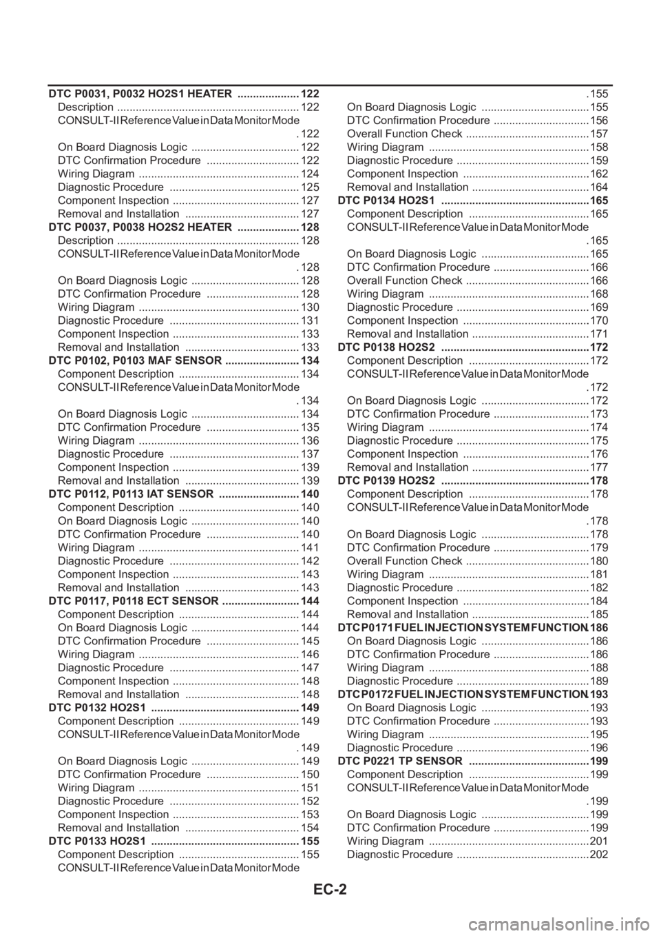
EC-2
DTC P0031, P0032 HO2S1 HEATER .....................122
Description ............................................................122
CONSULT-II Reference Value in Data Monitor Mode
.122
On Board Diagnosis Logic ....................................122
DTC Confirmation Procedure ...............................122
Wiring Diagram .....................................................124
Diagnostic Procedure ...........................................125
Component Inspection ..........................................127
Removal and Installation ......................................127
DTC P0037, P0038 HO2S2 HEATER .....................128
Description ............................................................128
CONSULT-II Reference Value in Data Monitor Mode
.128
On Board Diagnosis Logic ....................................128
DTC Confirmation Procedure ...............................128
Wiring Diagram .....................................................130
Diagnostic Procedure ...........................................131
Component Inspection ..........................................133
Removal and Installation ......................................133
DTC P0102, P0103 MAF SENSOR .........................134
Component Description ........................................134
CONSULT-II Reference Value in Data Monitor Mode
.134
On Board Diagnosis Logic ....................................134
DTC Confirmation Procedure ...............................135
Wiring Diagram .....................................................136
Diagnostic Procedure ...........................................137
Component Inspection ..........................................139
Removal and Installation ......................................139
DTC P0112, P0113 IAT SENSOR ...........................140
Component Description ........................................140
On Board Diagnosis Logic ....................................140
DTC Confirmation Procedure ...............................140
Wiring Diagram .....................................................141
Diagnostic Procedure ...........................................142
Component Inspection ..........................................143
Removal and Installation ......................................143
DTC P0117, P0118 ECT SENSOR ..........................144
Component Description ........................................144
On Board Diagnosis Logic ....................................144
DTC Confirmation Procedure ...............................145
Wiring Diagram .....................................................146
Diagnostic Procedure ...........................................147
Component Inspection ..........................................148
Removal and Installation ......................................148
DTC P0132 HO2S1 .................................................149
Component Description ........................................149
CONSULT-II Reference Value in Data Monitor Mode
.149
On Board Diagnosis Logic ...................................
.149
DTC Confirmation Procedure ...............................150
Wiring Diagram .....................................................151
Diagnostic Procedure ...........................................152
Component Inspection ..........................................153
Removal and Installation ......................................154
DTC P0133 HO2S1 .................................................155
Component Description ........................................155
CONSULT-II Reference Value in Data Monitor Mode .155
On Board Diagnosis Logic ....................................155
DTC Confirmation Procedure ................................156
Overall Function Check .........................................157
Wiring Diagram .....................................................158
Diagnostic Procedure ............................................159
Component Inspection ..........................................162
Removal and Installation .......................................164
DTC P0134 HO2S1 ................................................ .165
Component Description ........................................165
CONSULT-II Reference Value in Data Monitor Mode
.165
On Board Diagnosis Logic ....................................165
DTC Confirmation Procedure ................................166
Overall Function Check .........................................166
Wiring Diagram .....................................................168
Diagnostic Procedure ............................................169
Component Inspection ..........................................170
Removal and Installation .......................................171
DTC P0138 HO2S2 ................................................ .172
Component Description ........................................172
CONSULT-II Reference Value in Data Monitor Mode
.172
On Board Diagnosis Logic ....................................172
DTC Confirmation Procedure ................................173
Wiring Diagram .....................................................174
Diagnostic Procedure ............................................175
Component Inspection ..........................................176
Removal and Installation .......................................177
DTC P0139 HO2S2 ................................................ .178
Component Description ........................................178
CONSULT-II Reference Value in Data Monitor Mode
.178
On Board Diagnosis Logic ....................................178
DTC Confirmation Procedure ................................179
Overall Function Check .........................................180
Wiring Diagram .....................................................181
Diagnostic Procedure ............................................182
Component Inspection ..........................................184
Removal and Installation ......................................
.185
DTC P0171 FUEL INJECTION SYSTEM FUNCTION .186
On Board Diagnosis Logic ....................................186
DTC Confirmation Procedure ................................186
Wiring Diagram .....................................................188
Diagnostic Procedure ............................................189
DTC P0172 FUEL INJECTION SYSTEM FUNCTION .193
On Board Diagnosis Logic ....................................193
DTC Confirmation Procedure ................................193
Wiring Diagram .....................................................195
Diagnostic Procedure ............................................196
DTC P0221 TP SENSOR ........................................199
Component Description ........................................199
CONSULT-II Reference Value in Data Monitor Mode
.199
On Board Diagnosis Logic ....................................199
DTC Confirmation Procedure ................................199
Wiring Diagram .....................................................201
Diagnostic Procedure ............................................202
Page 335 of 3189
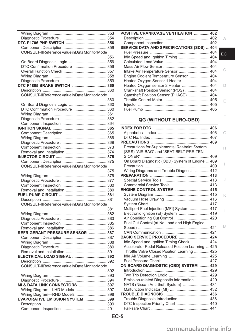
EC-5
C
D
E
F
G
H
I
J
K
L
M
ECA Wiring Diagram .................................................... 353
Diagnostic Procedure ........................................... 354
DTC P1706 PNP SWITCH ...................................... 356
Component Description ........................................ 356
CONSULT-II Reference Value in Data Monitor Mode
. 356
On Board Diagnosis Logic ................................... 356
DTC Confirmation Procedure ............................... 356
Overall Function Check ........................................ 357
Wiring Diagram .................................................... 358
Diagnostic Procedure ........................................... 359
DTC P1805 BRAKE SWITCH ................................ 360
Description ........................................................... 360
CONSULT-II Reference Value in Data Monitor Mode
. 360
On Board Diagnosis Logic ................................... 360
DTC Confirmation Procedure ............................... 360
Wiring Diagram .................................................... 361
Diagnostic Procedure ........................................... 362
Component Inspection ......................................... 364
IGNITION SIGNAL .................................................. 365
Component Description ........................................ 365
Wiring Diagram .................................................... 366
Diagnostic Procedure ........................................... 369
Component Inspection ......................................... 373
Removal and Installation ...................................... 374
INJECTOR CIRCUIT ............................................... 375
Component Description ........................................ 375
CONSULT-II Reference Value in Data Monitor Mode
. 375
Wiring Diagram .................................................... 376
Diagnostic Procedure ........................................... 377
Component Inspection ......................................... 380
Removal and Installation ...................................... 380
FUEL PUMP CIRCUIT ............................................ 381
Description ........................................................... 381
CONSULT-II Reference Value in Data Monitor Mode
. 381
Wiring Diagram .................................................... 382
Diagnostic Procedure ........................................... 383
Component Inspection ......................................... 385
Removal and Installation ...................................... 386
REFRIGERANT PRESSURE SENSOR ................. 387
Component Description ........................................ 387
Wiring Diagram .................................................... 388
Diagnostic Procedure ........................................... 389
Removal and Installation ...................................... 391
ELECTRICAL LOAD SIGNAL ................................ 392
Description ...................................................
........ 392
CONSULT-II Reference Value in Data Monitor Mode
. 392
Wiring Diagram .................................................... 393
Diagnostic Procedure ........................................... 394
MI & DATA LINK CONNECTORS .......................... 397
Wiring Diagram—LHD Models ............................. 397
Wiring Diagram—RHD Models ............................ 398
EVAPORATIVE EMISSION SYSTEM ..................... 399
Description ........................................................... 399
Component Inspection ......................................... 401POSITIVE CRANKCASE VENTILATION ...............402
Description ............................................................402
Component Inspection ..........................................402
SERVICE DATA AND SPECIFICATIONS (SDS) ....404
Fuel Pressure .......................................................404
Idle Speed and Ignition Timing .............................404
Calculated Load Value ..........................................404
Mass Air Flow Sensor ...........................................404
Intake Air Temperature Sensor .............................404
Engine Coolant Temperature Sensor ...................404
Heated Oxygen Sensor 1 Heater .........................404
Heated Oxygen sensor 2 Heater ..........................404
Crankshaft Position Sensor (POS) .......................404
Camshaft Position Sensor (PHASE) ....................404
Throttle Control Motor ...........................................405
Injector ..................................................................405
Fuel Pump ............................................................405
QG (WITHOUT EURO-OBD)
INDEX FOR DTC .....................................................406
Alphabetical Index ................................................406
DTC No. Index ......................................................407
PRECAUTIONS ......................................................409
Precautions for Supplemental Restraint System
(SRS) “AIR BAG” and “SEAT BELT PRE-TEN-
SIONER” ...............................................................409
On Board Diagnostic (OBD) System of Engine ....409
Precaution ............................................................409
Wiring Diagrams and Trouble Diagnosis ..............412
PREPARATION .......................................................413
Special Service Tools ...........................................413
Commercial Service Tools ....................................413
ENGINE CONTROL SYSTEM ................................415
System Diagram ...................................................415
Vacuum Hose Drawing .........................................416
System Chart ........................................................417
Multiport Fuel Injection (MFI) System ...................417
Electronic Ignition (EI) System .............................419
Air Conditioning Cut Control .................................420
Fuel Cut Control (at No Load and High Engine
Speed) ..................................................................421
CAN Communication ............................................421
BASIC SERVICE PROCEDURE .............................424
Idle Speed and Ignition Timing Check ..................424
Accelerator Pedal Released Position Learning ....425
Throttle Valve Closed Position Learning ...............425
Idle Air Volume Learning ......................................425
Fuel Pressure Check ............................................427
ON BOARD DIAGNOSTIC (OBD) SYSTEM ..........429
Introduction ...........................................................429
Two Trip Detection Logic ......................................429
Emission-related Diagnostic Information ..............429
NATS (Nissan Anti-theft System) .........................431
Malfunction Indicator (MI) .....................................432
TROUBLE DIAGNOSIS ..........................................436
Trouble Diagnosis Introduction .............................436
DTC Inspection Priority Chart ...............................440
Fail-safe Chart ......................................................441