2003 NISSAN ALMERA N16 fuel
[x] Cancel search: fuelPage 1217 of 3189
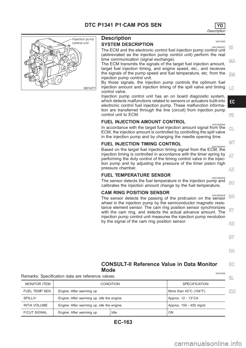
SEF437Y
DescriptionNJEC0693SYSTEM DESCRIPTIONNJEC0693S01The ECM and the electronic control fuel injection pump control unit
(abbreviated as the injection pump control unit) perform the real
time communication (signal exchange).
The ECM transmits the signals of the target fuel injection amount,
target fuel injection timing, and engine speed, etc., and receives
the signals of the pump speed and fuel temperature, etc. from the
injection pump control unit.
By those signals, the injection pump controls the optimum fuel
injection amount and injection timing of the spill valve and timing
control valve.
Injection pump control unit has an on board diagnostic system,
which detects malfunctions related to sensors or actuators built-into
electronic control fuel injection pump. These malfunction informa-
tion are transferred through the line (circuit) from injection pump
control unit to ECM.
FUEL INJECTION AMOUNT CONTROLNJEC0693S02In accordance with the target fuel injection amount signal from the
ECM, the injection amount is controlled by controlling the spill valve
in the injection pump and by changing the needle opening time.
FUEL INJECTION TIMING CONTROLNJEC0693S03Based on the target fuel injection timing signal from the ECM, the
injection timing is controlled in accordance with the timer spring by
performing the duty control of the timing control valve in the injec-
tion pump and by adjusting the pressure of the timer piston high
pressure chamber.
FUEL TEMPERATURE SENSORNJEC0693S04The sensor detects the fuel temperature in the injection pump and
calibrates the injection amount change by the fuel temperature.
CAM RING POSITION SENSORNJEC0693S05The sensor detects the passing of the protrusion on the sensor
wheel in the injection pump by the semiconductor magnetic resis-
tance element sensor. The cam ring position sensor synchronizes
with the cam ring, and detects the actual advance amount. The
injection pump control unit measures the injection pump revolution
by the signal of the cam ring position sensor.
CONSULT-II Reference Value in Data Monitor
Mode
NJEC0694Remarks: Specification data are reference values.
MONITOR ITEM CONDITION SPECIFICATION
FUEL TEMP SEN Engine: After warming up More than 40°C (104°F)
SPILL/V Engine: After warming up, idle the engine. Approx. 12 - 13°CA
INT/A VOLUME Engine: After warming up, idle the engine. Approx. 150 - 450 mg/st
F/CUT SIGNAL Engine: After warming up Idle ON
GI
MA
EM
LC
FE
CL
MT
AT
AX
SU
BR
ST
RS
BT
HA
SC
EL
IDX
DTC P1341 P1·CAM POS SENYD
Description
EC-163
Page 1218 of 3189
MONITOR ITEM CONDITION SPECIFICATION
BARO SEN Ignition switch: ONAltitude
Approx. 0 m (0 ft): Approx. 100.62
kPa (1.0062 bar, 1.026 kg/cm
2,
14.59 psi)
Approx. 1,000 m (3,281 ft): Approx.
88.95 kPa (0.8895 bar, 0.907
kg/cm
2, 12.90 psi)
Approx. 1,500 m (4,922 ft): Approx.
83.16 kPa (0.8316 bar, 0.848
kg/cm
2, 12.06 psi)
Approx. 2,000 m (6,562 ft): Approx.
78.36 kPa (0.7836 bar, 0.799
kg/cm
2, 11.36 psi)
ECM Terminals and Reference ValueNJEC0695Specification data are reference values and are measured between each terminal and ground.
CAUTION:
Do not use ECM ground terminals when measuring input/output voltage. Doing so may result in dam-
age to the ECM’s transistor. Use a ground other than ECM terminals, such as the ground.
TERMI-
NAL
NO.WIRE
COLORITEM CONDITION DATA (DC Voltage)
313 L/WElectronic control fuel
injection pump[Engine is running]
Warm-up condition
Idle speedApproximately 0.1V
314 L/RElectronic control fuel
injection pump[Engine is running]
Warm-up condition
Idle speedApproximately 0.4V
316 PUElectronic control fuel
injection pump[Engine is running]
Warm-up condition
Idle speedApproximately 2.5V
317 PElectronic control fuel
injection pump[Engine is running]
Warm-up condition
Idle speedApproximately 2.5V
On Board Diagnosis LogicNJEC0696This self-diagnosis has the one trip detection logic.
DTC Malfunction is detected when .... Check Items (Possible cause)
P1341
0701An improper voltage signal from cam position
sensor (Built-into electronic control fuel injection
pump) is sent to injection pump control unit.Harness or connectors
(Electronic control fuel injection pump circuit is
open or shorted.)
Electronic control fuel injection pump
SEF817Y
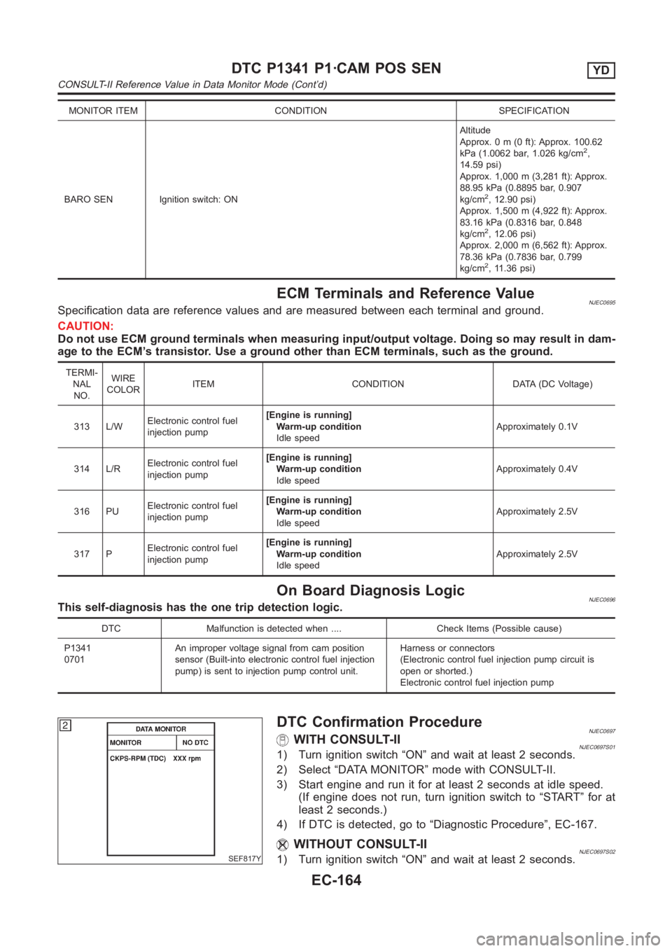
DTC Confirmation ProcedureNJEC0697WITH CONSULT-IINJEC0697S011) Turn ignition switch “ON” and wait at least 2 seconds.
2) Select “DATA MONITOR” mode with CONSULT-II.
3) Start engine and run it for at least 2 seconds at idle speed.
(If engine does not run, turn ignition switch to “START” for at
least 2 seconds.)
4) If DTC is detected, go to “Diagnostic Procedure”, EC-167.
WITHOUT CONSULT-IINJEC0697S021) Turn ignition switch “ON” and wait at least 2 seconds.
DTC P1341 P1·CAM POS SENYD
CONSULT-II Reference Value in Data Monitor Mode (Cont’d)
EC-164
Page 1221 of 3189
Diagnostic ProcedureNJEC0699
1 CHECK ELECTRONIC CONTROL FUEL INJECTION PUMP POWER SUPPLY CIRCUIT
1. Turn ignition switch “OFF”.
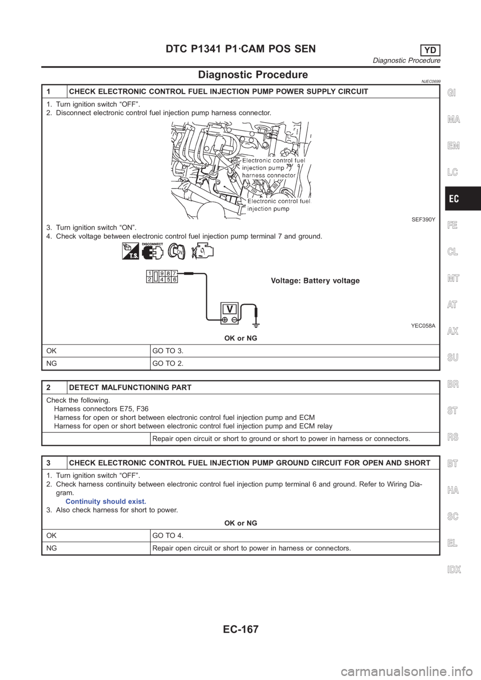
2. Disconnect electronic control fuel injection pump harness connector.
SEF390Y
3. Turn ignition switch “ON”.
4. Check voltage between electronic control fuel injection pump terminal7 and ground.
YEC058A
OK or NG
OK GO TO 3.
NG GO TO 2.
2 DETECT MALFUNCTIONING PART
Check the following.
Harness connectors E75, F36
Harness for open or short between electronic control fuel injection pump and ECM
Harness for open or short between electronic control fuel injection pump and ECM relay
Repair open circuit or short to ground or short to power in harness or connectors.
3 CHECK ELECTRONIC CONTROL FUEL INJECTION PUMP GROUND CIRCUIT FOR OPEN ANDSHORT
1. Turn ignition switch “OFF”.
2. Check harness continuity between electronic control fuel injection pump terminal 6 and ground. Refer to Wiring Dia-
gram.
Continuity should exist.
3. Also check harness for short to power.
OK or NG
OK GO TO 4.
NG Repair open circuit or short to power in harness or connectors.
GI
MA
EM
LC
FE
CL
MT
AT
AX
SU
BR
ST
RS
BT
HA
SC
EL
IDX
DTC P1341 P1·CAM POS SENYD
Diagnostic Procedure
EC-167
Page 1222 of 3189
4 CHECK COMMUNICATION LINE FOR OPEN AND SHORT
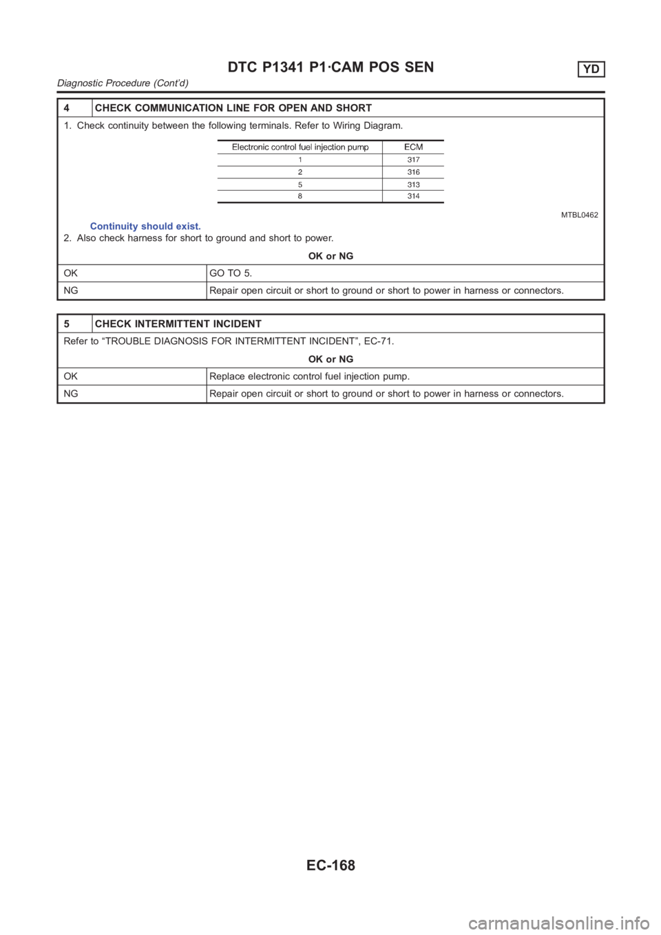
1. Check continuity between the following terminals. Refer to Wiring Diagram.
MTBL0462
Continuity should exist.
2. Also check harness for short to ground and short to power.
OK or NG
OK GO TO 5.
NG Repair open circuit or short to ground or short to power in harness or connectors.
5 CHECK INTERMITTENT INCIDENT
Refer to “TROUBLE DIAGNOSIS FOR INTERMITTENT INCIDENT”, EC-71.
OK or NG
OK Replace electronic control fuel injection pump.
NG Repair open circuit or short to ground or short to power in harness or connectors.
DTC P1341 P1·CAM POS SENYD
Diagnostic Procedure (Cont’d)
EC-168
Page 1223 of 3189
SEF437Y
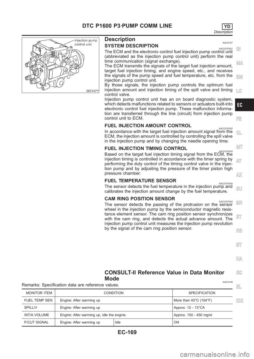
DescriptionNJEC0707SYSTEM DESCRIPTIONNJEC0707S01The ECM and the electronic control fuel injection pump control unit
(abbreviated as the injection pump control unit) perform the real
time communication (signal exchange).
The ECM transmits the signals of the target fuel injection amount,
target fuel injection timing, and engine speed, etc., and receives
the signals of the pump speed and fuel temperature, etc. from the
injection pump control unit.
By those signals, the injection pump controls the optimum fuel
injection amount and injection timing of the spill valve and timing
control valve.
Injection pump control unit has an on board diagnostic system,
which detects malfunctions related to sensors or actuators built-into
electronic control fuel injection pump. These malfunction informa-
tion are transferred through the line (circuit) from injection pump
control unit to ECM.
FUEL INJECTION AMOUNT CONTROLNJEC0707S02In accordance with the target fuel injection amount signal from the
ECM, the injection amount is controlled by controlling the spill valve
in the injection pump and by changing the needle opening time.
FUEL INJECTION TIMING CONTROLNJEC0707S03Based on the target fuel injection timing signal from the ECM, the
injection timing is controlled in accordance with the timer spring by
performing the duty control of the timing control valve in the injec-
tion pump and by adjusting the pressure of the timer piston high
pressure chamber.
FUEL TEMPERATURE SENSORNJEC0707S04The sensor detects the fuel temperature in the injection pump and
calibrates the injection amount change by the fuel temperature.
CAM RING POSITION SENSORNJEC0707S05The sensor detects the passing of the protrusion on the sensor
wheel in the injection pump by the semiconductor magnetic resis-
tance element sensor. The cam ring position sensor synchronizes
with the cam ring, and detects the actual advance amount. The
injection pump control unit measures the injection pump revolution
by the signal of the cam ring position sensor.
CONSULT-II Reference Value in Data Monitor
Mode
NJEC0708Remarks: Specification data are reference values.
MONITOR ITEM CONDITION SPECIFICATION
FUEL TEMP SEN Engine: After warming up More than 40°C (104°F)
SPILL/V Engine: After warming up Approx. 12 - 13°CA
INT/A VOLUME Engine: After warming up, idle the engine. Approx. 150 - 450 mg/st
F/CUT SIGNAL Engine: After warming up Idle ON
GI
MA
EM
LC
FE
CL
MT
AT
AX
SU
BR
ST
RS
BT
HA
SC
EL
IDX
DTC P1600 P3·PUMP COMM LINEYD
Description
EC-169
Page 1224 of 3189
MONITOR ITEM CONDITION SPECIFICATION
BARO SEN Ignition switch: ONAltitude
Approx. 0 m (0 ft): Approx. 100.62
kPa (1.0062 bar, 1.026 kg/cm
2,
14.59 psi)
Approx. 1,000 m (3,281 ft): Approx.
88.95 kPa (0.8895 bar, 0.907
kg/cm
2, 12.90 psi)
Approx. 1,500 m (4,922 ft): Approx.
83.16 kPa (0.8316 bar, 0.848
kg/cm
2, 12.06 psi)
Approx. 2,000 m (6,562 ft): Approx.
78.36 kPa (0.7836 bar, 0.799
kg/cm
2, 11.36 psi)
ECM Terminals and Reference ValueNJEC0709Specification data are reference values and are measured between each terminal and ground.
CAUTION:
Do not use ECM ground terminals when measuring input/output voltage. Doing so may result in dam-
age to the ECM’s transistor. Use a ground other than ECM terminals, such as the ground.
TERMI-
NAL
NO.WIRE
COLORITEM CONDITION DATA (DC Voltage)
313 L/WElectronic control fuel
injection pump[Engine is running]
Warm-up condition
Idle speedApproximately 0.1V
314 L/RElectronic control fuel
injection pump[Engine is running]
Warm-up condition
Idle speedApproximately 0.4V
316 PUElectronic control fuel
injection pump[Engine is running]
Warm-up condition
Idle speedApproximately 2.5V
317 PElectronic control fuel
injection pump[Engine is running]
Warm-up condition
Idle speedApproximately 2.5V
On Board Diagnosis LogicNJEC0710This self-diagnosis has the one trip detection logic.
DTC Malfunction is detected when .... Check Items (Possible cause)
P1600
0703Injection pump control unit receives incorrect volt-
age signal from ECM continuously.Harness or connectors
(Electronic control fuel injection pump circuit is
open or shorted.)
Electronic control fuel injection pump
SEF817Y
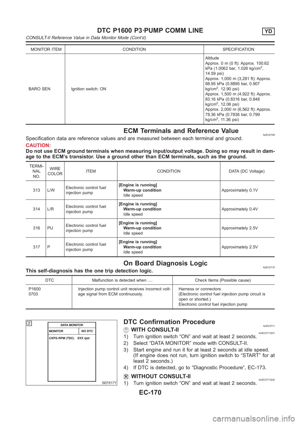
DTC Confirmation ProcedureNJEC0711WITH CONSULT-IINJEC0711S011) Turn ignition switch “ON” and wait at least 2 seconds.
2) Select “DATA MONITOR” mode with CONSULT-II.
3) Start engine and run it for at least 2 seconds at idle speed.
(If engine does not run, turn ignition switch to “START” for at
least 2 seconds.)
4) If DTC is detected, go to “Diagnostic Procedure”, EC-173.
WITHOUT CONSULT-IINJEC0711S021) Turn ignition switch “ON” and wait at least 2 seconds.
DTC P1600 P3·PUMP COMM LINEYD
CONSULT-II Reference Value in Data Monitor Mode (Cont’d)
EC-170
Page 1227 of 3189
Diagnostic ProcedureNJEC0713
1 CHECK ELECTRONIC CONTROL FUEL INJECTION PUMP POWER SUPPLY CIRCUIT
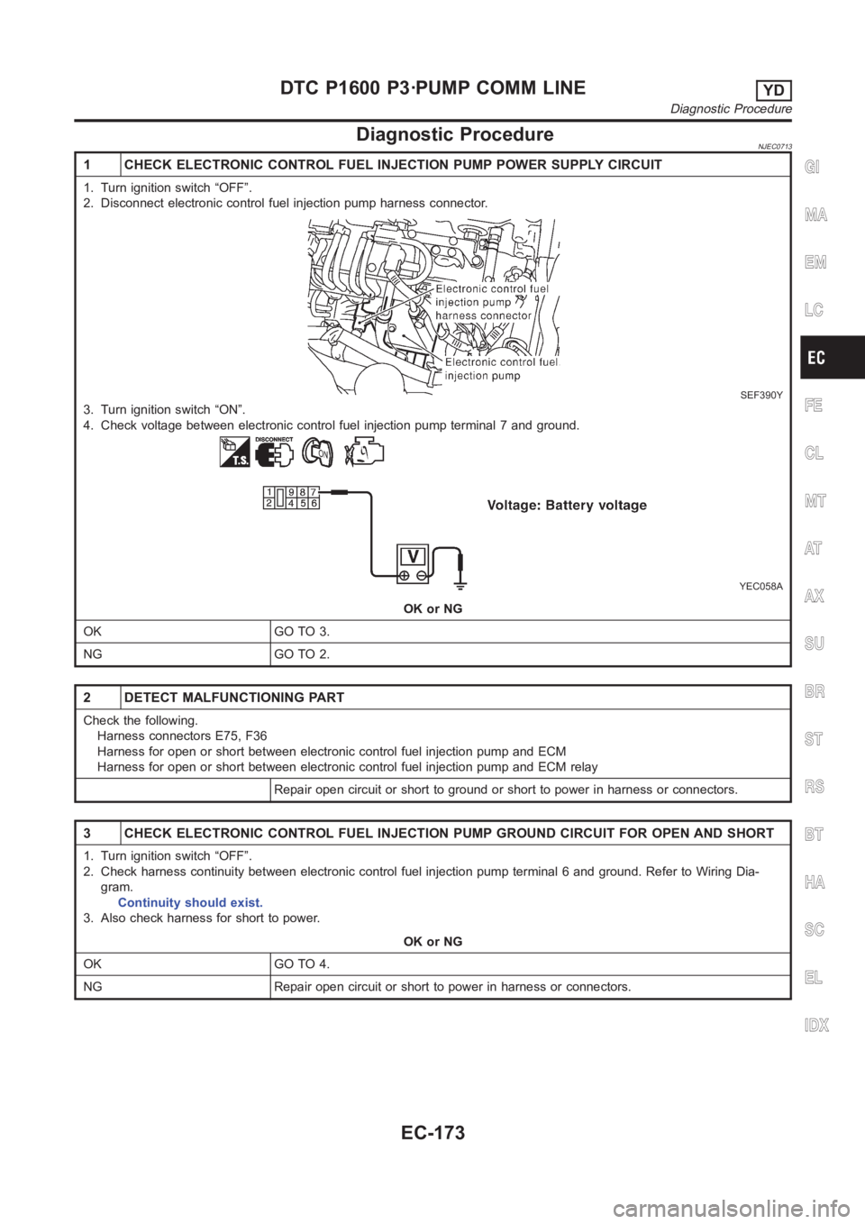
1. Turn ignition switch “OFF”.
2. Disconnect electronic control fuel injection pump harness connector.
SEF390Y
3. Turn ignition switch “ON”.
4. Check voltage between electronic control fuel injection pump terminal7 and ground.
YEC058A
OK or NG
OK GO TO 3.
NG GO TO 2.
2 DETECT MALFUNCTIONING PART
Check the following.
Harness connectors E75, F36
Harness for open or short between electronic control fuel injection pump and ECM
Harness for open or short between electronic control fuel injection pump and ECM relay
Repair open circuit or short to ground or short to power in harness or connectors.
3 CHECK ELECTRONIC CONTROL FUEL INJECTION PUMP GROUND CIRCUIT FOR OPEN ANDSHORT
1. Turn ignition switch “OFF”.
2. Check harness continuity between electronic control fuel injection pump terminal 6 and ground. Refer to Wiring Dia-
gram.
Continuity should exist.
3. Also check harness for short to power.
OK or NG
OK GO TO 4.
NG Repair open circuit or short to power in harness or connectors.
GI
MA
EM
LC
FE
CL
MT
AT
AX
SU
BR
ST
RS
BT
HA
SC
EL
IDX
DTC P1600 P3·PUMP COMM LINEYD
Diagnostic Procedure
EC-173
Page 1228 of 3189
4 CHECK COMMUNICATION LINE FOR OPEN AND SHORT
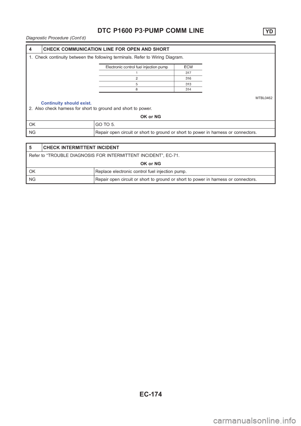
1. Check continuity between the following terminals. Refer to Wiring Diagram.
MTBL0462
Continuity should exist.
2. Also check harness for short to ground and short to power.
OK or NG
OK GO TO 5.
NG Repair open circuit or short to ground or short to power in harness or connectors.
5 CHECK INTERMITTENT INCIDENT
Refer to “TROUBLE DIAGNOSIS FOR INTERMITTENT INCIDENT”, EC-71.
OK or NG
OK Replace electronic control fuel injection pump.
NG Repair open circuit or short to ground or short to power in harness or connectors.
DTC P1600 P3·PUMP COMM LINEYD
Diagnostic Procedure (Cont’d)
EC-174