2003 NISSAN ALMERA N16 coolant level
[x] Cancel search: coolant levelPage 935 of 3189
![NISSAN ALMERA N16 2003 Electronic Repair Manual DTC P1217 ENGINE OVER TEMPERATURE
EC-605
[QG (WITHOUT EURO-OBD)]
C
D
E
F
G
H
I
J
K
L
MA
EC
7.CHECK COOLING FAN MOTORS
Refer to EC-606, "
Component Inspection" .
OK or NG
OK >> GO TO 8.
NG >> R NISSAN ALMERA N16 2003 Electronic Repair Manual DTC P1217 ENGINE OVER TEMPERATURE
EC-605
[QG (WITHOUT EURO-OBD)]
C
D
E
F
G
H
I
J
K
L
MA
EC
7.CHECK COOLING FAN MOTORS
Refer to EC-606, "
Component Inspection" .
OK or NG
OK >> GO TO 8.
NG >> R](/manual-img/5/57350/w960_57350-934.png)
DTC P1217 ENGINE OVER TEMPERATURE
EC-605
[QG (WITHOUT EURO-OBD)]
C
D
E
F
G
H
I
J
K
L
MA
EC
7.CHECK COOLING FAN MOTORS
Refer to EC-606, "
Component Inspection" .
OK or NG
OK >> GO TO 8.
NG >> Replace cooling fan motors.
8.CHECK SMART ENTRANCE CONTROL UNIT
Refer to EL-368.
OK or NG
OK >> GO TO 9.
NG >> Replace cooling fan motors.
9.CHECK INTERMITTENT INCIDENT
Perform EC-485, "
TROUBLE DIAGNOSIS FOR INTERMITTENT INCIDENT" .
>>INSPECTION END
Main 12 Causes of OverheatingEBS00KJ7
*1: Turn the ignition switch ON.
*2: Engine running at 3,000 rpm for 10 minutes.
*3: Drive at 90 km/h (55 MPH) for 30 minutes and then let idle for 10 minutes. Engine Step Inspection item Equipment Standard Reference page
OFF 1
●Blocked radiator
●Blocked condenser
●Blocked radiator grille
●Blocked bumper
●Visual No blocking —
2
●Coolant mixture●Coolant tester 50 - 50% coolant mixture See MA-19.
3
●Coolant level●Visual Coolant up to MAX level
in reservoir tank and radi-
ator filler neckSee MA-7.
4
●Radiator cap●Pressure tester 59 - 98 kPa
(0.59 - 0.98 bar, 0.6 - 1.0
kg/cm
2 , 9 - 14 psi) (Limit)See LC-12.
ON*
25●Coolant leaks●Visual No leaks See LC-11.
ON*
26●Thermostat●Touch the upper and
lower radiator hosesBoth hoses should be hot See LC-15, and LC-16.
ON*
17●Cooling fan●CONSULT-II Operating See trouble diagnosis for
DTC P1217 (EC-596
).
OFF 8
●Combustion gas leak●Color checker chemical
tester 4 Gas analyzerNegative —
ON*
39●Coolant temperature
gauge●Visual Gauge less than 3/4
when driving—
●Coolant overflow to
reservoir tank●Visual No overflow during driving
and idlingSee MA-7.
OFF*
410●Coolant return from
reservoir tank to radia-
tor●Visual Should be initial level in
reservoir tankSee MA-7.
OFF 11
●Cylinder head●Straight gauge feeler
gauge0.1 mm (0.004 in) Maxi-
mum distortion (warping)SeeEM-57, "CYLINDER
HEAD" .
12
●Cylinder block and pis-
tons●Visual No scuffing on cylinder
walls or pistonSeeEM-70, "CYLINDER
BLOCK" .
Page 1185 of 3189
![NISSAN ALMERA N16 2003 Electronic Repair Manual TERMI-
NAL
NO.WIRE
COLORITEM CONDITION DATA(DC Voltage)
221 LG/B Cooling fan relay (High)[Engine is running]
Cooling fans are not operating
Cooling fans are operating at low speedBATTERY VOLTAGE
(11 - NISSAN ALMERA N16 2003 Electronic Repair Manual TERMI-
NAL
NO.WIRE
COLORITEM CONDITION DATA(DC Voltage)
221 LG/B Cooling fan relay (High)[Engine is running]
Cooling fans are not operating
Cooling fans are operating at low speedBATTERY VOLTAGE
(11 -](/manual-img/5/57350/w960_57350-1184.png)
TERMI-
NAL
NO.WIRE
COLORITEM CONDITION DATA(DC Voltage)
221 LG/B Cooling fan relay (High)[Engine is running]
Cooling fans are not operating
Cooling fans are operating at low speedBATTERY VOLTAGE
(11 - 14V)
[Engine is running]
Cooling fans are operating at high speedApproximately 0.1V
On Board Diagnosis LogicNJEC0663This diagnosis continuously monitors the engine coolant temperature.
If the cooling fan or another component in the cooling system malfunctions, engine coolant temperature will
rise.
When the engine coolant temperature reaches an abnormally high temperature condition, a malfunction is
indicated.
This self-diagnosis has the one trip detection logic.
DTC Malfunction is detected when ... Check Items (Possible Cause)
P1217
0208Cooling fan does not operate properly (Overheat).
Cooling fan system does not operate properly
(Overheat).
Engine coolant was not added to the system using
the proper filling method.Harness or connectors
(The cooling fan circuit is open or shorted.)
Cooling fan
Radiator hose
Radiator
Radiator cap
Water pump
Thermostat
Engine coolant temperature sensor
For more information, refer to “MAIN 12 CAUSES OF
OVERHEATING”, EC-144.
CAUTION:
When a malfunction is indicated, be sure to replace the coolant following the procedure in the LC-43,
“Changing Engine Coolant”. Also, replace the engine oil.
1) Fill radiator with coolant up to specified level with a filling speed of 2liters per minute. Be sure
to use coolant with the proper mixture ratio. Refer to MA-21, “Engine Coolant Mixture Ratio”.
2) After refilling coolant, run engine to ensure that no water-flow noise is emitted.
GI
MA
EM
LC
FE
CL
MT
AT
AX
SU
BR
ST
RS
BT
HA
SC
EL
IDX
DTC P1217 OVER HEATYD
ECM Terminals and Reference Value (Cont’d)
EC-131
Page 1186 of 3189
AEC640
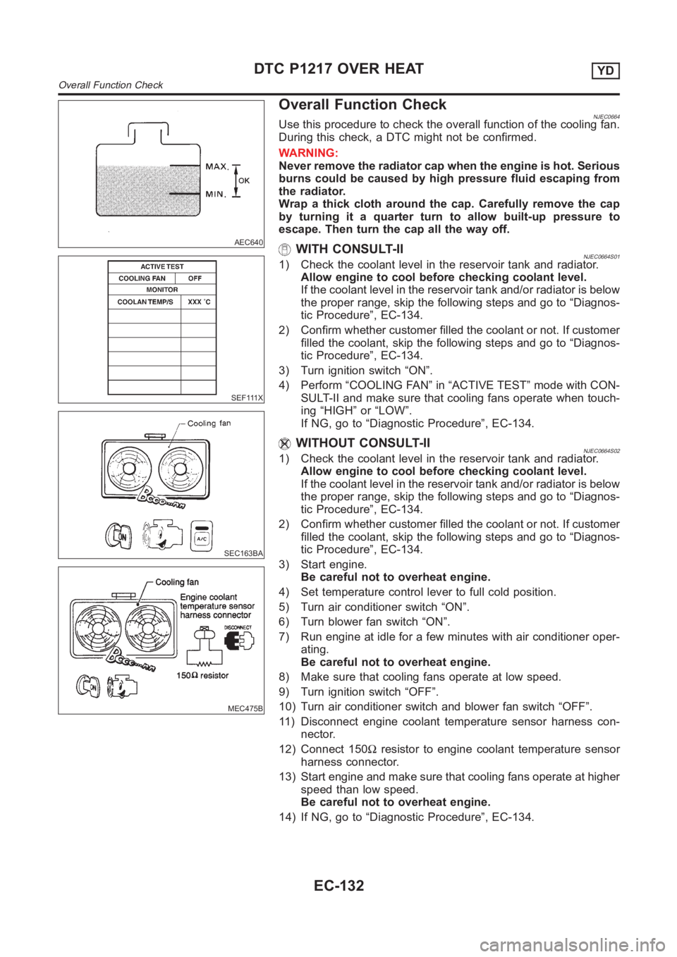
Overall Function Check
SEF111X
SEC163BA
MEC475B
NJEC0664Use this procedure to check the overall function of the cooling fan.
During this check, a DTC might not be confirmed.
WARNING:
Never remove the radiator cap when the engine is hot. Serious
burns could be caused by high pressure fluid escaping from
the radiator.
Wrap a thick cloth around the cap. Carefully remove the cap
by turning it a quarter turn to allow built-up pressure to
escape. Then turn the cap all the way off.
WITH CONSULT-IINJEC0664S011) Check the coolant level in the reservoir tank and radiator.
Allow engine to cool before checking coolant level.
If the coolant level in the reservoir tank and/or radiator is below
the proper range, skip the following steps and go to “Diagnos-
tic Procedure”, EC-134.
2) Confirm whether customer filled the coolant or not. If customer
filled the coolant, skip the following steps and go to “Diagnos-
tic Procedure”, EC-134.
3) Turn ignition switch “ON”.
4) Perform “COOLING FAN” in “ACTIVE TEST” mode with CON-
SULT-II and make sure that cooling fans operate when touch-
ing “HIGH” or “LOW”.
If NG, go to “Diagnostic Procedure”, EC-134.
WITHOUT CONSULT-IINJEC0664S021) Check the coolant level in the reservoir tank and radiator.
Allow engine to cool before checking coolant level.
If the coolant level in the reservoir tank and/or radiator is below
the proper range, skip the following steps and go to “Diagnos-
tic Procedure”, EC-134.
2) Confirm whether customer filled the coolant or not. If customer
filled the coolant, skip the following steps and go to “Diagnos-
tic Procedure”, EC-134.
3) Start engine.
Be careful not to overheat engine.
4) Set temperature control lever to full cold position.
5) Turn air conditioner switch “ON”.
6) Turn blower fan switch “ON”.
7) Run engine at idle for a few minutes with air conditioner oper-
ating.
Be careful not to overheat engine.
8) Make sure that cooling fans operate at low speed.
9) Turn ignition switch “OFF”.
10) Turn air conditioner switch and blower fan switch “OFF”.
11) Disconnect engine coolant temperature sensor harness con-
nector.
12) Connect 150Ωresistor to engine coolant temperature sensor
harness connector.
13) Start engine and make sure that cooling fans operate at higher
speed than low speed.
Be careful not to overheat engine.
14) If NG, go to “Diagnostic Procedure”, EC-134.
DTC P1217 OVER HEATYD
Overall Function Check
EC-132
Page 1198 of 3189
9 CHECK INTERMITTENT INCIDENT
1. Perform “TROUBLE DIAGNOSIS FOR INTERMITTENT INCIDENT”, EC-71.
INSPECTION END
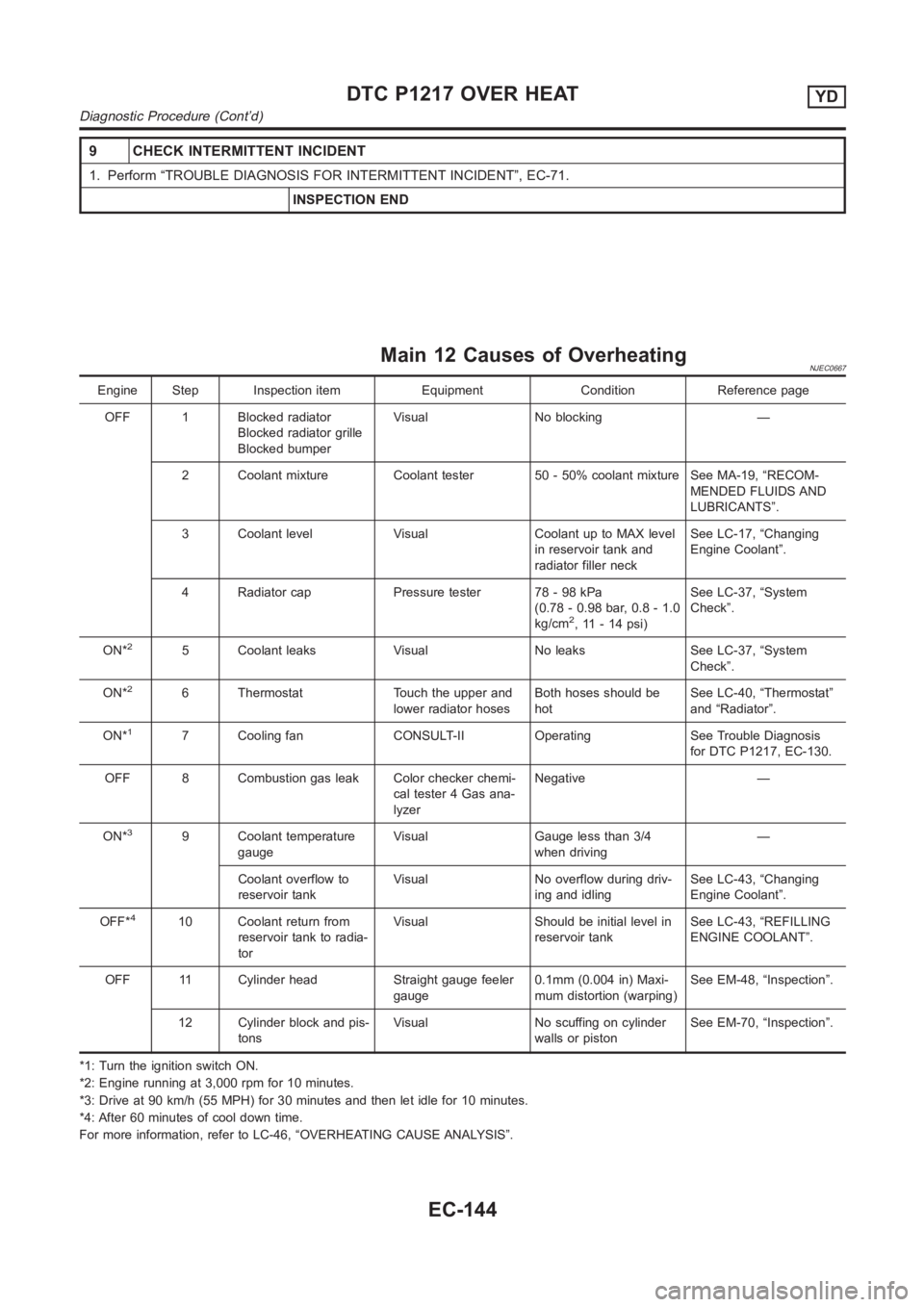
Main 12 Causes of OverheatingNJEC0667
Engine Step Inspection item Equipment Condition Reference page
OFF 1 Blocked radiator
Blocked radiator grille
Blocked bumperVisual No blocking —
2 Coolant mixture Coolant tester 50 - 50% coolant mixture See MA-19, “RECOM-
MENDED FLUIDS AND
LUBRICANTS”.
3 Coolant level Visual Coolant up to MAX level
in reservoir tank and
radiator filler neckSee LC-17, “Changing
Engine Coolant”.
4 Radiator cap Pressure tester 78 - 98 kPa
(0.78 - 0.98 bar, 0.8 - 1.0
kg/cm
2, 11 - 14 psi)See LC-37, “System
Check”.
ON*
25 Coolant leaks Visual No leaks See LC-37, “System
Check”.
ON*
26 Thermostat Touch the upper and
lower radiator hosesBoth hoses should be
hotSee LC-40, “Thermostat”
and “Radiator”.
ON*
17 Cooling fan CONSULT-II Operating See Trouble Diagnosis
for DTC P1217, EC-130.
OFF 8 Combustion gas leak Color checker chemi-
cal tester 4 Gas ana-
lyzerNegative —
ON*
39 Coolant temperature
gaugeVisual Gauge less than 3/4
when driving—
Coolant overflow to
reservoir tankVisual No overflow during driv-
ing and idlingSee LC-43, “Changing
Engine Coolant”.
OFF*
410 Coolant return from
reservoir tank to radia-
torVisual Should be initial level in
reservoir tankSee LC-43, “REFILLING
ENGINE COOLANT”.
OFF 11 Cylinder head Straight gauge feeler
gauge0.1mm (0.004 in) Maxi-
mum distortion (warping)See EM-48, “Inspection”.
12 Cylinder block and pis-
tonsVisual No scuffing on cylinder
walls or pistonSee EM-70, “Inspection”.
*1: Turn the ignition switch ON.
*2: Engine running at 3,000 rpm for 10 minutes.
*3: Drive at 90 km/h (55 MPH) for 30 minutes and then let idle for 10 minutes.
*4: After 60 minutes of cool down time.
For more information, refer to LC-46, “OVERHEATING CAUSE ANALYSIS”.
DTC P1217 OVER HEATYD
Diagnostic Procedure (Cont’d)
EC-144
Page 2164 of 3189
SMA525A
On-vehicle Service
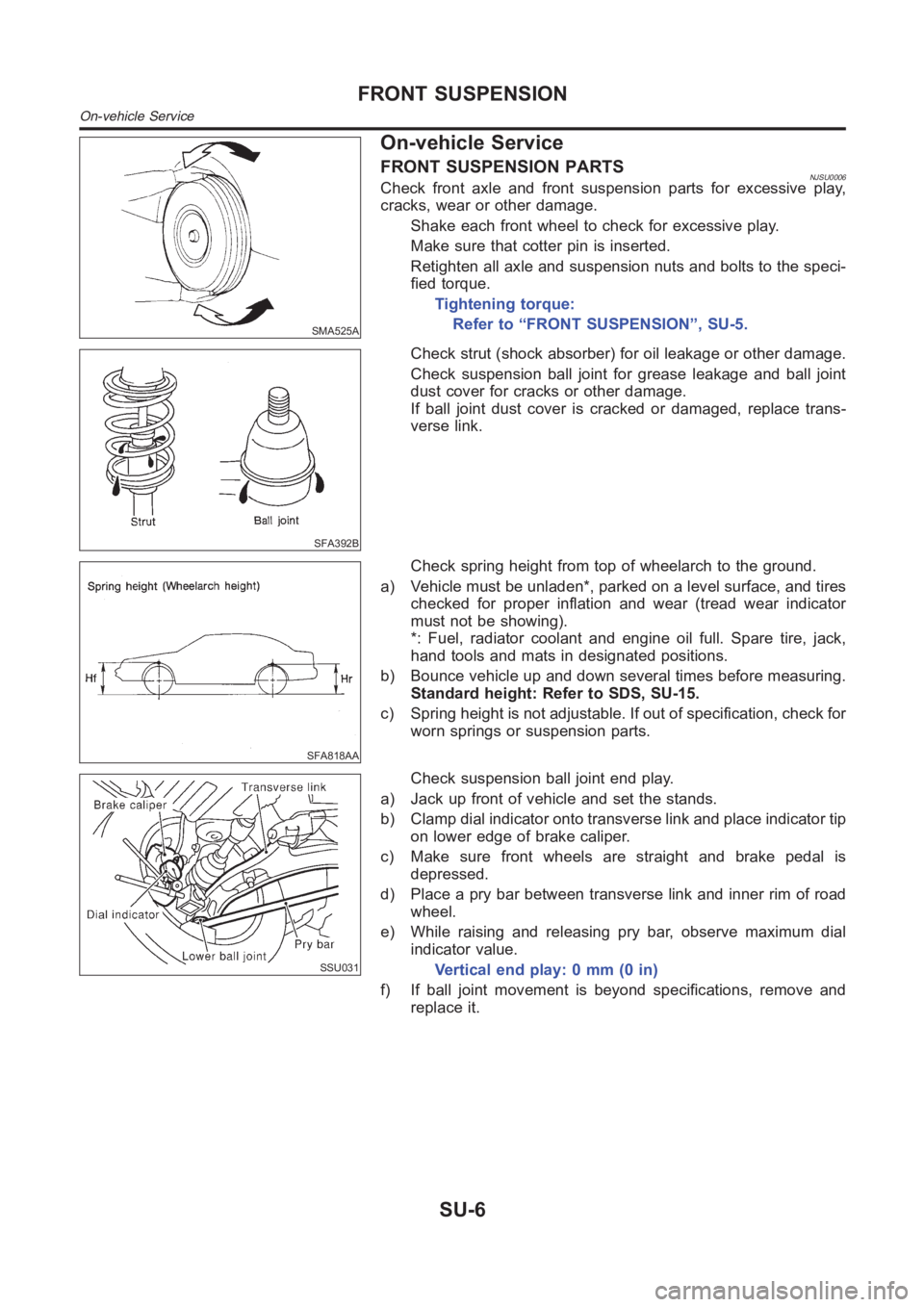
FRONT SUSPENSION PARTSNJSU0006Check front axle and front suspension parts for excessive play,
cracks, wear or other damage.
Shake each front wheel to check for excessive play.
Make sure that cotter pin is inserted.
Retighten all axle and suspension nuts and bolts to the speci-
fied torque.
Tightening torque:
Refer to “FRONT SUSPENSION”, SU-5.
SFA392B
Check strut (shock absorber) for oil leakage or other damage.
Check suspension ball joint for grease leakage and ball joint
dust cover for cracks or other damage.
If ball joint dust cover is cracked or damaged, replace trans-
verse link.
SFA818AA
Check spring height from top of wheelarch to the ground.
a) Vehicle must be unladen*, parked on a level surface, and tires
checked for proper inflation and wear (tread wear indicator
must not be showing).
*: Fuel, radiator coolant and engine oil full. Spare tire, jack,
hand tools and mats in designated positions.
b) Bounce vehicle up and down several times before measuring.
Standard height: Refer to SDS, SU-15.
c) Spring height is not adjustable. If out of specification, check for
worn springs or suspension parts.
SSU031
Check suspension ball joint end play.
a) Jack up front of vehicle and set the stands.
b) Clamp dial indicator onto transverse link and place indicator tip
on lower edge of brake caliper.
c) Make sure front wheels are straight and brake pedal is
depressed.
d) Place a pry bar between transverse link and inner rim of road
wheel.
e) While raising and releasing pry bar, observe maximum dial
indicator value.
Vertical end play: 0 mm (0 in)
f) If ball joint movement is beyond specifications, remove and
replace it.
FRONT SUSPENSION
On-vehicle Service
SU-6
Page 2380 of 3189
YEL809D
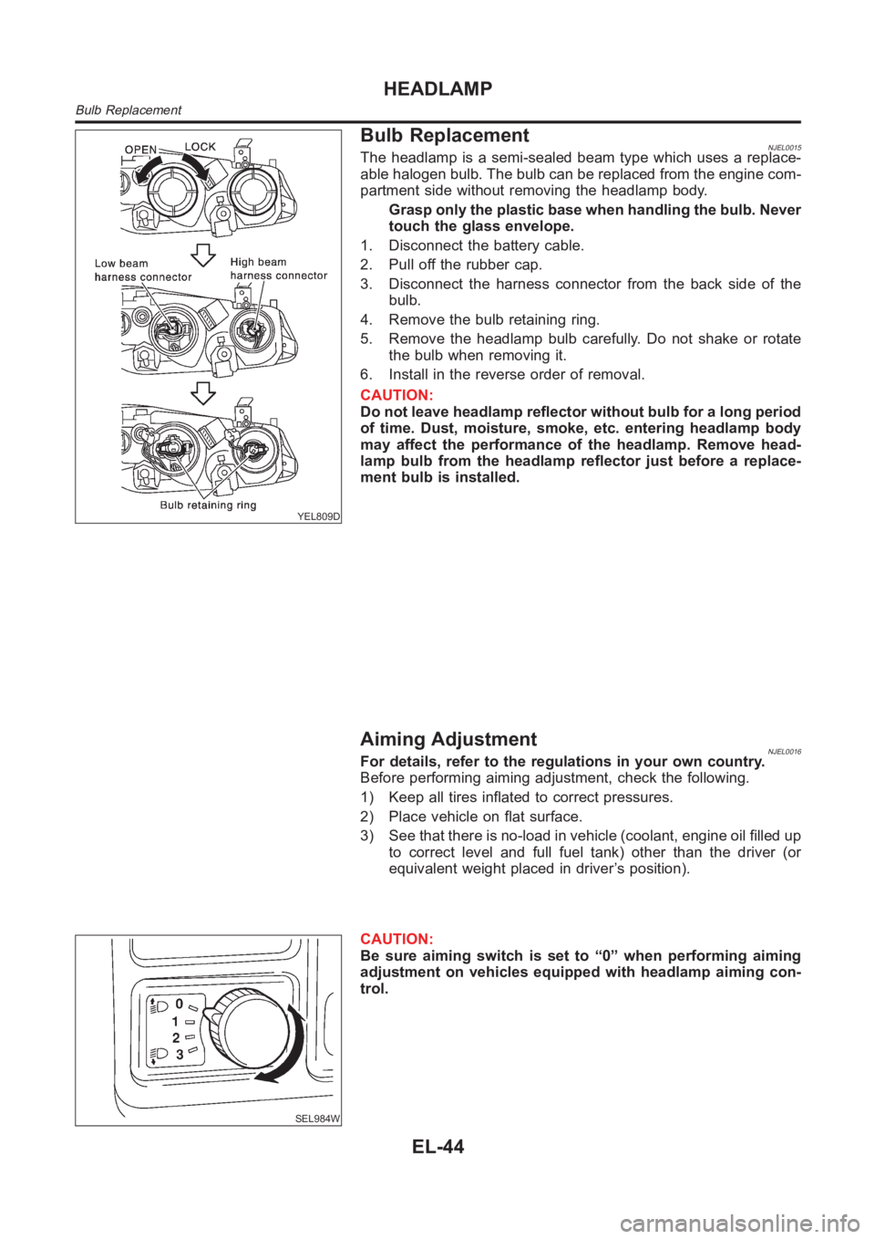
Bulb ReplacementNJEL0015The headlamp is a semi-sealed beam type which uses a replace-
able halogen bulb. The bulb can be replaced from the engine com-
partment side without removing the headlamp body.
Grasp only the plastic base when handling the bulb. Never
touch the glass envelope.
1. Disconnect the battery cable.
2. Pull off the rubber cap.
3. Disconnect the harness connector from the back side of the
bulb.
4. Remove the bulb retaining ring.
5. Remove the headlamp bulb carefully. Do not shake or rotate
the bulb when removing it.
6. Install in the reverse order of removal.
CAUTION:
Do not leave headlamp reflector without bulb for a long period
of time. Dust, moisture, smoke, etc. entering headlamp body
may affect the performance of the headlamp. Remove head-
lamp bulb from the headlamp reflector just before a replace-
ment bulb is installed.
Aiming AdjustmentNJEL0016For details, refer to the regulations in your own country.
Before performing aiming adjustment, check the following.
1) Keep all tires inflated to correct pressures.
2) Place vehicle on flat surface.
3) See that there is no-load in vehicle (coolant, engine oil filled up
to correct level and full fuel tank) other than the driver (or
equivalent weight placed in driver’s position).
SEL984W
CAUTION:
Be sure aiming switch is set to “0” when performing aiming
adjustment on vehicles equipped with headlamp aiming con-
trol.
HEADLAMP
Bulb Replacement
EL-44
Page 2400 of 3189
YEL812D
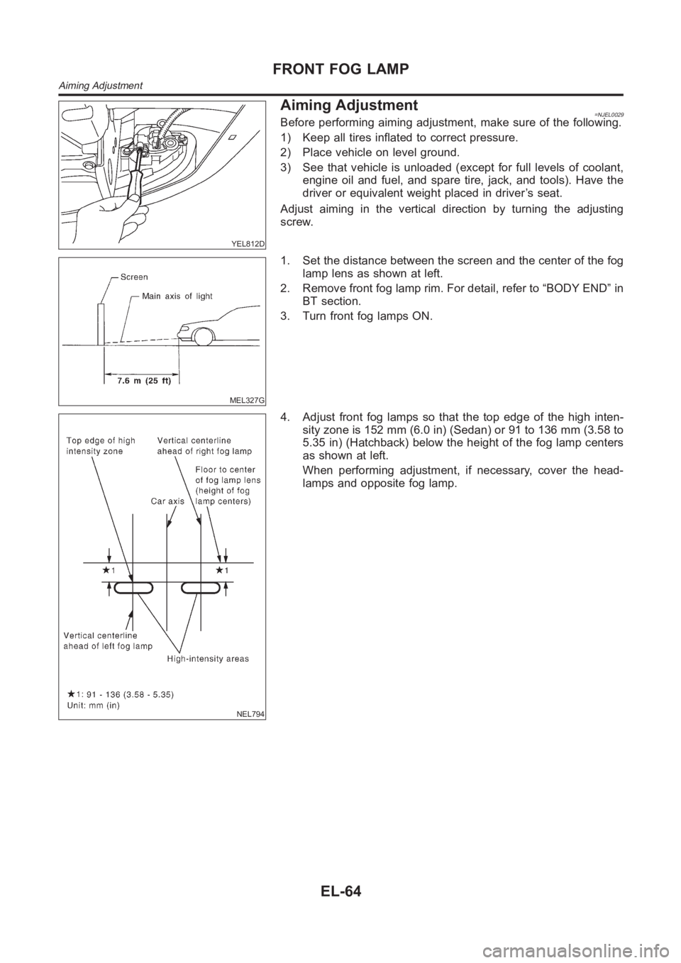
Aiming Adjustment=NJEL0029Before performing aiming adjustment, make sure of the following.
1) Keep all tires inflated to correct pressure.
2) Place vehicle on level ground.
3) See that vehicle is unloaded (except for full levels of coolant,
engine oil and fuel, and spare tire, jack, and tools). Have the
driver or equivalent weight placed in driver’s seat.
Adjust aiming in the vertical direction by turning the adjusting
screw.
MEL327G
1. Set the distance between the screen and the center of the fog
lamp lens as shown at left.
2. Remove front fog lamp rim. For detail, refer to “BODY END” in
BT section.
3. Turn front fog lamps ON.
NEL794
4. Adjust front fog lamps so that the top edge of the high inten-
sity zone is 152 mm (6.0 in) (Sedan) or 91 to 136 mm (3.58 to
5.35 in) (Hatchback) below the height of the fog lamp centers
as shown at left.
When performing adjustment, if necessary, cover the head-
lamps and opposite fog lamp.
FRONT FOG LAMP
Aiming Adjustment
EL-64
Page 2447 of 3189
WATER TEMPERATURE GAUGE (QG AND YD ENGINE MODELS WITH COMMON RAIL)NJEL0442S09The water temperature gauge indicates the engine coolant temperature.
ECM provides a engine coolant temperature signal to combination meter forwater temperature gauge with
CAN communication line.
WATER TEMPERATURE GAUGE (YD ENGINE MODELS WITHOUT COMMON RAIL)NJEL0442S04The water temperature gauge indicates the engine coolant temperature. The reading on the gauge is based
on the resistance of the thermal transmitter.
As the temperature of the coolant increases, the resistance of the thermaltransmitter decreases. A variable
ground is supplied to terminal 35 of the combination meter for the water temperature gauge. The needle on
the gauge moves from “C” to “H”.
TACHOMETER (QG AND YD ENGINE MODELS WITH COMMON RAIL)NJEL0442S10The tachometer indicates engine speed in revolution per minutes (rpm). ECM provides an engine speed sig-
nal to combination meter for tachometer with CAN communication line.
TACHOMETER (YD ENGINE MODELS WITHOUT COMMON RAIL)NJEL0442S05The tachometer indicates engine speed in revolutions per minute (rpm).
The tachometer is regulated by a signal
from terminal 32 (Gasoline engine models) or 439 (Diesel engine models) ofthe ECM
to combination meter terminal 53 for the tachometer.
FUEL GAUGENJEL0442S06The fuel gauge indicates the approximate fuel level in the fuel tank.
The fuel gauge is regulated by a variable ground signal supplied
from body grounds F118 (QG engine models), M28 and M67
through terminals 33 and 32 of combination meter,
through terminal 1 of the fuel level sensor unit and
through terminal 4 of the fuel level sensor unit
to combination meter terminal 34 for the fuel gauge.
SPEEDOMETER (MODELS WITH ABS)NJEL0442S11The combination meter receives a signal from the ABS actuator and electricunit. The speedometer converts
the signal into the vehicle speed displayed.
SPEEDOMETER (MODELS WITHOUT ABS)NJEL0442S07The combination meter provides a voltage signal to the vehicle speed sensor for the speedometer.
The voltage is supplied
from combination meter terminal 13 for the speedometer
to terminal 1 of the vehicle speed sensor.
Ground is supplied
from body grounds F118 (QG engine models), M28 and M67
through terminals 32 and 14 of combination meter
to teminal 2 of the vehicle speed sensor.
The speedometer converts the voltage into the vehicle speed displayed.
GI
MA
EM
LC
EC
FE
CL
MT
AT
AX
SU
BR
ST
RS
BT
HA
SC
IDX
METERS AND GAUGES
System Description (Cont’d)
EL-111