Page 1566 of 3189
![NISSAN ALMERA N16 2003 Electronic Repair Manual AT-110
[EURO-OBD]
CAN COMMUNICATION
TYPE 2
System diagram
Input/output signal chart
T: Transmit R: Receive Vehicle speed signal R T
Seat belt reminder signalRT
Headlamp switch signalTR
Flashing indi](/manual-img/5/57350/w960_57350-1565.png "NISSAN ALMERA N16 2003 Electronic Repair Manual AT-110
[EURO-OBD]
CAN COMMUNICATION
TYPE 2
System diagram
Input/output signal chart
T: Transmit R: Receive Vehicle speed signal R T
Seat belt reminder signalRT
Headlamp switch signalTR
Flashing indi")
AT-110
[EURO-OBD]
CAN COMMUNICATION
TYPE 2
System diagram
Input/output signal chart
T: Transmit R: Receive Vehicle speed signal R T
Seat belt reminder signalRT
Headlamp switch signalTR
Flashing indicator signalTR
Engine cooling fan speed signal T R
Child lock indicator signalTR
Door switches state signalTR
A/C compressor signal T R
Accelerator pedal position signal T R
Output shaft revolution signal R T
OD OFF switch signal R T
OD OFF indicator signal T R
A/T self-diagnosis signal R TSignals ECM TCMSmart entrance
control unitCombination meter
SEL826Y
Signals ECMSmart entrance control
unitCombination meter
Engine speed signal T R
Rear window defogger signal R T
Heater fan switch signal R T
Air conditioner switch signal R T
MI signal T R
Engine coolant temperature signal T R
Fuel consumption signal T R
Vehicle speed signal R T
Seat belt reminder signal R T
Headlamp switch signal T R
Flashing indicator signal T R
Engine cooling fan speed signal T R
Child lock indicator signal T R
Door switches state signal T R
A/C compressor signal T R
Page 1667 of 3189
![NISSAN ALMERA N16 2003 Electronic Repair Manual TROUBLE DIAGNOSES FOR SYMPTOMS
AT-211
[EURO-OBD]
D
E
F
G
H
I
J
K
L
MA
B
AT
1. O/D OFF Indicator Lamp Does Not Come OnECS007Q2
SYMPTOM:
O/D OFF indicator lamp does not come on for about 2 seconds when](/manual-img/5/57350/w960_57350-1666.png "NISSAN ALMERA N16 2003 Electronic Repair Manual TROUBLE DIAGNOSES FOR SYMPTOMS
AT-211
[EURO-OBD]
D
E
F
G
H
I
J
K
L
MA
B
AT
1. O/D OFF Indicator Lamp Does Not Come OnECS007Q2
SYMPTOM:
O/D OFF indicator lamp does not come on for about 2 seconds when")
TROUBLE DIAGNOSES FOR SYMPTOMS
AT-211
[EURO-OBD]
D
E
F
G
H
I
J
K
L
MA
B
AT
1. O/D OFF Indicator Lamp Does Not Come OnECS007Q2
SYMPTOM:
O/D OFF indicator lamp does not come on for about 2 seconds when turning ignition switch to “ON”.
1.CHECK GROUND CIRCUIT
1. Turn ignition switch to “OFF” position.
2. Disconnect A/T device harness connector.
3. Check continuity between A/T device terminals 7 and ground.
If OK, check harness for short to ground and short to power.
OK or NG
OK >> GO TO 2
NG >> Repair open circuit or short to ground or short to power
in harness or connectors.
2.CHECK LAMP CIRCUIT
1. Turn ignition switch to “ON” position.
(Do not start engine.)
2. Disconnect A/T device harness connector.
3. Check voltage between A/T device terminals 8 and ground.
OK or NG
OK >> GO TO 3
NG >> Check the following items:
●Harness for short or open between combination
meter terminals 47 and A/T device terminals 8.
3.CHECK OVERDRIVE CONTROL SWITCH
1. Disconnect A/T device harness connector.
2. Check continuity between A/T device terminals 7 and 8.
OK or NG
OK >>INSPECTION END.
NG >> Repair or replace A/T device.Continuity should exist.
MCIB0007E
Voltage: Battery voltage
MCIB0008E
OVERDRIVE CONTROL SW “ON”: Continuity should not exist.
OVERDRIVE CONTROL SW “OFF”: Continuity should exist.
Page 1761 of 3189
![NISSAN ALMERA N16 2003 Electronic Repair Manual CAN COMMUNICATION
AT-305
[EXC.F/EURO-OBD]
D
E
F
G
H
I
J
K
L
MA
B
AT
CAN COMMUNICATIONPFP:23710
System DescriptionECS007QX
CAN (Controller Area Network) is a serial communication line for real time app](/manual-img/5/57350/w960_57350-1760.png "NISSAN ALMERA N16 2003 Electronic Repair Manual CAN COMMUNICATION
AT-305
[EXC.F/EURO-OBD]
D
E
F
G
H
I
J
K
L
MA
B
AT
CAN COMMUNICATIONPFP:23710
System DescriptionECS007QX
CAN (Controller Area Network) is a serial communication line for real time app")
CAN COMMUNICATION
AT-305
[EXC.F/EURO-OBD]
D
E
F
G
H
I
J
K
L
MA
B
AT
CAN COMMUNICATIONPFP:23710
System DescriptionECS007QX
CAN (Controller Area Network) is a serial communication line for real time application. It is an on-vehicle mul-
tiplex communication line with high data communication speed and excellent error detection ability. Many elec-
tronic control units are equipped onto a vehicle, and each control unit shares information and links with other
control units during operation (not independent). In CAN communication, control units are connected with 2
communication lines (CAN H line, CAN L line) allowing a high rate of information transmission with less wiring.
Each control unit transmits/receives data but selectively reads required data only.
CAN Communication UnitECS007QY
×:Applicable
TYPE 1
System diagram
Input/output signal chart
T: Transmit R: Receive Body type Sedan/ 5DH/B/ 3DH/B
Axle2WD
Engine QG18DE QG15DE/QG18DE
Transmission A/T M/T
Brake controlABS
CAN communication unit
ECM××
TCM×
Smart entrance control unit××
Data link connector××
Combination meter××
CAN communication type AT-305, "
TYPE 1"AT- 3 0 6 , "TYPE 2"
SEL825Y
Signals ECM TCMSmart entrance
control unitCombination meter
Engine speed signal T R
Brake switch signal R T
Rear window defogger signal R T
Heater fan switch signal R T
Air conditioner switch signal R T
MI signal T R
Current gear position signal T R
Engine coolant temperature signal T R
Fuel consumption signal T R
Page 1762 of 3189
![NISSAN ALMERA N16 2003 Electronic Repair Manual AT-306
[EXC.F/EURO-OBD]
CAN COMMUNICATION
TYPE 2
System diagram
Input/output signal chart
T: Transmit R: Receive Vehicle speed signal R T
Seat belt reminder signalRT
Headlamp switch signalTR
Flashin](/manual-img/5/57350/w960_57350-1761.png "NISSAN ALMERA N16 2003 Electronic Repair Manual AT-306
[EXC.F/EURO-OBD]
CAN COMMUNICATION
TYPE 2
System diagram
Input/output signal chart
T: Transmit R: Receive Vehicle speed signal R T
Seat belt reminder signalRT
Headlamp switch signalTR
Flashin")
AT-306
[EXC.F/EURO-OBD]
CAN COMMUNICATION
TYPE 2
System diagram
Input/output signal chart
T: Transmit R: Receive Vehicle speed signal R T
Seat belt reminder signalRT
Headlamp switch signalTR
Flashing indicator signalTR
Engine cooling fan speed signal T R
Child lock indicator signalTR
Door switches state signalTR
A/C compressor signal T R
Accelerator pedal position signal T R
Output shaft revolution signal R T
OD OFF switch signal R T
OD OFF indicator signal T R
A/T self-diagnosis signal R TSignals ECM TCMSmart entrance
control unitCombination meter
SEL826Y
Signals ECMSmart entrance control
unitCombination meter
Engine speed signal T R
Rear window defogger signal R T
Heater fan switch signal R T
Air conditioner switch signal R T
MI signal T R
Engine coolant temperature signal T R
Fuel consumption signal T R
Vehicle speed signal R T
Seat belt reminder signal R T
Headlamp switch signal T R
Flashing indicator signal T R
Engine cooling fan speed signal T R
Child lock indicator signal T R
Door switches state signal T R
A/C compressor signal T R
Page 2060 of 3189
ATC-80
TROUBLE DIAGNOSIS
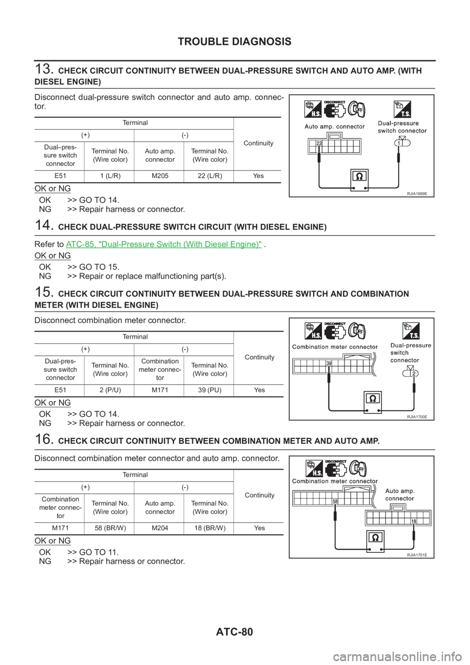
13. CHECK CIRCUIT CONTINUITY BETWEEN DUAL-PRESSURE SWITCH AND AUTO AMP. (WITH
DIESEL ENGINE)
Disconnect dual-pressure switch connector and auto amp. connec-
tor.
OK or NG
OK >> GO TO 14.
NG >> Repair harness or connector.
14. CHECK DUAL-PRESSURE SWITCH CIRCUIT (WITH DIESEL ENGINE)
Refer to AT C - 8 5 , "
Dual-Pressure Switch (With Diesel Engine)" .
OK or NG
OK >> GO TO 15.
NG >> Repair or replace malfunctioning part(s).
15. CHECK CIRCUIT CONTINUITY BETWEEN DUAL-PRESSURE SWITCH AND COMBINATION
METER (WITH DIESEL ENGINE)
Disconnect combination meter connector.
OK or NG
OK >> GO TO 14.
NG >> Repair harness or connector.
16. CHECK CIRCUIT CONTINUITY BETWEEN COMBINATION METER AND AUTO AMP.
Disconnect combination meter connector and auto amp. connector.
OK or NG
OK >> GO TO 11.
NG >> Repair harness or connector.
Terminal
Continuity (+) (-)
Dual–pres-
sure switch
connectorTe r m i n a l N o .
(Wire color)Auto amp.
connectorTerminal No.
(Wire color)
E51 1 (L/R) M205 22 (L/R) Yes
RJIA1699E
Terminal
Continuity (+) (-)
Dual-pres-
sure switch
connectorTe r m i n a l N o .
(Wire color)Combination
meter connec-
torTerminal No.
(Wire color)
E51 2 (P/U) M171 39 (PU) Yes
RJIA1700E
Terminal
Continuity (+) (-)
Combination
meter connec-
torTe r m i n a l N o .
(Wire color)Auto amp.
connectorTerminal No.
(Wire color)
M171 58 (BR/W) M204 18 (BR/W) Yes
RJIA1701E
Page 2061 of 3189
TROUBLE DIAGNOSIS
ATC-81
C
D
E
F
G
H
I
K
L
MA
B
AT C
17.CHECK CIRCUIT CONTINUITY BETWEEN COMBINATION METER AND AUTO AMP.
Disconnect combination meter connector and auto amp. connector.
OK or NG
OK >> GO TO 11.
NG >> Repair harness or connector.
18.CHECK CIRCUIT CONTINUITY BETWEEN COMBINATION METER AND AUTO AMP. (WITH GASO-
LINE ENGINE)
Disconnect combination meter connector and auto amp. connector.
OK or NG
OK >> GO TO 11.
NG >> Repair harness or connector.
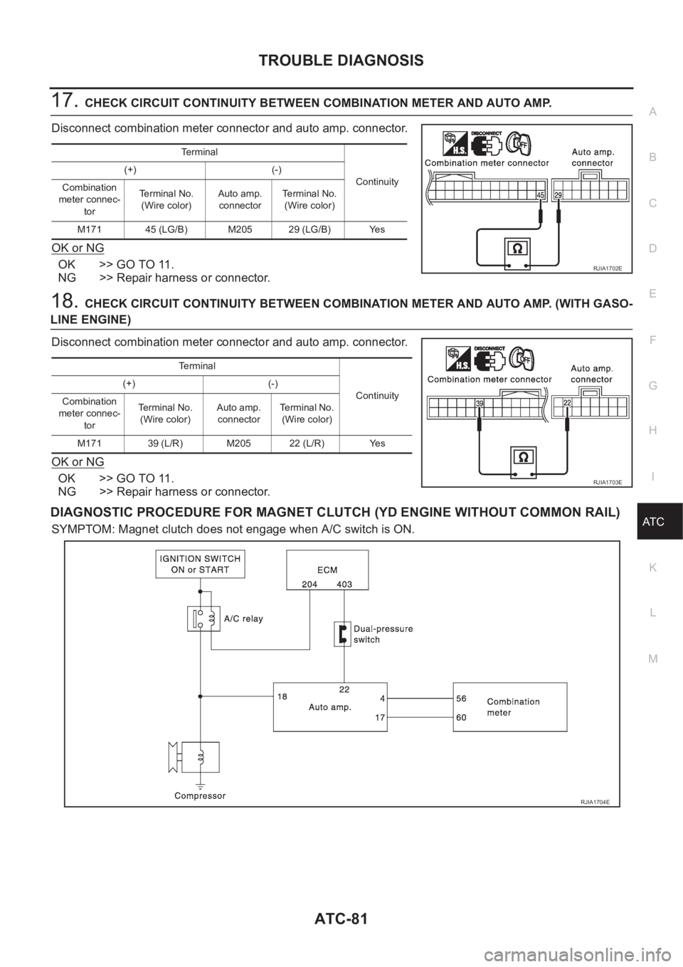
DIAGNOSTIC PROCEDURE FOR MAGNET CLUTCH (YD ENGINE WITHOUT COMMON RAIL)
SYMPTOM: Magnet clutch does not engage when A/C switch is ON.
Terminal
Continuity (+) (-)
Combination
meter connec-
torTerminal No.
(Wire color)Auto amp.
connectorTerminal No.
(Wire color)
M171 45 (LG/B) M205 29 (LG/B) Yes
RJIA1702E
Terminal
Continuity (+) (-)
Combination
meter connec-
torTerminal No.
(Wire color)Auto amp.
connectorTerminal No.
(Wire color)
M171 39 (L/R) M205 22 (L/R) Yes
RJIA1703E
RJIA1704E
Page 2188 of 3189
Precautions When Working On ABSNJBR0140Use recommended tyres in combination with ABS.
Please fit tyres or studded tyres, etc. with the same size.
If different sizes of tyres, or tyres other than the ones rec-
ommended for use with the ABS, are fitted, stopping dis-
tance will increase and control and stability could deterio-
rate.
When changing brake pads, please use Nissan genuine
parts.
When fitting radios etc, do not position the radio itself,
antenna, or antenna cables within an area of about 100
mm (3.94 in) of the control unit.
When doing any work that requires electro-welding, first
remove the control unit.
Please take care when taking a power supply for the
audio, lamps etc., not to take this from any ABS-related
harness. (Please refer to the electrical wiring diagrams for
ABS-related harnesses)
Wiring Diagrams and Trouble DiagnosisNJBR0003When you read wiring diagrams, refer to the following:
GI-12, “HOW TO READ WIRING DIAGRAMS”
EL-12, “POWER SUPPLY ROUTING”
When you perform trouble diagnosis, refer to the following:
GI-33, “HOW TO FOLLOW TEST GROUPS IN TROUBLE DIAGNOSIS”
GI-22, “HOW TO PERFORM EFFICIENT DIAGNOSIS FOR AN ELECTRICAL INCIDENT”
On board self-diagnosis is available everywhere except for Europe.
PRECAUTIONS
Precautions When Working On ABS
BR-4
Page 2249 of 3189
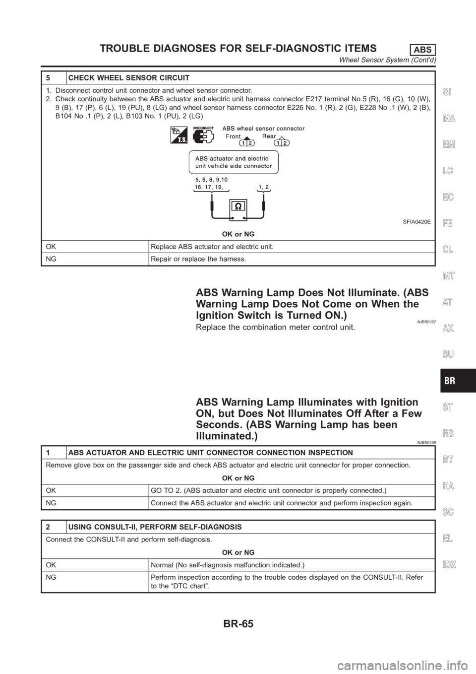
5 CHECK WHEEL SENSOR CIRCUIT
1. Disconnect control unit connector and wheel sensor connector.
2. Check continuity between the ABS actuator and electric unit harness connector E217 terminal No.5 (R), 16 (G), 10 (W),
9 (B), 17 (P), 6 (L), 19 (PU), 8 (LG) and wheel sensor harness connector E226 No. 1 (R), 2 (G), E228 No .1 (W), 2 (B),
B104 No .1 (P), 2 (L), B103 No. 1 (PU), 2 (LG)
SFIA0420E
OK or NG
OK Replace ABS actuator and electric unit.
NG Repair or replace the harness.
ABS Warning Lamp Does Not Illuminate. (ABS
Warning Lamp Does Not Come on When the
Ignition Switch is Turned ON.)
NJBR0167Replace the combination meter control unit.
ABS Warning Lamp Illuminates with Ignition
ON, but Does Not Illuminates Off After a Few
Seconds. (ABS Warning Lamp has been
Illuminated.)
NJBR0168
1 ABS ACTUATOR AND ELECTRIC UNIT CONNECTOR CONNECTION INSPECTION
Remove glove box on the passenger side and check ABS actuator and electric unit connector for proper connection.
OK or NG
OK GO TO 2. (ABS actuator and electric unit connector is properly connected.)
NG Connect the ABS actuator and electric unit connector and perform inspection again.
2 USING CONSULT-II, PERFORM SELF-DIAGNOSIS
Connect the CONSULT-II and perform self-diagnosis.
OK or NG
OK Normal (No self-diagnosis malfunction indicated.)
NG Perform inspection according to the trouble codes displayed on the CONSULT-II. Refer
to the “DTC chart”.
GI
MA
EM
LC
EC
FE
CL
MT
AT
AX
SU
ST
RS
BT
HA
SC
EL
IDX
TROUBLE DIAGNOSES FOR SELF-DIAGNOSTIC ITEMSABS
Wheel Sensor System (Cont’d)
BR-65