Page 2458 of 3189
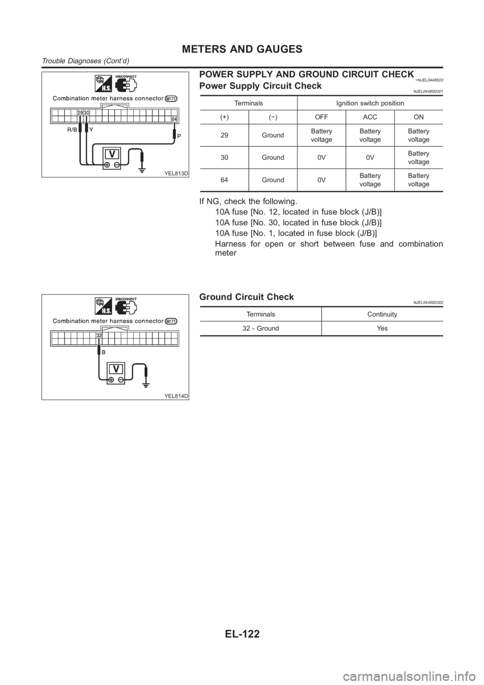
YEL813D
POWER SUPPLY AND GROUND CIRCUIT CHECK=NJEL0448S03Power Supply Circuit CheckNJEL0448S0301
Terminals Ignition switch position
(+) (−) OFF ACC ON
29 GroundBattery
voltageBattery
voltageBattery
voltage
30 Ground 0V 0VBattery
voltage
64 Ground 0VBattery
voltageBattery
voltage
If NG, check the following.
10A fuse [No. 12, located in fuse block (J/B)]
10A fuse [No. 30, located in fuse block (J/B)]
10A fuse [No. 1, located in fuse block (J/B)]
Harness for open or short between fuse and combination
meter
YEL814D
Ground Circuit CheckNJEL0448S0302
Terminals Continuity
32 - Ground Yes
METERS AND GAUGES
Trouble Diagnoses (Cont’d)
EL-122
Page 2459 of 3189
INSPECTION/VEHICLE SPEED SIGNAL=NJEL0448S04Models without ABSNJEL0448S0401
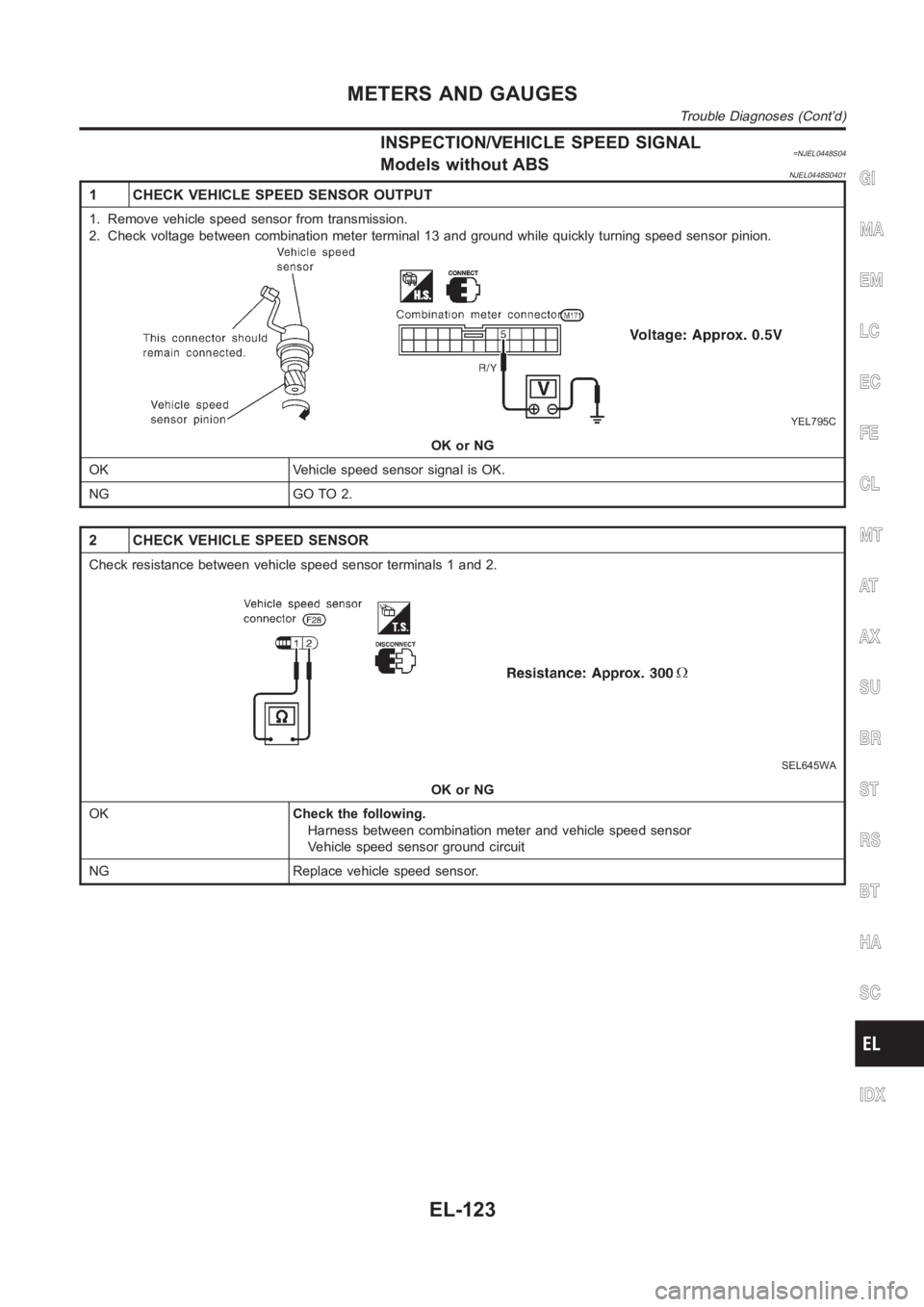
1 CHECK VEHICLE SPEED SENSOR OUTPUT
1. Remove vehicle speed sensor from transmission.
2. Check voltage between combination meter terminal 13 and ground while quickly turning speed sensor pinion.
YEL795C
OK or NG
OK Vehicle speed sensor signal is OK.
NG GO TO 2.
2 CHECK VEHICLE SPEED SENSOR
Check resistance between vehicle speed sensor terminals 1 and 2.
SEL645WA
OK or NG
OKCheck the following.
Harness between combination meter and vehicle speed sensor
Vehicle speed sensor ground circuit
NG Replace vehicle speed sensor.
GI
MA
EM
LC
EC
FE
CL
MT
AT
AX
SU
BR
ST
RS
BT
HA
SC
IDX
METERS AND GAUGES
Trouble Diagnoses (Cont’d)
EL-123
Page 2460 of 3189
Models with ABS=NJEL0448S0402
1 ABS ACTUATOR AND ELECTRIC UNIT SYSTEM INSPECTION
Perform ABS actuator and electric unit self-diagnosis.
Refer to BR-55, “CONSULT-II Functions”.
OK or NG
OK GO TO 2.
NG Check ABS control system. Refer to BR-62, “TROUBLE DIAGNOSIS — BASIC INSPEC-
TION”.
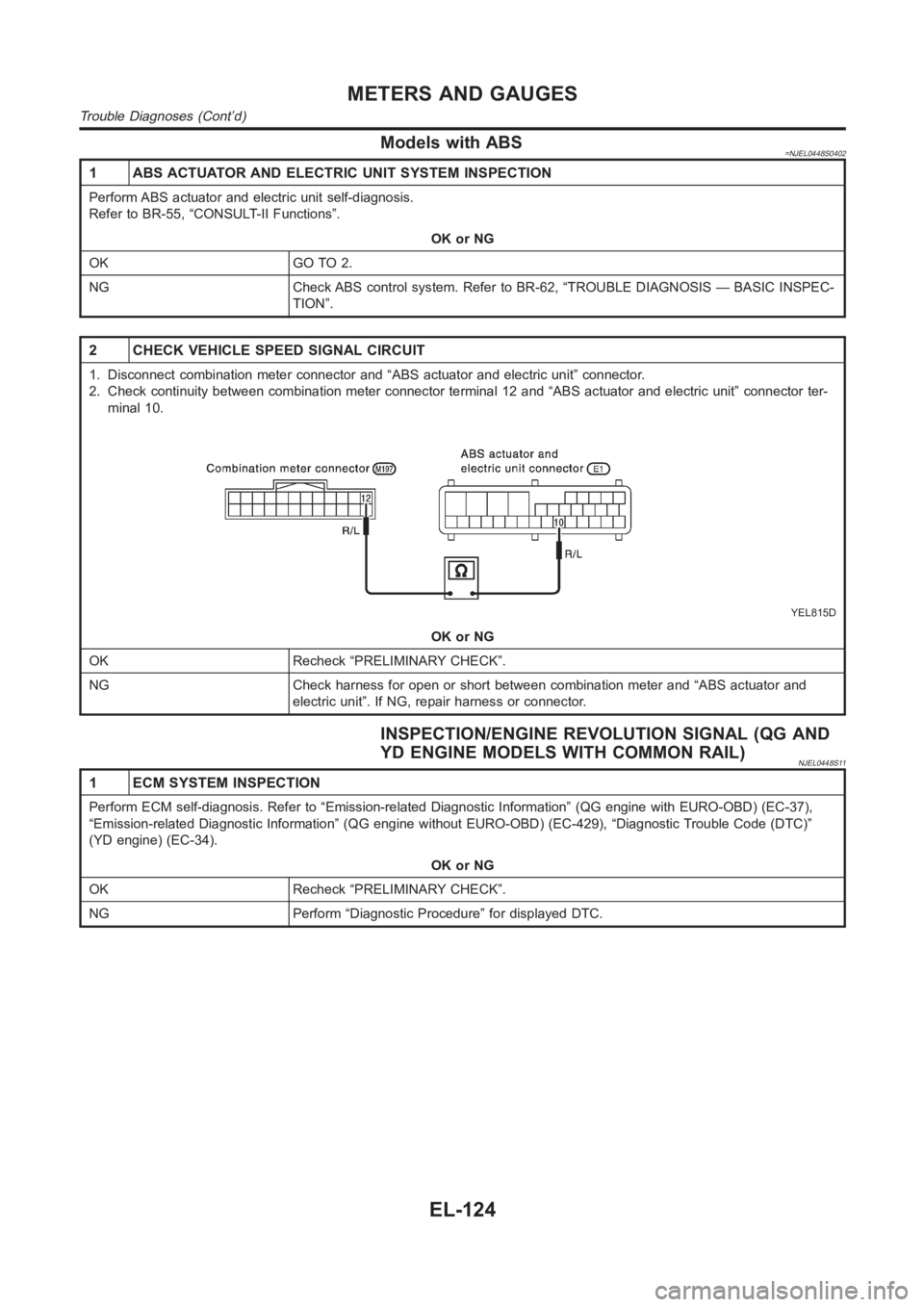
2 CHECK VEHICLE SPEED SIGNAL CIRCUIT
1. Disconnect combination meter connector and “ABS actuator and electricunit” connector.
2. Check continuity between combination meter connector terminal 12 and “ABS actuator and electric unit” connector ter-
minal 10.
YEL815D
OK or NG
OK Recheck “PRELIMINARY CHECK”.
NG Check harness for open or short between combination meter and “ABS actuator and
electric unit”. If NG, repair harness or connector.
INSPECTION/ENGINE REVOLUTION SIGNAL (QG AND
YD ENGINE MODELS WITH COMMON RAIL)
NJEL0448S11
1 ECM SYSTEM INSPECTION
Perform ECM self-diagnosis. Refer to “Emission-related Diagnostic Information” (QG engine with EURO-OBD) (EC-37),
“Emission-related Diagnostic Information” (QG engine without EURO-OBD) (EC-429), “Diagnostic Trouble Code (DTC)”
(YD engine) (EC-34).
OK or NG
OK Recheck “PRELIMINARY CHECK”.
NG Perform “Diagnostic Procedure” for displayed DTC.
METERS AND GAUGES
Trouble Diagnoses (Cont’d)
EL-124
Page 2461 of 3189
INSPECTION/ENGINE REVOLUTION SIGNAL (YD
ENGINE MODELS WITHOUT COMMON RAIL)
=NJEL0448S05
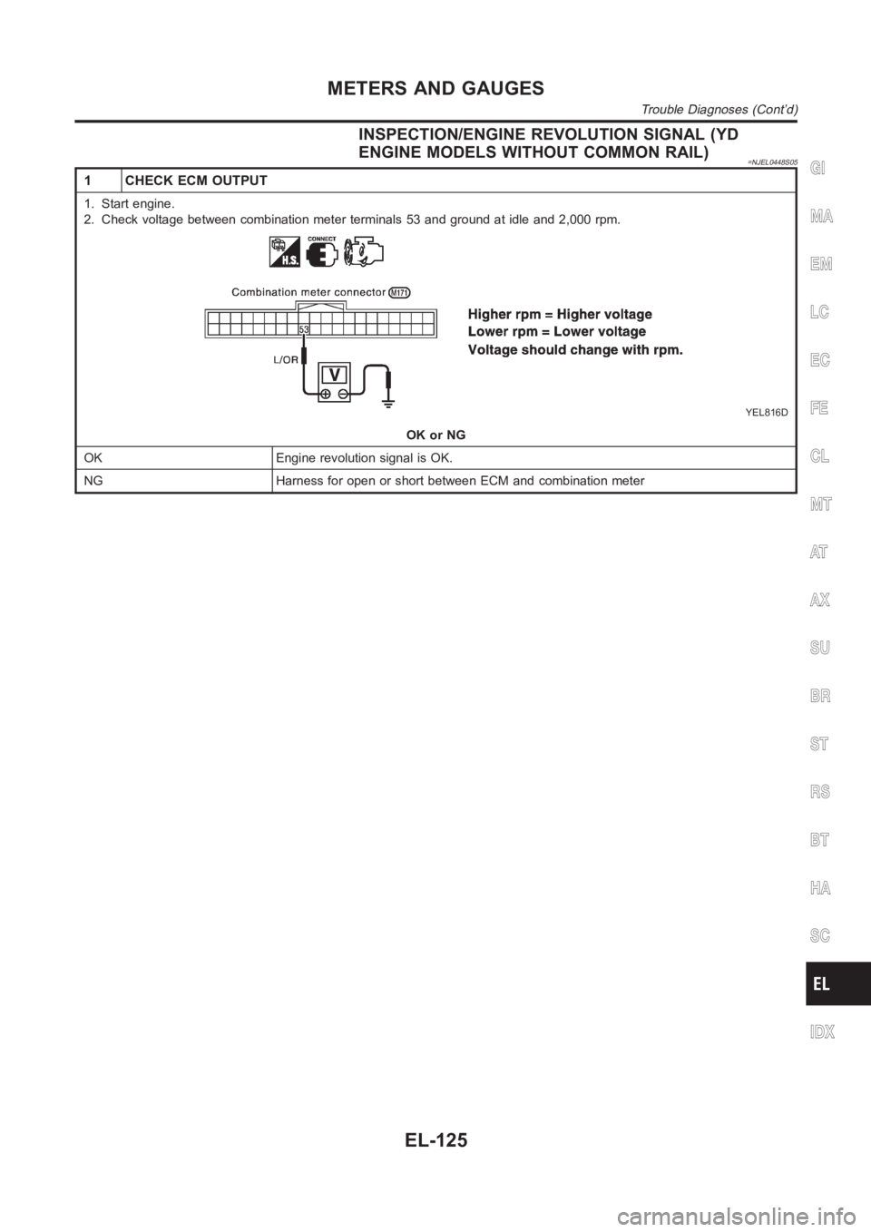
1 CHECK ECM OUTPUT
1. Start engine.
2. Check voltage between combination meter terminals 53 and ground at idleand 2,000 rpm.
YEL816D
OK or NG
OK Engine revolution signal is OK.
NG Harness for open or short between ECM and combination meter
GI
MA
EM
LC
EC
FE
CL
MT
AT
AX
SU
BR
ST
RS
BT
HA
SC
IDX
METERS AND GAUGES
Trouble Diagnoses (Cont’d)
EL-125
Page 2462 of 3189
INSPECTION/FUEL LEVEL SENSOR UNIT=NJEL0448S06
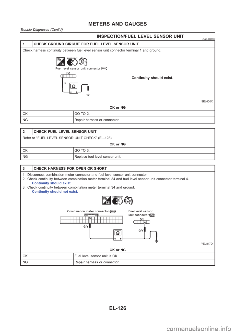
1 CHECK GROUND CIRCUIT FOR FUEL LEVEL SENSOR UNIT
Check harness continuity between fuel level sensor unit connector terminal 1 and ground.
SEL400X
OK or NG
OK GO TO 2.
NG Repair harness or connector.
2 CHECK FUEL LEVEL SENSOR UNIT
Refer to “FUEL LEVEL SENSOR UNIT CHECK” (EL-128).
OK or NG
OK GO TO 3.
NG Replace fuel level sensor unit.
3 CHECK HARNESS FOR OPEN OR SHORT
1. Disconnect combination meter connector and fuel level sensor unit connector.
2. Check continuity between combination meter terminal 34 and fuel level sensor unit connector terminal 4.
Continuity should exist.
3. Check continuity between combination meter terminal 34 and ground.
Continuity should not exist.
YEL817D
OK or NG
OK Fuel level sensor unit is OK.
NG Repair harness or connector.
METERS AND GAUGES
Trouble Diagnoses (Cont’d)
EL-126
Page 2463 of 3189
INSPECTION/THERMAL TRANSMITTER (YD ENGINE
MODELS WITHOUT COMMON RAIL)
=NJEL0448S07
1 CHECK THERMAL TRANSMITTER
Refer to “THERMAL TRANSMITTER CHECK” (EL-128).
OK or NG
OK GO TO 2.
NG Replace.
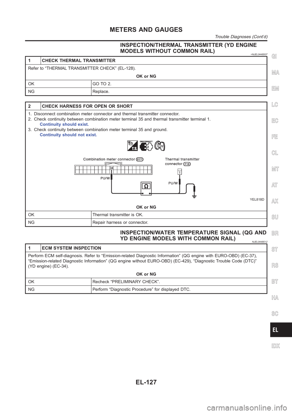
2 CHECK HARNESS FOR OPEN OR SHORT
1. Disconnect combination meter connector and thermal transmitter connector.
2. Check continuity between combination meter terminal 35 and thermal transmitter terminal 1.
Continuity should exist.
3. Check continuity between combination meter terminal 35 and ground.
Continuity should not exist.
YEL818D
OK or NG
OK Thermal transmitter is OK.
NG Repair harness or connector.
INSPECTION/WATER TEMPERATURE SIGNAL (QG AND
YD ENGINE MODELS WITH COMMON RAIL)
NJEL0448S12
1 ECM SYSTEM INSPECTION
Perform ECM self-diagnosis. Refer to “Emission-related Diagnostic Information” (QG engine with EURO-OBD) (EC-37),
“Emission-related Diagnostic Information” (QG engine without EURO-OBD) (EC-429), “Diagnostic Trouble Code (DTC)”
(YD engine) (EC-34).
OK or NG
OK Recheck “PRELIMINARY CHECK”.
NG Perform “Diagnostic Procedure” for displayed DTC.
GI
MA
EM
LC
EC
FE
CL
MT
AT
AX
SU
BR
ST
RS
BT
HA
SC
IDX
METERS AND GAUGES
Trouble Diagnoses (Cont’d)
EL-127
Page 2471 of 3189
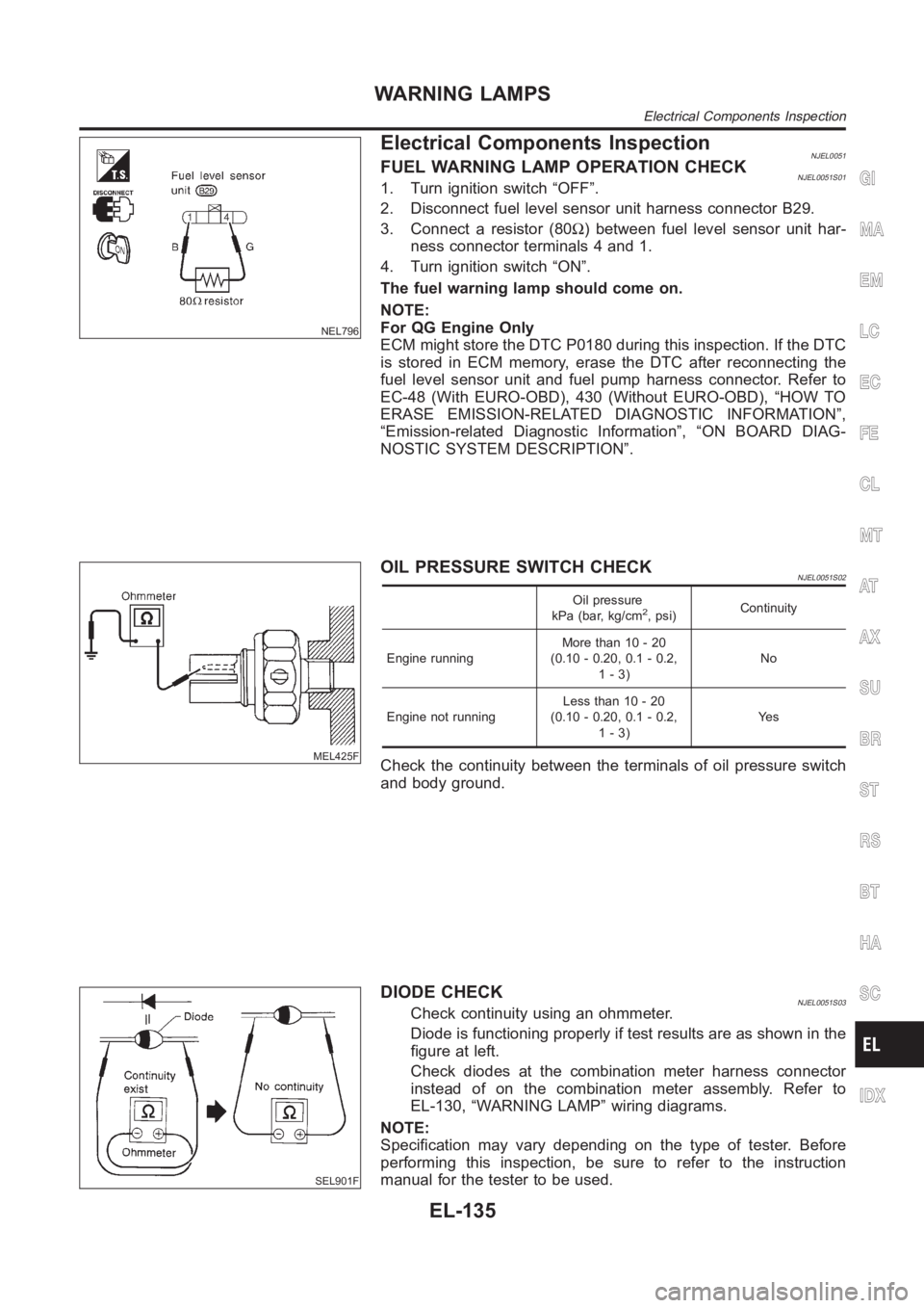
NEL796
Electrical Components InspectionNJEL0051FUEL WARNING LAMP OPERATION CHECKNJEL0051S011. Turn ignition switch “OFF”.
2. Disconnect fuel level sensor unit harness connector B29.
3. Connect a resistor (80Ω) between fuel level sensor unit har-
ness connector terminals 4 and 1.
4. Turn ignition switch “ON”.
The fuel warning lamp should come on.
NOTE:
For QG Engine Only
ECM might store the DTC P0180 during this inspection. If the DTC
is stored in ECM memory, erase the DTC after reconnecting the
fuel level sensor unit and fuel pump harness connector. Refer to
EC-48 (With EURO-OBD), 430 (Without EURO-OBD), “HOW TO
ERASE EMISSION-RELATED DIAGNOSTIC INFORMATION”,
“Emission-related Diagnostic Information”, “ON BOARD DIAG-
NOSTIC SYSTEM DESCRIPTION”.
MEL425F
OIL PRESSURE SWITCH CHECKNJEL0051S02
Oil pressure
kPa (bar, kg/cm2, psi)Continuity
Engine runningMore than 10 - 20
(0.10 - 0.20, 0.1 - 0.2,
1-3)No
Engine not runningLess than 10 - 20
(0.10 - 0.20, 0.1 - 0.2,
1-3)Ye s
Check the continuity between the terminals of oil pressure switch
and body ground.
SEL901F
DIODE CHECKNJEL0051S03Check continuity using an ohmmeter.
Diode is functioning properly if test results are as shown in the
figure at left.
Check diodes at the combination meter harness connector
instead of on the combination meter assembly. Refer to
EL-130, “WARNING LAMP” wiring diagrams.
NOTE:
Specification may vary depending on the type of tester. Before
performing this inspection, be sure to refer to the instruction
manual for the tester to be used.
GI
MA
EM
LC
EC
FE
CL
MT
AT
AX
SU
BR
ST
RS
BT
HA
SC
IDX
WARNING LAMPS
Electrical Components Inspection
EL-135
Page 2473 of 3189
from key switch terminal 2
to smart entrance control unit terminal 5.
Ground is supplied
from body grounds B9, B21 and D96 (Hatchback) or B308 (Sedan)
through front door switch (driver side) terminal 3 and 2
to smart entrance control unit terminal 43.
And, then smart entrance control unit receives any door lock signal.
LIGHT WARNING CHIMENJEL0453S02With ignition switch OFF, driver’s door open, and lighting switch in 1ST or2ND position, warning chime will
sound. Power is supplied.
from lighting switch terminal 12
through daytime light control unit terminals 11 and 10 (with daytime lightsystem)
to smart entrance control unit terminal 17
Ground is supplied
from front door switch (driver side) terminal 2
to smart entrance control unit terminal 43.
Front door switch (driver side) terminal 3 is grounded through body grounds B9, B21 and D96 (Hatchback) or
B308 (Sedan).
System Description/YD Engine Models without
Common Rail and K9K Engine Models
NJEL0550The warning chime is controlled by the time control unit.
The warning chime is located in the time control unit.
Power is supplied at all times
through 15A fuse [No. 5, located in fuse block (J/B)]
to time control unit terminal 9.
through 10A fuse [No. 12, located in the fuse block (J/B)]
to key switch terminal 1.
through 10A fuse (No. 38, located in the fuse and fusible link box)
to lighting switch terminal 11.
With the ignition switch in the ON or START position, power is supplied
through 10A fuse [No. 10, located in the fuse block (J/B)]
to time control unit terminal 1.
Ground is supplied to time control unit terminal 16 through body grounds M28 and M67.
When a signal, or combination of signals, is received by the time control unit, the warning chime will sound.
IGNITION KEY WARNING CHIMENJEL0550S01With the key in the ignition switch in the OFF position, the driver’s door open and driver’s door locked, the
warning chime will sound. Power is supplied
from key switch terminal 2
to time control unit terminal 22.
Ground is supplied
from body grounds B9, B21 and D96 (Hatchback) or B308 (Sedan)
through front door switch (driver side) terminal 3 and 2
to time control unit terminal 6, and
Ground is interrupted,
from body grounds M28 and M67
to time control unit terminal 35
LIGHT WARNING CHIMENJEL0550S02With ignition switch OFF, driver’s door open, and lighting switch in 1ST or2ND position, warning chime will
sound. Power is supplied.
from lighting switch terminal 12
to time control unit terminal 10
GI
MA
EM
LC
EC
FE
CL
MT
AT
AX
SU
BR
ST
RS
BT
HA
SC
IDX
WARNING CHIME
System Description/QG Engine Models and YD Engine Models with Common Rail(Cont’d)
EL-137