2003 NISSAN ALMERA N16 brake fluid
[x] Cancel search: brake fluidPage 1310 of 3189
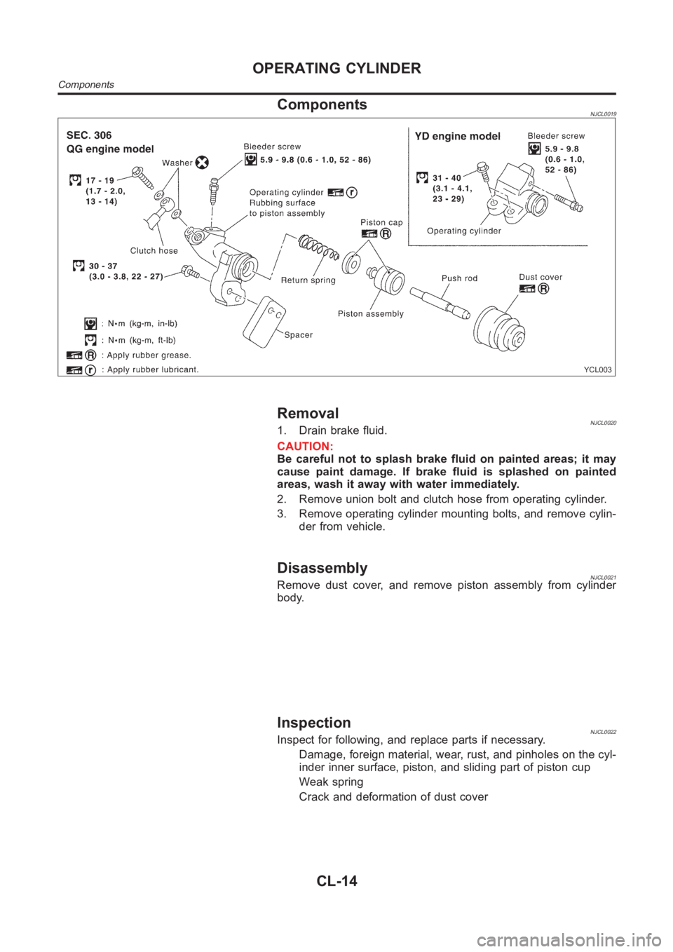
ComponentsNJCL0019
YCL003
RemovalNJCL00201. Drain brake fluid.
CAUTION:
Be careful not to splash brake fluid on painted areas; it may
cause paint damage. If brake fluid is splashed on painted
areas, wash it away with water immediately.
2. Remove union bolt and clutch hose from operating cylinder.
3. Remove operating cylinder mounting bolts, and remove cylin-
der from vehicle.
DisassemblyNJCL0021Remove dust cover, and remove piston assembly from cylinder
body.
InspectionNJCL0022Inspect for following, and replace parts if necessary.
Damage, foreign material, wear, rust, and pinholes on the cyl-
inder inner surface, piston, and sliding part of piston cup
Weak spring
Crack and deformation of dust cover
OPERATING CYLINDER
Components
CL-14
Page 1312 of 3189
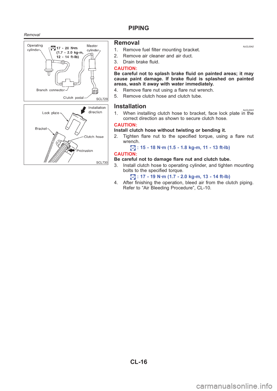
SCL729
RemovalNJCL00421. Remove fuel filter mounting bracket.
2. Remove air cleaner and air duct.
3. Drain brake fluid.
CAUTION:
Be careful not to splash brake fluid on painted areas; it may
cause paint damage. If brake fluid is splashed on painted
areas, wash it away with water immediately.
4. Remove flare nut using a flare nut wrench.
5. Remove clutch hose and clutch tube.
SCL730
InstallationNJCL00431. When installing clutch hose to bracket, face lock plate in the
correct direction as shown to secure clutch hose.
CAUTION:
Install clutch hose without twisting or bending it.
2. Tighten flare nut to the specified torque, using a flare nut
wrench.
: 15 - 18 N·m (1.5 - 1.8 kg-m, 11 - 13 ft-lb)
CAUTION:
Be careful not to damage flare nut and clutch tube.
3. Install clutch hose to operating cylinder, and tighten mounting
bolts to the specified torque.
: 17 - 19 N·m (1.7 - 2.0 kg-m, 13 - 14 ft-lb)
4. After finishing the operation, bleed air from the clutch piping.
Refer to “Air Bleeding Procedure”, CL-10.
PIPING
Removal
CL-16
Page 1458 of 3189
AT-2
Diagnostic Procedure ...........................................137
Component Inspection ..........................................138
DTC P0732 A/T 2ND GEAR FUNCTION ................139
Description ............................................................139
Wiring Diagram — AT — 2ND ..............................142
Diagnostic Procedure ...........................................143
Component Inspection ..........................................144
DTC P0733 A/T 3RD GEAR FUNCTION ................145
Description ............................................................145
Wiring Diagram — AT — 3RD ..............................148
Diagnostic Procedure ...........................................149
Component Inspection ..........................................150
DTC P0734 A/T 4TH GEAR FUNCTION ................151
Description ............................................................151
Wiring Diagram — AT — 4TH ...............................154
Diagnostic Procedure ...........................................155
Component Inspection ..........................................158
DTC P0740 TORQUE CONVERTER CLUTCH
SOLENOID VALVE .................................................159
Description ............................................................159
Wiring Diagram — AT — TCV ..............................161
Diagnostic Procedure ...........................................162
Component Inspection ..........................................163
DTC P0745 LINE PRESSURE SOLENOID VALVE .164
Description ............................................................164
Wiring Diagram — AT — LPSV ............................166
Diagnostic Procedure ...........................................167
Component Inspection ..........................................169
DTC P0750 SHIFT SOLENOID VALVE A ...............171
Description ............................................................171
Wiring Diagram — AT — SSV/A ...........................173
Diagnostic Procedure ...........................................174
Component Inspection ..........................................175
DTC P0755 SHIFT SOLENOID VALVE B ...............176
Description ............................................................176
Wiring Diagram — AT — SSV/B ...........................178
Diagnostic Procedure ...........................................179
Component Inspection ..........................................179
DTC P1705 ACCELERATOR PEDAL POSITION
(APP) SENSOR .......................................................181
Description ............................................................181
Wiring Diagram — AT — TPS ..............................184
Diagnostic Procedure ...........................................185
DTC P1760 OVERRUN CLUTCH SOLENOID
VALVE .....................................................................187
Description ............................................................187
Wiring Diagram — AT — OVRCSV ......................189
Diagnostic Procedure ...........................................190
Component Inspection ..........................................191
DTC U1000 CAN COMMUNICATION LINE ............192
Description ............................................................192
On Board Diagnosis Logic ....................................192
DTC Confirmation Procedure ...............................192
Wiring Diagram — AT ...........................................193
Diagnostic Procedure ...........................................194
DTC BATT/FLUID TEMP SEN (A/T FLUID TEMP
SENSOR CIRCUIT AND TCM POWER SOURCE) .195
Description ............................................................195
Wiring Diagram — AT — BA/FTS .........................197Diagnostic Procedure ............................................198
Component Inspection ..........................................200
DTC VEHICLE SPEED SENSOR MTR ...................201
Description ............................................................201
Wiring Diagram — AT — VSSMTR .......................203
Diagnostic Procedure ............................................204
DTC CONTROL UNIT (RAM), CONTROL UNIT
(ROM) ......................................................................205
Description ............................................................205
Diagnostic Procedure ............................................206
DTC CONTROL UNIT (EEP ROM) .........................207
Description ............................................................207
Diagnostic Procedure ............................................208
TROUBLE DIAGNOSES FOR SYMPTOMS ...........209
Wiring Diagram — AT — NONDTC ......................209
1. O/D OFF Indicator Lamp Does Not Come On ..211
2. Engine Cannot Be Started In “P” and “N” Position .212
3. In “P” Position, Vehicle Moves Forward Or Back-
ward When Pushed ...............................................213
4. In “N” Position, Vehicle Moves ..........................214
5. Large Shock. “N” → “R” Position ......................215
6. Vehicle Does Not Creep Backward In “R” Position .216
7. Vehicle Does Not Creep Forward In “D”, “2” Or
“1” Position ............................................................219
8. Vehicle Cannot Be Started From D
1 .................221
9. A/T Does Not Shift: D
1→ D2 Or Does Not Kick-
down: D
4→ D2 .....................................................223
10. A/T Does Not Shift: D
2→ D3 ..........................225
11. A/T Does Not Shift: D
3→ D4 ...........................227
12. A/T Does Not Perform Lock-up .......................230
13. A/T Does Not Hold Lock-up Condition ............231
14. Lock-up Is Not Released .................................232
15. Engine Speed Does Not Return To Idle (Light
Braking D
4→ D3 ) .................................................233
16. Vehicle Does Not Start From D
1 .....................234
17. A/T Does Not Shift: D
4→ D3 , W h e n O v e r d r i v e
Control Switch “ON” → “OFF” ...............................235
18. A/T Does Not Shift: D
3→ 22 , When Selector
Lever “D” → “2” Position .......................................235
19. A/T Does Not Shift: 2
2→ 11 , When Selector
Lever “2” → “1” Position ........................................236
20. Vehicle Does Not Decelerate By Engine Brake .237
21. TCM Self-diagnosis Does Not Activate (PNP &
Overdrive Control Switches, and Throttle Position
Sensor Circuit Checks) .........................................237
EXC.F/EURO-OBD
ON BOARD DIAGNOSTIC SYSTEM DESCRIP-
TION ........................................................................244
CONSULT-II ..........................................................244
Diagnostic Procedure Without CONSULT-II .........250
TROUBLE DIAGNOSIS — INTRODUCTION .........255
Introduction ...........................................................255
Work Flow .............................................................259
TROUBLE DIAGNOSIS — BASIC INSPECTION ...261
A/T Fluid Check ....................................................261
Stall Test ................................................................262
Page 1459 of 3189
AT-3
D
E
F
G
H
I
J
K
L
MA
B
AT Line Pressure Test ............................................... 265
Road Test ............................................................. 266
TROUBLE DIAGNOSIS — GENERAL DESCRIP-
TION ........................................................................ 283
Symptom Chart .................................................... 283
TCM Terminals and Reference Value ................... 302
CAN COMMUNICATION ........................................ 305
System Description .............................................. 305
CAN Communication Unit .................................... 305
TROUBLE DIAGNOSES FOR SYMPTOMS .......... 307
Wiring Diagram — AT — NONDTC ...................... 307
1. O/D OFF Indicator Lamp Does Not Come On . 309
2. Engine Cannot Be Started In “P” and “N” Position . 309
3. In “P” Position, Vehicle Moves Forward Or Back-
ward When Pushed .............................................. 310
4. In “N” Position, Vehicle Moves .......................... 311
5. Large Shock. “N” → “R” Position ...................... 312
6. Vehicle Does Not Creep Backward In “R” Position . 313
7. Vehicle Does Not Creep Forward In “D”, “2” Or
“1” Position ........................................................... 316
8. Vehicle Cannot Be Started From D
1 ................. 317
9. A/T Does Not Shift: D
1→ D2 Or Does Not Kick
down: D
4→ D2 ..................................................... 320
10. A/T Does Not Shift: D
2→ D3 ......................... 322
11. A/T Does Not Shift: D
3→ D4 .......................... 324
12. A/T Does Not Perform Lock-up ...................... 326
13. A/T Does Not Hold Lock-up Condition ........... 326
14. Lock-up Is Not Released ................................ 328
15. Engine Speed Does Not Return To Idle (Light
Braking D
4→ D3 ) ................................................ 328
16. Vehicle Does Not Start From D
1 ..................... 330
17. A/T Does Not Shift: D
4→ D3 , When Overdrive
Control Switch “ON” → “OFF” .............................. 330
18. A/T Does Not Shift: D
3→ 22 , When Selector
Lever “D” → “2” Position ...................................... 331
19. A/T Does Not Shift: 2
2→ 11 , When Selector
Lever “2” → “1” Position ....................................... 332
20. Vehicle Does Not Decelerate By Engine Brake . 333
21. TCM Self-diagnosis Does Not Activate (PNP &
Overdrive Control Switches, and Throttle Position
Sensor Circuit Checks) ........................................ 333
ALL
MAIN POWER SUPPLY AND GROUND CIRCUIT . 340
Wiring Diagram — AT — MAIN ............................ 340
Diagnostic Procedure ........................................... 341
VEHICLE SPEED SENSOR - A/T (REVOLUTION
SENSOR) ................................................................ 343
Description ........................................................... 343
Wiring Diagram — AT — VSSAT ......................... 345
Diagnostic Procedure ........................................... 346
DTC VEHICLE SPEED SENSOR MTR .................. 348
Description ........................................................... 348
Wiring Diagram — AT — VSSMTR ...................... 350
Diagnostic Procedure ........................................... 351
ACCELE RATOR PEDAL POSITION (APP) SEN-
SOR ........................................................................ 352
Description ........................................................... 352Wiring Diagram — AT — TPS ..............................354
Diagnostic Procedure ...........................................355
SHIFT SOLENOID VALVE A ..................................357
Description ............................................................357
Wiring Diagram — AT — SSV/A ...........................359
Diagnostic Procedure ...........................................360
Component Inspection ..........................................360
SHIFT SOLENOID VALVE B ..................................362
Description ............................................................362
Wiring Diagram — AT — SSV/B ...........................364
Diagnostic Procedure ...........................................365
Component Inspection ..........................................365
OVERRUN CLUTCH SOLENOID VALVE ...............367
Description ............................................................367
Wiring Diagram — AT — OVRCSV ......................369
Diagnostic Procedure ...........................................370
Component Inspection ..........................................371
TORQUE CONVERTER CLUTCH SOLENOID
VALVE .....................................................................372
Description ............................................................372
Wiring Diagram — AT — TCV ..............................374
Diagnostic Procedure ...........................................375
Component Inspection ..........................................375
BATT/FLUID TEMP SEN (A/T FLUID TEMP SEN-
SOR CIRCUIT AND TCM POWER SOURCE) .......377
Description ............................................................377
Wiring Diagram — AT — BA/FTS .........................379
Diagnostic Procedure ...........................................380
Component Inspection ..........................................382
ENGINE SPEED SIGNAL .......................................383
Description ............................................................383
Wiring Diagram — AT — ENGSS .........................385
Diagnostic Procedure ...........................................386
LINE PRESSURE SOLENOID VALVE ...................388
Description ............................................................388
Wiring Diagram — AT — LPSV ............................390
Diagnostic Procedure ...........................................391
Component Inspection ..........................................393
CAN COMMUNICATION LINE ...............................395
Description ............................................................395
On Board Diagnosis Logic ....................................395
Self-Diagnosis Code Confirmation Procedure ......395
Wiring Diagram — AT — CAN ..............................396
Diagnostic Procedure ...........................................397
A/T SHIFT LOCK SYSTEM ....................................398
Description ............................................................398
Shift Lock System Electrical Parts Location .........398
Wiring Diagram — SHIFT — ................................399
Diagnostic Procedure ...........................................400
KEY INTERLOCK CABLE ......................................404
Components .........................................................404
Removal ...............................................................404
Installation ............................................................405
ON-VEHICLE SERVICE ..........................................406
Control Valve Assembly and Accumulators ..........406
Control Cable Adjustment .....................................408
Park/Neutral Position (PNP) Switch Adjustment ..408
Differential Side Oil Seal Replacement ................409
Revolution Sensor Replacement ..........................409
Page 1460 of 3189
AT-4
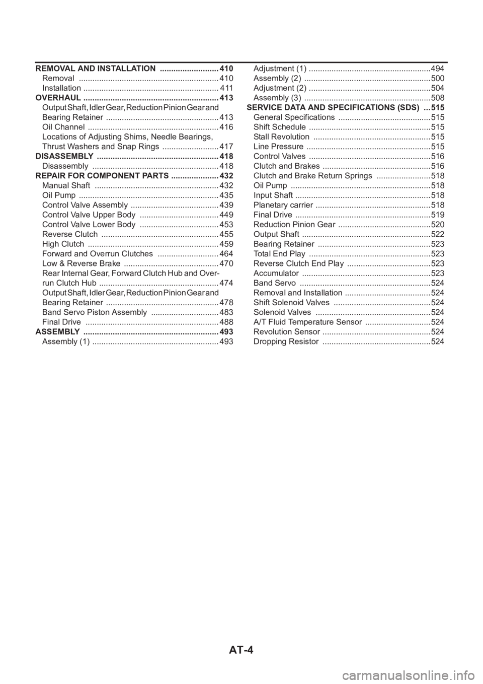
REMOVAL AND INSTALLATION ...........................410
Removal ...............................................................410
Installation .............................................................411
OVERHAUL .............................................................413
Output Shaft, Idler Gear, Reduction Pinion Gear and
Bearing Retainer ...................................................413
Oil Channel ...........................................................416
Locations of Adjusting Shims, Needle Bearings,
Thrust Washers and Snap Rings ..........................417
DISASSEMBLY .......................................................418
Disassembly .........................................................418
REPAIR FOR COMPONENT PARTS ......................432
Manual Shaft ........................................................432
Oil Pump ...............................................................435
Control Valve Assembly ........................................439
Control Valve Upper Body ....................................449
Control Valve Lower Body ....................................453
Reverse Clutch .....................................................455
High Clutch ...........................................................459
Forward and Overrun Clutches ............................464
Low & Reverse Brake ...........................................470
Rear Internal Gear, Forward Clutch Hub and Over-
run Clutch Hub ......................................................474
Output Shaft, Idler Gear, Reduction Pinion Gear and
Bearing Retainer ...................................................478
Band Servo Piston Assembly ...............................483
Final Drive ............................................................488
ASSEMBLY .............................................................493
Assembly (1) .........................................................493Adjustment (1) .......................................................494
Assembly (2) .........................................................500
Adjustment (2) .......................................................504
Assembly (3) .........................................................508
SERVICE DATA AND SPECIFICATIONS (SDS) ....515
General Specifications ......................................... .515
Shift Schedule .......................................................515
Stall Revolution .....................................................515
Line Pressure ........................................................515
Control Valves .......................................................516
Clutch and Brakes .................................................516
Clutch and Brake Return Springs .........................518
Oil Pump ......................................................
.........518
Input Shaft .............................................................518
Planetary carrier ....................................................518
Final Drive .............................................................519
Reduction Pinion Gear ..........................................520
Output Shaft ..........................................................522
Bearing Retainer ...................................................523
Total End Play .......................................................523
Reverse Clutch End Play ......................................523
Accumulator ..........................................................523
Band Servo ...........................................................524
Removal and Installation .......................................524
Shift Solenoid Valves ............................................524
Solenoid Valves ....................................................524
A/T Fluid Temperature Sensor ..............................524
Revolution Sensor .................................................524
Dropping Resistor .................................................524
Page 1469 of 3189

A/T FLUID
AT-13
D
E
F
G
H
I
J
K
L
MA
B
AT
A/T FLUIDPFP:KLE40
Checking A/T FluidECS007NC
1. Warm up engine.
2. Check for fluid leakage.
3. Before driving, fluid level can be checked at fluid temperatures
of 30 to 50°C (86 to 122°F) using “COLD” range on dipstick.
a. Park vehicle on level surface and set parking brake.
b. Start engine and move selector lever through each gear posi-
tion. Leave selector lever in “P” position.
c. Check fluid level with engine idling.
d. Remove dipstick and note reading. If level is at low side of either
range, and fluid to the charging pipe.
e. Re-insert dipstick into charging pipe as far as it will go.
f. Remove dipstick and note reading. If reading is at low side of range, add fluid to the charging pipe.
Do not overfill.
4. Drive vehicle for approximately 5 minutes in urban areas.
5. Re-check fluid level at fluid temperatures of 50 to 80°C (122 to 176°F) using “HOT” range on dipstick.
6. Check fluid condition.
●If fluid is very dark or smells burned, refer to AT section for
checking operation of A/T. Flush cooling system after repair of
A/T.
●If A/T fluid contains frictional material (clutches, bands, etc.),
replace radiator and flush cooler line using cleaning solvent
and compressed air after repair of A/T. Refer to LC-16, "Radi-
ator".
Changing A/T FluidECS007ND
1. Warm up A/T fluid.
2. Stop engine.
3. Drain A/T fluid from drain plug and refill with new A/T fluid.
Always refill same volume with drained fluid.
4. Run engine at idle speed for five minutes.
5. Check fluid level and condition. Refer to AT- 1 3 , "
Checking A/T Fluid" . If fluid is still dirty, repeat steps 2
through 5.
SMA827CA
SMA853B
Fluid grade:
Genuine Nissan ATF or equivalent. Refer to MA-
19, "RECOMMENDED FLUID AND LUBRI-
CANTS".
Fluid capacity (With torque converter):
Approx. 7.7 (6-3/4 lmp qt)
Drain plug:
: 29 - 39 N·m (3.0 - 4.0 kg-m, 22 - 29 ft-lb)
SMA027D
Page 1484 of 3189
AT-28
OVERALL SYSTEM
TCM FUNCTION
The function of the TCM is to:
●Receive input signals sent from various switches and sensors.
●Determine required line pressure, shifting point, lock-up operation, and engine brake operation.
●Send required output signals to the respective solenoid valves.
INPUT/OUTPUT SIGNAL OF TCM
Control MechanismECS007NK
LINE PRESSURE CONTROL
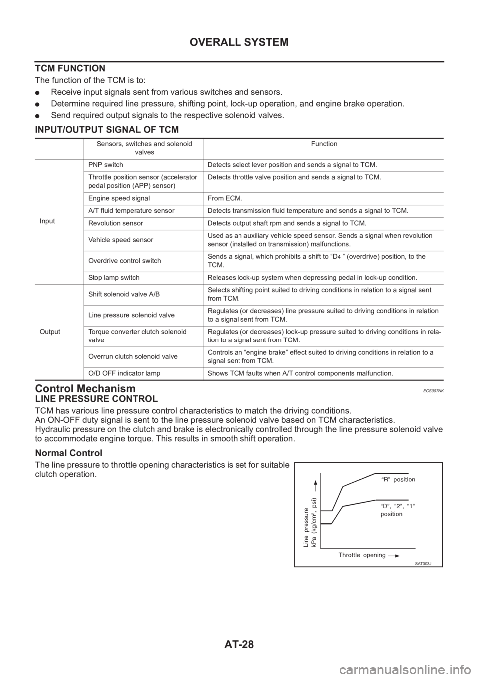
TCM has various line pressure control characteristics to match the driving conditions.
An ON-OFF duty signal is sent to the line pressure solenoid valve based on TCM characteristics.
Hydraulic pressure on the clutch and brake is electronically controlled through the line pressure solenoid valve
to accommodate engine torque. This results in smooth shift operation.
Normal Control
The line pressure to throttle opening characteristics is set for suitable
clutch operation.
Sensors, switches and solenoid
valvesFunction
InputPNP switch Detects select lever position and sends a signal to TCM.
Throttle position sensor (accelerator
pedal position (APP) sensor)Detects throttle valve position and sends a signal to TCM.
Engine speed signal From ECM.
A/T fluid temperature sensor Detects transmission fluid temperature and sends a signal to TCM.
Revolution sensor Detects output shaft rpm and sends a signal to TCM.
Vehicle speed sensorUsed as an auxiliary vehicle speed sensor. Sends a signal when revolution
sensor (installed on transmission) malfunctions.
Overdrive control switchSends a signal, which prohibits a shift to “D
4 ” (overdrive) position, to the
TCM.
Stop lamp switch Releases lock-up system when depressing pedal in lock-up condition.
OutputShift solenoid valve A/BSelects shifting point suited to driving conditions in relation to a signal sent
from TCM.
Line pressure solenoid valveRegulates (or decreases) line pressure suited to driving conditions in relation
to a signal sent from TCM.
Torque converter clutch solenoid
valveRegulates (or decreases) lock-up pressure suited to driving conditions in rela-
tion to a signal sent from TCM.
Overrun clutch solenoid valveControls an “engine brake” effect suited to driving conditions in relation to a
signal sent from TCM.
O/D OFF indicator lamp Shows TCM faults when A/T control components malfunction.
SAT003J
Page 1485 of 3189
OVERALL SYSTEM
AT-29
D
E
F
G
H
I
J
K
L
MA
B
AT
Back-up Control (Engine Brake)
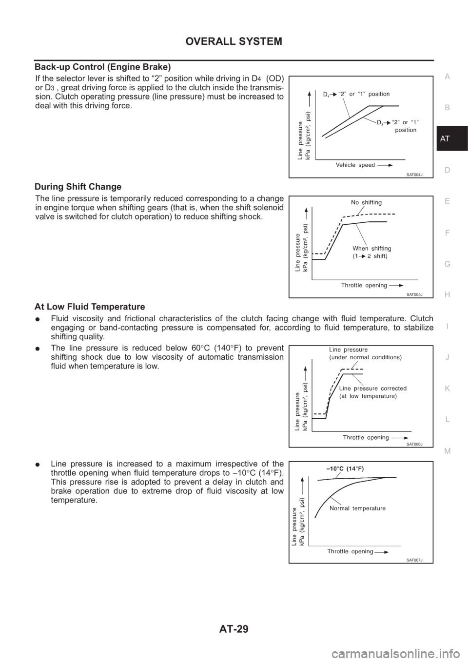
If the selector lever is shifted to “2” position while driving in D4 (OD)
or D
3 , great driving force is applied to the clutch inside the transmis-
sion. Clutch operating pressure (line pressure) must be increased to
deal with this driving force.
During Shift Change
The line pressure is temporarily reduced corresponding to a change
in engine torque when shifting gears (that is, when the shift solenoid
valve is switched for clutch operation) to reduce shifting shock.
At Low Fluid Temperature
●Fluid viscosity and frictional characteristics of the clutch facing change with fluid temperature. Clutch
engaging or band-contacting pressure is compensated for, according to fluid temperature, to stabilize
shifting quality.
●The line pressure is reduced below 60°C (140°F) to prevent
shifting shock due to low viscosity of automatic transmission
fluid when temperature is low.
●Line pressure is increased to a maximum irrespective of the
throttle opening when fluid temperature drops to −10°C (14°F).
This pressure rise is adopted to prevent a delay in clutch and
brake operation due to extreme drop of fluid viscosity at low
temperature.
SAT004J
SAT005J
SAT006J
SAT007J