2003 NISSAN ALMERA N16 brake fluid
[x] Cancel search: brake fluidPage 70 of 3189

CHASSIS AND BODY MAINTENANCE=NJMA0043S0402Abbreviations: R = Replace I = Inspect: Correct or replace if necessary
MAINTENANCE OPERATIONMAINTENANCE INTERVAL
Refer-
ence
pages Perform on a kilometer basis only.kmx1,000
(miles x 1,000)15
(9)30
(18)45
(27)60
(36)75
(45)90
(54)105
(63)120
(72)
Underhood and under vehicle
Headlamp aimingIIIIEL-44
Wheel alignment (if necessary, balance
& rotate wheels)IIIISU-6/
SU-18
Brake pads, rotors & other brake com-
ponents★IIIIBR-27
BR-28
Foot brake, parking brake & clutch (for
free play, stroke & operation)IIIIBR-12/
BR-44/
CL-9
Brake booster vacuum hoses,
connections, check valveI I BR-21
Brake & clutch, systems and fluid (for
level and leaks)IIIIBR-7
Brake fluid★R R BR-7
Power steering fluid and lines (for level
and leaks)IIIIST-7
Supplemental air bag systems See NOTE (1) RS-25
Ventilation air filter★RRRRHA-95 or
AT C - 1 2 8
Manual transaxle gear oil (check for
leakage. Use genuine NISSAN XZ
gear oil or exact equivalent)IIIIMT-14
MT-15
Automatic transaxle fluid (for level and
leaks)★IIIIAT-13
Steering gear and linkage, axle & sus-
pension parts, drive shafts, exhaust
system★IIST-7/
SU-6/
SU-18/
FE-10
NISSAN Mobility System See NOTE (2)IIIIIII —
Body corrosion See NOTE (3) BT-6
NOTE:
(1) Inspect after 10 years, then every 2 years.
(2) Check expiration date of the tyre sealant bottle. Replace if necessary.
(3) Inspect once per year.
★Maintenance items with “★” should be performed more frequently according to “Maintenance Under Severe Driving Con-
ditions”.
PERIODIC MAINTENANCE (FOR EUROPE)
Maintenance Schedule for Petrol Engines (Annual Mileage > 30,000 km/year) (Cont’d)
MA-14
Page 72 of 3189
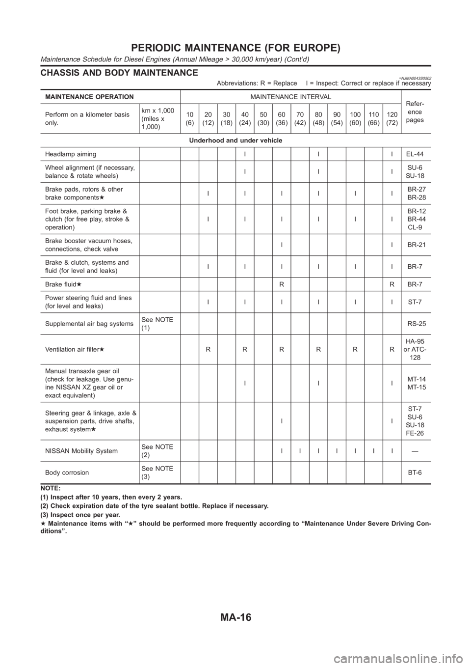
CHASSIS AND BODY MAINTENANCE=NJMA0043S0502Abbreviations: R = Replace I = Inspect: Correct or replace if necessary
MAINTENANCE OPERATIONMAINTENANCE INTERVAL
Refer-
ence
pages Perform on a kilometer basis
only.kmx1,000
(miles x
1,000)10
(6)20
(12)30
(18)40
(24)50
(30)60
(36)70
(42)80
(48)90
(54)100
(60)11 0
(66)120
(72)
Underhood and under vehicle
Headlamp aiming I I I EL-44
Wheel alignment (if necessary,
balance & rotate wheels)IIISU-6
SU-18
Brake pads, rotors & other
brake components★IIIIIIBR-27
BR-28
Foot brake, parking brake &
clutch (for free play, stroke &
operation)IIIIIIBR-12
BR-44
CL-9
Brake booster vacuum hoses,
connections, check valveI I BR-21
Brake & clutch, systems and
fluid (for level and leaks)IIIIIIBR-7
Brake fluid★R R BR-7
Power steering fluid and lines
(for level and leaks)IIIIIIST-7
Supplemental air bag systemsSee NOTE
(1)RS-25
Ventilation air filter★RRRRRRHA-95
or ATC-
128
Manual transaxle gear oil
(check for leakage. Use genu-
ine NISSAN XZ gear oil or
exact equivalent)IIIMT-14
MT-15
Steering gear & linkage, axle &
suspension parts, drive shafts,
exhaust system★IIST-7
SU-6
SU-18
FE-26
NISSAN Mobility SystemSee NOTE
(2)IIIIIII —
Body corrosionSee NOTE
(3)BT-6
NOTE:
(1) Inspect after 10 years, then every 2 years.
(2) Check expiration date of the tyre sealant bottle. Replace if necessary.
(3) Inspect once per year.
★Maintenance items with “★” should be performed more frequently according to “Maintenance Under Severe Driving Con-
ditions”.
PERIODIC MAINTENANCE (FOR EUROPE)
Maintenance Schedule for Diesel Engines (Annual Mileage > 30,000 km/year) (Cont’d)
MA-16
Page 73 of 3189
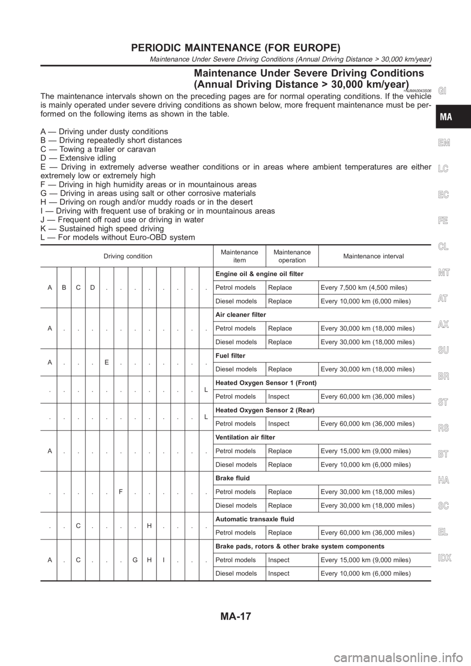
Maintenance Under Severe Driving Conditions
(Annual Driving Distance > 30,000 km/year)
=NJMA0043S06The maintenance intervals shown on the preceding pages are for normal operating conditions. If the vehicle
is mainly operated under severe driving conditions as shown below, more frequent maintenance must be per-
formed on the following items as shown in the table.
A — Driving under dusty conditions
B — Driving repeatedly short distances
C — Towing a trailer or caravan
D — Extensive idling
E — Driving in extremely adverse weather conditions or in areas where ambient temperatures are either
extremely low or extremely high
F — Driving in high humidity areas or in mountainous areas
G — Driving in areas using salt or other corrosive materials
H — Driving on rough and/or muddy roads or in the desert
I — Driving with frequent use of braking or in mountainous areas
J — Frequent off road use or driving in water
K — Sustained high speed driving
L — For models without Euro-OBD system
Driving conditionMaintenance
itemMaintenance
operationMaintenance interval
ABCD........Engine oil & engine oil filter
Petrol models Replace Every 7,500 km (4,500 miles)
Diesel models Replace Every 10,000 km (6,000 miles)
A...........Air cleaner filter
Petrol models Replace Every 30,000 km (18,000 miles)
Diesel models Replace Every 30,000 km (18,000 miles)
A...E.......Fuel filter
Diesel models Replace Every 30,000 km (18,000 miles)
...........LHeated Oxygen Sensor 1 (Front)
Petrol models Inspect Every 60,000 km (36,000 miles)
...........LHeated Oxygen Sensor 2 (Rear)
Petrol models Inspect Every 60,000 km (36,000 miles)
A...........Ventilation air filter
Petrol models Replace Every 15,000 km (9,000 miles)
Diesel models Replace Every 10,000 km (6,000 miles)
.....F......Brake fluid
Petrol models Replace Every 30,000 km (18,000 miles)
Diesel models Replace Every 30,000 km (18,000 miles)
..C....H....Automatic transaxle fluid
Petrol models Replace Every 60,000 km (36,000 miles)
A.C...GHI...Brake pads, rotors & other brake system components
Petrol models Inspect Every 15,000 km (9,000 miles)
Diesel models Inspect Every 10,000 km (6,000 miles)
GI
EM
LC
EC
FE
CL
MT
AT
AX
SU
BR
ST
RS
BT
HA
SC
EL
IDX
PERIODIC MAINTENANCE (FOR EUROPE)
Maintenance Under Severe Driving Conditions (Annual Driving Distance > 30,000 km/year)
MA-17
Page 75 of 3189
NJMA0006
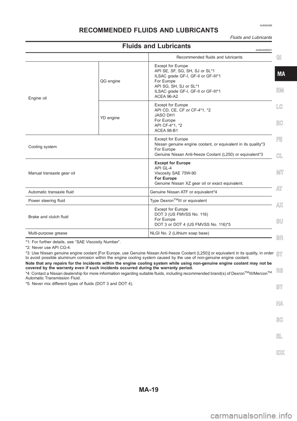
Fluids and LubricantsNJMA0006S01
Recommended fluids and lubricants
Engine oilQG engineExcept for Europe
API SE, SF, SG, SH, SJ or SL*1
ILSAC grade GF-I, GF-II or GF-III*1
For Europe
API SG, SH, SJ or SL*1
ILSAC grade GF-I, GF-II or GF-III*1
ACEA 96-A2
YD engineExcept for Europe
API CD, CE, CF or CF-4*1, *2
JASO DH1
For Europe
API CF-4*1, *2
ACEA 98-B1
Cooling systemExcept for Europe
Nissan genuine engine coolant, or equivalent in its quality*3
For Europe
Genuine Nissan Anti-freeze Coolant (L250) or equivalent*3
Manual transaxle gear oilExcept for Europe
API GL-4
Viscosity SAE 75W-90
For Europe
Genuine Nissan XZ gear oil or exact equivalent.
Automatic transaxle fluid Genuine Nissan ATF or equivalent*4
Power steering fluid Type Dexron
TMIII or equivalent
Brake and clutch fluidExcept for Europe
DOT 3 (US FMVSS No. 116)
For Europe
DOT 3 or DOT 4 (US FMVSS No. 116)*5
Multi-purpose grease NLGI No. 2 (Lithium soap base)
*1: For further details, see “SAE Viscosity Number”.
*2: Never use API CG-4.
*3: Use Nissan genuine engine coolant [For Europe, use Genuine Nissan Anti-freeze Coolant (L250)] or equivalent in its quality, in order
to avoid possible aluminum corrosion within the engine cooling system caused by the use of non-genuine engine coolant.
Note that any repairs for the incidents within the engine cooling system while using non-genuine engine coolant may not be
covered by the warranty even if such incidents occurred during the warranty period.
*4: Contact a Nissan dealership for more information regarding suitable fluids, including recommended brand(s) of Dexron
TMIII/MerconTM
Automatic Transmission Fluid.
*5: Never mix different types of fluids (DOT 3 and DOT 4).
GI
EM
LC
EC
FE
CL
MT
AT
AX
SU
BR
ST
RS
BT
HA
SC
EL
IDX
RECOMMENDED FLUIDS AND LUBRICANTS
Fluids and Lubricants
MA-19
Page 248 of 3189

crankshaft position sensor (TDC sensor) from the assem-
bly.
Always pay extra attention not to damage edge of crank-
shaft position sensor (TDC sensor) or ring gear teeth.
REMOVALNJEM0069S011. Remove engine undercover, and hood for hoisting.
2. Drain coolant from both cylinder block and radiator. Refer to
LC-43, “Changing Engine Coolant”.
3. Remove the following parts:
Battery
RH and LH front wheels
RH and LH splash covers (combined with undercover)
Auxiliary belts
Alternator
Alternator brackets
Radiator and cooling fan
Engine cover
Air ducts and air cleaner case
LH side of engine room:
4. Disconnect all harnesses and grounds that are connected to
components on vehicle.
5. Disconnect vacuum hose on vacuum pump side.
6. Disconnect fuel feed and fuel return hoses on engine side.
Immediately put blind plugs into the openings to prevent
fuel from flowing out.
7. Disconnect heater hose. Plug opening of hose to prevent cool-
ant from flowing out.
RH side of engine room:
8. Remove air conditioner compressor from brackets and move
it toward vehicle side. Secure compressor on vehicle side with
rope.
Vehicle underside:
9. Remove exhaust front tube.
10. Disconnect two hoses from power steering pump and plug to
stop fluid.
11. Remove M/T control rod and support rod.
12. Remove ABS wheel sensor, and temporarily hang brake cali-
per with rope on vehicle side.
13. Remove RH and LH drive shafts.
YEM024
14. Install engine slingers to cylinder head.
: 30 - 37 N·m (3.0 - 3.8 kg-m, 22 - 27 ft-lb)
Use engine slingers and securing bolts of the specified
service parts.
15. Lift up vehicle to appropriate level where work can be per-
formed efficiently. Using two transmission jacks, securely sup-
port engine oil pan and bottom surface of transaxle.
ENGINE ASSEMBLYYD
Removal and Installation (Cont’d)
EM-64
Page 1298 of 3189
SBR820BA
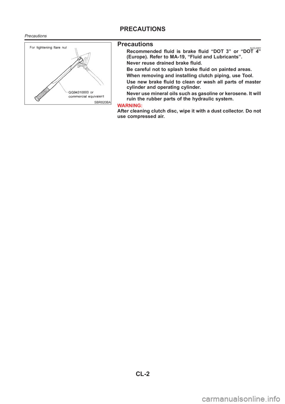
PrecautionsNJCL0001Recommended fluid is brake fluid “DOT 3” or “DOT 4”
(Europe). Refer to MA-19, “Fluid and Lubricants”.
Never reuse drained brake fluid.
Be careful not to splash brake fluid on painted areas.
When removing and installing clutch piping, use Tool.
Use new brake fluid to clean or wash all parts of master
cylinder and operating cylinder.
Never use mineral oils such as gasoline or kerosene. It will
ruin the rubber parts of the hydraulic system.
WARNING:
After cleaning clutch disc, wipe it with a dust collector. Do not
use compressed air.
PRECAUTIONS
Precautions
CL-2
Page 1306 of 3189
CLUTCH PEDAL ADJUSTMENTNJCL0006S04Pedal StrokeNJCL0006S04011. Loosen the pedal stopper bolt completely (so there is no con-
tact between pedal and stopper bolt).
2. Adjust pedal stroke to the specified value with the master cyl-
inder push rod.
3. Adjust the pedal stopper bolt until it is just in contact with the
pedal, then tighten the lock nut.
4. Once stroke is set to specification, adjust clutch pedal free
play.
Pedal stroke “S”.
Refer to “SDS”, CL-24.
Pedal Free PlayNJCL0006S04021. Adjust pedal free play to the specified value with the master
cylinder push rod.
2. Tighten lock nut of the master cylinder push rod.
Push on the clutch pedal until resistance is felt, and check the
distance the pedal moves.
Pedal free play “A”.
Refer to “SDS”, CL-24.
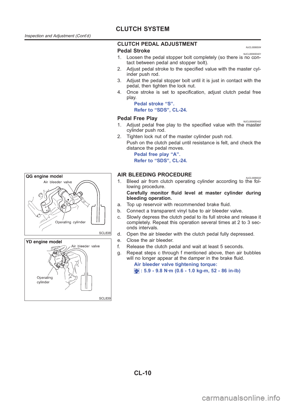
SCL838
SCL839
AIR BLEEDING PROCEDURENJCL0006S021. Bleed air from clutch operating cylinder according to the fol-
lowing procedure.
Carefully monitor fluid level at master cylinder during
bleeding operation.
a. Top up reservoir with recommended brake fluid.
b. Connect a transparent vinyl tube to air bleeder valve.
c. Slowly depress the clutch pedal to its full stroke and release it
completely. Repeat this operation several times at 2 to 3 sec-
onds intervals.
d. Open the air bleeder with the clutch pedal fully depressed.
e. Close the air bleeder.
f. Release the clutch pedal and wait at least 5 seconds.
g. Repeat steps c through f mentioned above, then air bubbles
will no longer appear at the damper in the brake fluid.
Air bleeder valve tightening torque:
: 5.9 - 9.8 N·m (0.6 - 1.0 kg-m, 52 - 86 in-lb)
CLUTCH SYSTEM
Inspection and Adjustment (Cont’d)
CL-10
Page 1308 of 3189
RemovalNJCL00081. Drain brake fluid.
CAUTION:
Be careful not to splash brake fluid on painted areas; it may
cause paint damage. If brake fluid is splashed on painted
areas, wash it away with water immediately.
2. Remove clutch tube using a flare nut wrench.
3. Remove snap pin between clutch pedal and push rod, and
remove clevis pin.
4. Unscrew master cylinder assembly mounting nuts and remove
master cylinder assembly from vehicle.
InstallationNJCL00091. Connect clutch tube to master cylinder assembly, and hand-
tighten flare nut.
2. Install master cylinder assembly to vehicle, and tighten mount-
ing nuts to the specified torque.
: 11 - 14 N·m (1.1 - 1.5 kg-m, 8 - 10 ft-lb)
3. Tighten clutch tube flare nut using a flare nut torque wrench.
: 15 - 18 N·m (1.5 - 1.8 kg-m, 11 - 13 ft-lb)
4. After installing clevis pin, install snap pin to connect clutch
pedal to push rod.
5. After finishing the operation, bleed air from clutch piping con-
nector and operating cylinder. (Refer to “Air Bleeding
Procedure”, CL-10.)
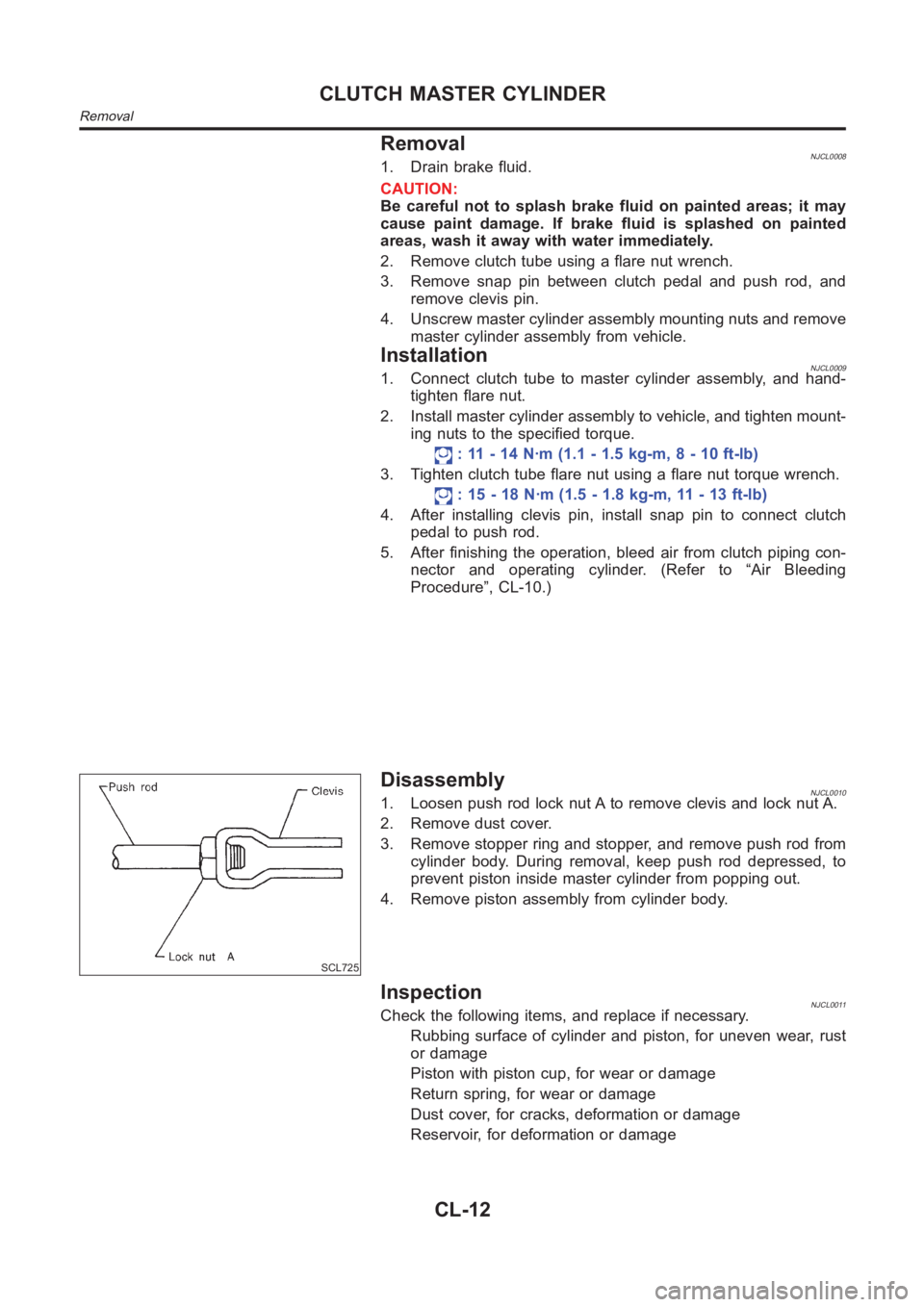
SCL725
DisassemblyNJCL00101. Loosen push rod lock nut A to remove clevis and lock nut A.
2. Remove dust cover.
3. Remove stopper ring and stopper, and remove push rod from
cylinder body. During removal, keep push rod depressed, to
prevent piston inside master cylinder from popping out.
4. Remove piston assembly from cylinder body.
InspectionNJCL0011Check the following items, and replace if necessary.
Rubbing surface of cylinder and piston, for uneven wear, rust
or damage
Piston with piston cup, for wear or damage
Return spring, for wear or damage
Dust cover, for cracks, deformation or damage
Reservoir, for deformation or damage
CLUTCH MASTER CYLINDER
Removal
CL-12