2003 NISSAN ALMERA N16 power steering pump
[x] Cancel search: power steering pumpPage 157 of 3189
![NISSAN ALMERA N16 2003 Electronic Repair Manual CYLINDER BLOCK
EM-79
[QG]
C
D
E
F
G
H
I
J
K
L
MA
EM
18. Install flywheel or drive plate.
●Install drive plate in direction shown in figure.
●Fix crankshaft with ring gear stopper (special service NISSAN ALMERA N16 2003 Electronic Repair Manual CYLINDER BLOCK
EM-79
[QG]
C
D
E
F
G
H
I
J
K
L
MA
EM
18. Install flywheel or drive plate.
●Install drive plate in direction shown in figure.
●Fix crankshaft with ring gear stopper (special service](/manual-img/5/57350/w960_57350-156.png)
CYLINDER BLOCK
EM-79
[QG]
C
D
E
F
G
H
I
J
K
L
MA
EM
18. Install flywheel or drive plate.
●Install drive plate in direction shown in figure.
●Fix crankshaft with ring gear stopper (special service tool).
●Tighten mounting bolts diagonally in several steps.
19. Install oil level gauge guide.
●Press it in with punch mark for installing instruction in direction
shown in figure.
●Apply locking agent to pressed position.
20. Install knock sensor.
●Install sensor with connector facing lower right by 45° as
shown.
CAUTION:
●If any impact by dropping is applied to the knock sensor,
replace it with new one.
●Make sure that there is no foreign material on the cylin-
der block mating surface and the back surface of the
knock sensor.
●Do not tighten the mounting bolts while holding the con-
nector.
●Make sure that the knock sensor does not interfere with other parts.
21. Install crankshaft position sensor (POS).
●Tighten bolt after fully inserting crankshaft position sensor (POS) into cylinder block.
22. Tighten accessory brackets to the following tightening torque.
23. Assemble in the reverse order of disassembly.
PBIC0595E
PBIC0596E
Power steering pump bracket:
: 16.7 - 23.5 N·m (1.7 - 2.4 kg-m, 13 - 17 ft-lb)
Alternator air conditioner compressor bracket:
: 33.3 - 46.1 N·m (3.4 - 4.7 kg-m, 25 - 34 ft-lb)
PBIC0597E
Page 172 of 3189
![NISSAN ALMERA N16 2003 Electronic Repair Manual EM-94
[QG]
SERVICE DATA AND SPECIFICATIONS (SDS)
SPARK PLUG
CYLINDER HEAD
Unit: mm (in)
VA LV E
Valve Dimensions
Unit: mm (in)
Valve Clearance
Shim Type
Unit: mm (in) Power steering oil pump 7.1 (0.28 NISSAN ALMERA N16 2003 Electronic Repair Manual EM-94
[QG]
SERVICE DATA AND SPECIFICATIONS (SDS)
SPARK PLUG
CYLINDER HEAD
Unit: mm (in)
VA LV E
Valve Dimensions
Unit: mm (in)
Valve Clearance
Shim Type
Unit: mm (in) Power steering oil pump 7.1 (0.28](/manual-img/5/57350/w960_57350-171.png)
EM-94
[QG]
SERVICE DATA AND SPECIFICATIONS (SDS)
SPARK PLUG
CYLINDER HEAD
Unit: mm (in)
VA LV E
Valve Dimensions
Unit: mm (in)
Valve Clearance
Shim Type
Unit: mm (in) Power steering oil pump 7.1 (0.280)4.4 - 4.9
(0.173 - 0.193)3.9 - 4.4
(0.154 - 0.173)
Applied pushing force 98 N (10 kg, 22 lb)Deflection adjustment
Used belt
New belt
Limit After adjustment
Make NGK Champion
Ty p eStandard LFR5A-11 REC10YC4
Hot LFR4A-11 —
Cold LFR6A-11 —
Plug gap 1.0 - 1.1 mm (0.039 - 0.043 in)
Standard Limit
Head surface distortion Less than 0.03 (0.0012) 0.1 (0.004)
Height 117.9 (4.642) —
QG15DE QG18DE
Valve head diameter “D”Intake 28.9 - 29.2 (1.138 - 1.150) 29.9 - 30.2 (1.177 - 1.189)
Exhaust 23.9 - 24.2 (0.941 - 0.953) 24.9 - 25.2 (0.980 - 0.992)
Valve length “L”Intake 92.00 - 92.50 (3.6220 - 3.6417)
Exhaust 92.37 - 92.87 (3.6366 - 3.6563)
Valve stem diameter “d”Intake 5.465 - 5.480 (0.2152 - 0.2157)
Exhaust 5.445 - 5.460 (0.2144 - 0.2150)
Valve seat angle “α”44°15′ - 44°45′
Valve margin “T” 0.8 - 0.14 (0.031 - 0.055)
Valve margin “T” limit More than 0.5 (0.020)
Valve stem end surface grinding limit 0.2 (0.008)
SEM188
For adjusting For checking
Hot Cold* (reference data) Hot
Page 205 of 3189
JEM121G
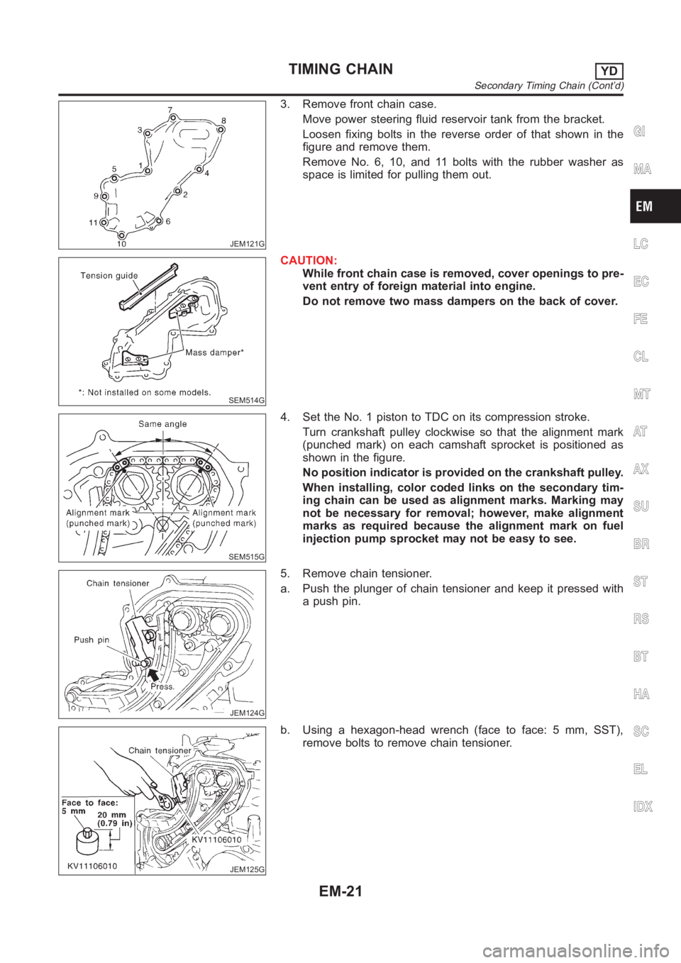
3. Remove front chain case.
Move power steering fluid reservoir tank from the bracket.
Loosen fixing bolts in the reverse order of that shown in the
figure and remove them.
Remove No. 6, 10, and 11 bolts with the rubber washer as
space is limited for pulling them out.
SEM514G
CAUTION:
While front chain case is removed, cover openings to pre-
vent entry of foreign material into engine.
Do not remove two mass dampers on the back of cover.
SEM515G
4. Set the No. 1 piston to TDC on its compression stroke.
Turn crankshaft pulley clockwise so that the alignment mark
(punched mark) on each camshaft sprocket is positioned as
shown in the figure.
No position indicator is provided on the crankshaft pulley.
When installing, color coded links on the secondary tim-
ing chain can be used as alignment marks. Marking may
not be necessary for removal; however, make alignment
marks as required because the alignment mark on fuel
injection pump sprocket may not be easy to see.
JEM124G
5. Remove chain tensioner.
a. Push the plunger of chain tensioner and keep it pressed with
a push pin.
JEM125G
b. Using a hexagon-head wrench (face to face: 5 mm, SST),
remove bolts to remove chain tensioner.
GI
MA
LC
EC
FE
CL
MT
AT
AX
SU
BR
ST
RS
BT
HA
SC
EL
IDX
TIMING CHAINYD
Secondary Timing Chain (Cont’d)
EM-21
Page 211 of 3189
JEM134G
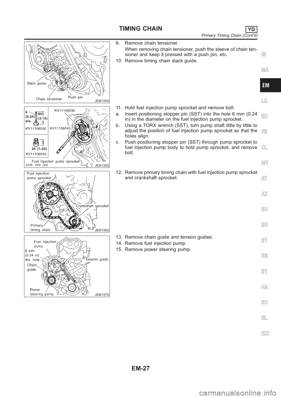
9. Remove chain tensioner.
When removing chain tensioner, push the sleeve of chain ten-
sioner and keep it pressed with a push pin, etc.
10. Remove timing chain slack guide.
JEM135G
11. Hold fuel injection pump sprocket and remove bolt.
a. Insert positioning stopper pin (SST) into the hole 6 mm (0.24
in) in the diameter on the fuel injection pump sprocket.
b. Using a TORX wrench (SST), turn pump shaft little by little to
adjust the position of fuel injection pump sprocket so that the
holes align.
c. Push positioning stopper pin (SST) through pump sprocket to
fuel injection pump body to hold pump sprocket, and remove
bolt.
JEM136G
12. Remove primary timing chain with fuel injection pump sprocket
and crankshaft sprocket.
JEM137G
13. Remove chain guide and tension guides.
14. Remove fuel injection pump.
15. Remove power steering pump.
GI
MA
LC
EC
FE
CL
MT
AT
AX
SU
BR
ST
RS
BT
HA
SC
EL
IDX
TIMING CHAINYD
Primary Timing Chain (Cont’d)
EM-27
Page 214 of 3189
JEM137G
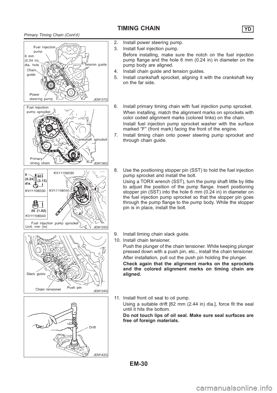
2. Install power steering pump.
3. Install fuel injection pump.
Before installing, make sure the notch on the fuel injection
pump flange and the hole 6 mm (0.24 in) in diameter on the
pump body are aligned.
4. Install chain guide and tension guides.
5. Install crankshaft sprocket, aligning it with the crankshaft key
on the far side.
JEM136G
6. Install primary timing chain with fuel injection pump sprocket.
When installing, match the alignment marks on sprockets with
color coded alignment marks (colored links) on the chain.
Install fuel injection pump sprocket washer with the surface
marked “F” (front mark) facing the front of the engine.
7. Install timing chain onto power steering pump sprocket and
through chain guide.
JEM135G
8. Use the positioning stopper pin (SST) to hold the fuel injection
pump sprocket and install the bolt.
Using a TORX wrench (SST), turn the pump shaft little by little
to adjust the position of the pump flange. Insert positioning
stopper pin (SST) into the hole 6 mm (0.24 in) in diameter on
the fuel injection pump sprocket so that the stopper pin goes
through the pump flange to the pump body. While the stopper
pin is in place, install the bolt.
JEM134G
9. Install timing chain slack guide.
10. Install chain tensioner.
Push the plunger of the chain tensioner. While keeping plunger
pressed down with a push pin, etc., install the chain tensioner.
After installation, pull out the push pin holding the plunger.
Check again that the alignment marks on the sprockets
and the colored alignment marks on timing chain are
aligned.
JEM142G
11. Install front oil seal to oil pump.
Using a suitable drift [62 mm (2.44 in) dia.], force fit the seal
until it hits the bottom.
Do not touch lips of oil seal. Make sure seal surfaces are
free of foreign materials.
TIMING CHAINYD
Primary Timing Chain (Cont’d)
EM-30
Page 215 of 3189
JEM143G
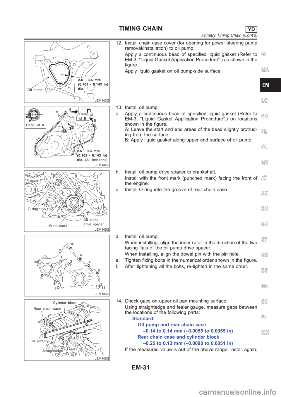
12. Install chain case cover (for opening for power steering pump
removal/installation) to oil pump.
Apply a continuous bead of specified liquid gasket (Refer to
EM-3, “Liquid Gasket Application Procedure”.) as shown in the
figure.
Apply liquid gasket on oil pump-side surface.
JEM144G
13. Install oil pump.
a. Apply a continuous bead of specified liquid gasket (Refer to
EM-3, “Liquid Gasket Application Procedure”.) on locations
shown in the figure.
A: Leave the start and end areas of the bead slightly protrud-
ing from the surface.
B: Apply liquid gasket along upper end surface of oil pump.
JEM145G
b. Install oil pump drive spacer to crankshaft.
Install with the front mark (punched mark) facing the front of
the engine.
c. Install O-ring into the groove of rear chain case.
JEM133G
d. Install oil pump.
When installing, align the inner rotor in the direction of the two
facing flats of the oil pump drive spacer.
When installing, align the dowel pin with the pin hole.
e. Tighten fixing bolts in the numerical order shown in the figure.
f. After tightening all the bolts, re-tighten in the same order.
JEM146G
14. Check gaps on upper oil pan mounting surface.
Using straightedge and feeler gauge, measure gaps between
the locations of the following parts:
Standard:
Oil pump and rear chain case
–0.14 to 0.14 mm (–0.0055 to 0.0055 in)
Rear chain case and cylinder block
–0.25 to 0.13 mm (–0.0098 to 0.0051 in)
If the measured value is out of the above range, install again.
GI
MA
LC
EC
FE
CL
MT
AT
AX
SU
BR
ST
RS
BT
HA
SC
EL
IDX
TIMING CHAINYD
Primary Timing Chain (Cont’d)
EM-31
Page 248 of 3189

crankshaft position sensor (TDC sensor) from the assem-
bly.
Always pay extra attention not to damage edge of crank-
shaft position sensor (TDC sensor) or ring gear teeth.
REMOVALNJEM0069S011. Remove engine undercover, and hood for hoisting.
2. Drain coolant from both cylinder block and radiator. Refer to
LC-43, “Changing Engine Coolant”.
3. Remove the following parts:
Battery
RH and LH front wheels
RH and LH splash covers (combined with undercover)
Auxiliary belts
Alternator
Alternator brackets
Radiator and cooling fan
Engine cover
Air ducts and air cleaner case
LH side of engine room:
4. Disconnect all harnesses and grounds that are connected to
components on vehicle.
5. Disconnect vacuum hose on vacuum pump side.
6. Disconnect fuel feed and fuel return hoses on engine side.
Immediately put blind plugs into the openings to prevent
fuel from flowing out.
7. Disconnect heater hose. Plug opening of hose to prevent cool-
ant from flowing out.
RH side of engine room:
8. Remove air conditioner compressor from brackets and move
it toward vehicle side. Secure compressor on vehicle side with
rope.
Vehicle underside:
9. Remove exhaust front tube.
10. Disconnect two hoses from power steering pump and plug to
stop fluid.
11. Remove M/T control rod and support rod.
12. Remove ABS wheel sensor, and temporarily hang brake cali-
per with rope on vehicle side.
13. Remove RH and LH drive shafts.
YEM024
14. Install engine slingers to cylinder head.
: 30 - 37 N·m (3.0 - 3.8 kg-m, 22 - 27 ft-lb)
Use engine slingers and securing bolts of the specified
service parts.
15. Lift up vehicle to appropriate level where work can be per-
formed efficiently. Using two transmission jacks, securely sup-
port engine oil pan and bottom surface of transaxle.
ENGINE ASSEMBLYYD
Removal and Installation (Cont’d)
EM-64
Page 338 of 3189
EC-8
Wiring Diagram .....................................................625
Diagnostic Procedure ...........................................626
DTC P1805 BRAKE SWITCH .................................628
Description ............................................................628
CONSULT-II Reference Value in Data Monitor Mode
.628
On Board Diagnosis Logic ....................................628
DTC Confirmation Procedure ...............................628
Wiring Diagram .....................................................629
Diagnostic Procedure ...........................................630
Component Inspection ..........................................632
HO2S1 HEATER .....................................................633
Description ............................................................633
CONSULT-II Reference Value in Data Monitor Mode
.633
Wiring Diagram .....................................................634
Diagnostic Procedure ...........................................635
Component Inspection ..........................................637
Removal and Installation ......................................637
HO2S2 HEATER .....................................................638
Description ............................................................638
CONSULT-II Reference Value in Data Monitor Mode
.638
Wiring Diagram .....................................................639
Diagnostic Procedure ...........................................640
Component Inspection ..........................................642
Removal and Installation ......................................642
IAT SENSOR ...........................................................643
Component Description ........................................643
Wiring Diagram .....................................................644
Diagnostic Procedure ...........................................645
Component Inspection ..........................................646
Removal and Installation ......................................646
HO2S1 .....................................................................647
Component Description ........................................647
CONSULT-II Reference Value in Data Monitor Mode
.647
Wiring Diagram .....................................................648
Diagnostic Procedure ...........................................649
Component Inspection ..........................................652
Removal and Installation ......................................653
HO2S2 .....................................................................654
Component Description ........................................654
CONSULT-II Reference Value in Data Monitor Mode
.654
Wiring Diagram .....................................................655
Diagnostic Procedure ...........................................656
Component Inspection ..........................................658
Removal and Installation ......................................659
IGNITION SIGNAL ..................................................660
Component Description ........................................660
Wiring Diagram .....................................................661
Diagnostic Procedure ...........................................664
Component Inspection ..........................................668
Removal and Installation ......................................669
EVAP CANISTER PURGE VOLUME CONTROL
SOLENOID VALVE .................................................670
Description ............................................................670
CONSULT-II Reference Value in Data Monitor Mode .670
Wiring Diagram .....................................................671
Diagnostic Procedure ............................................673
Component Inspection ..........................................676
Removal and Installation .......................................676
VSS ..........................................................................677
Description ............................................................677
Diagnostic Procedure ............................................677
POWER STEERING PRESSURE SENSOR ...........678
Component Description ........................................678
CONSULT-II Reference Value in Data Monitor Mode
.678
Wiring Diagram .....................................................679
Diagnostic Procedure ............................................680
Component Inspection ..........................................682
IVT CONTROL SOLENOID VALVE ........................683
Description ............................................................683
CONSULT-II Reference Value in Data Monitor Mode
.683
Wiring Diagram .....................................................685
Diagnostic Procedure ............................................686
Component Inspection ..........................................688
Removal and Installation .......................................688
PNP SWITCH ..........................................................689
Component Description ........................................689
CONSULT-II Reference Value in Data Monitor Mode
.689
Wiring Diagram .....................................................690
Diagnostic Procedure ............................................691
INJECTOR CIRCUIT ...............................................693
Component Description ........................................693
CONSULT-II Reference Value in Data Monitor Mode
.693
Wiring Diagram .....................................................694
Diagnostic Procedure ............................................695
Component Inspection ..........................................698
Removal and Installation ......................................
.698
FUEL PUMP CIRCUIT .............................................699
Description ............................................................699
CONSULT-II Reference Value in Data Monitor Mode
.699
Wiring Diagram .....................................................700
Diagnostic Procedure ............................................701
Component Inspection ..........................................703
Removal and Installation .......................................704
REFRIGERANT PRESSURE SENSOR ..................705
Component Description ........................................705
Wiring Diagram .....................................................706
Diagnostic Procedure ............................................707
Removal and Installation .......................................709
ELECTRICAL LOAD SIGNAL ................................710
Description ............................................................710
CONSULT-II Reference Value in Data Monitor Mode
.710
Wiring Diagram .....................................................711
Diagnostic Procedure ............................................712
MI & DATA LINK CONNECTORS ...........................715
Wiring Diagram—LHD Models ..............................715
Wiring Diagram—RHD Models .............................716