Page 3151 of 3189

Checking and Adjusting Drive BeltsNJST0011Refer to EM-11 (QG) or EM-11 (YD), “Checking Drive Belts”.
SMA851B
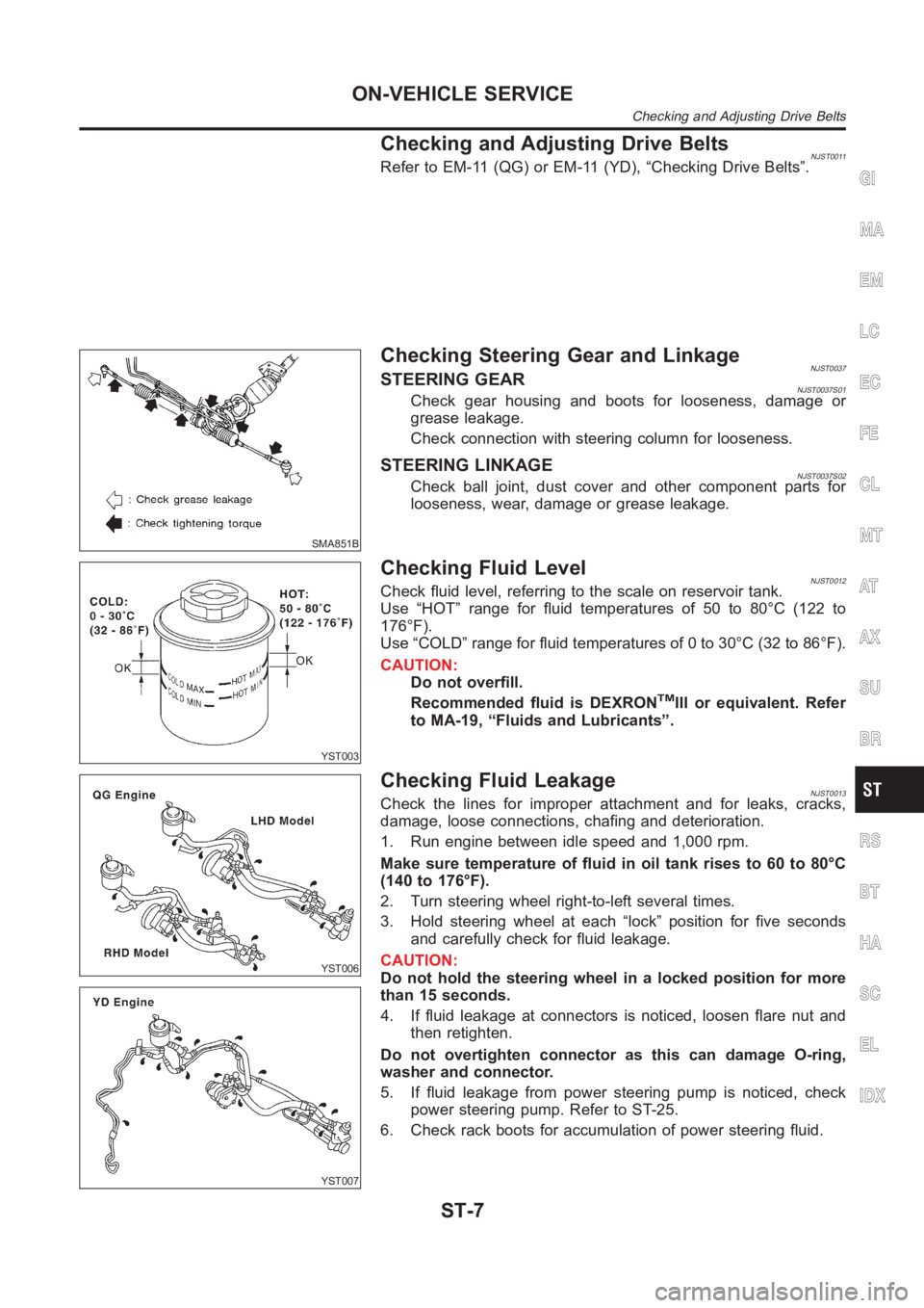
Checking Steering Gear and LinkageNJST0037STEERING GEARNJST0037S01Check gear housing and boots for looseness, damage or
grease leakage.
Check connection with steering column for looseness.
STEERING LINKAGENJST0037S02Check ball joint, dust cover and other component parts for
looseness, wear, damage or grease leakage.
YST003
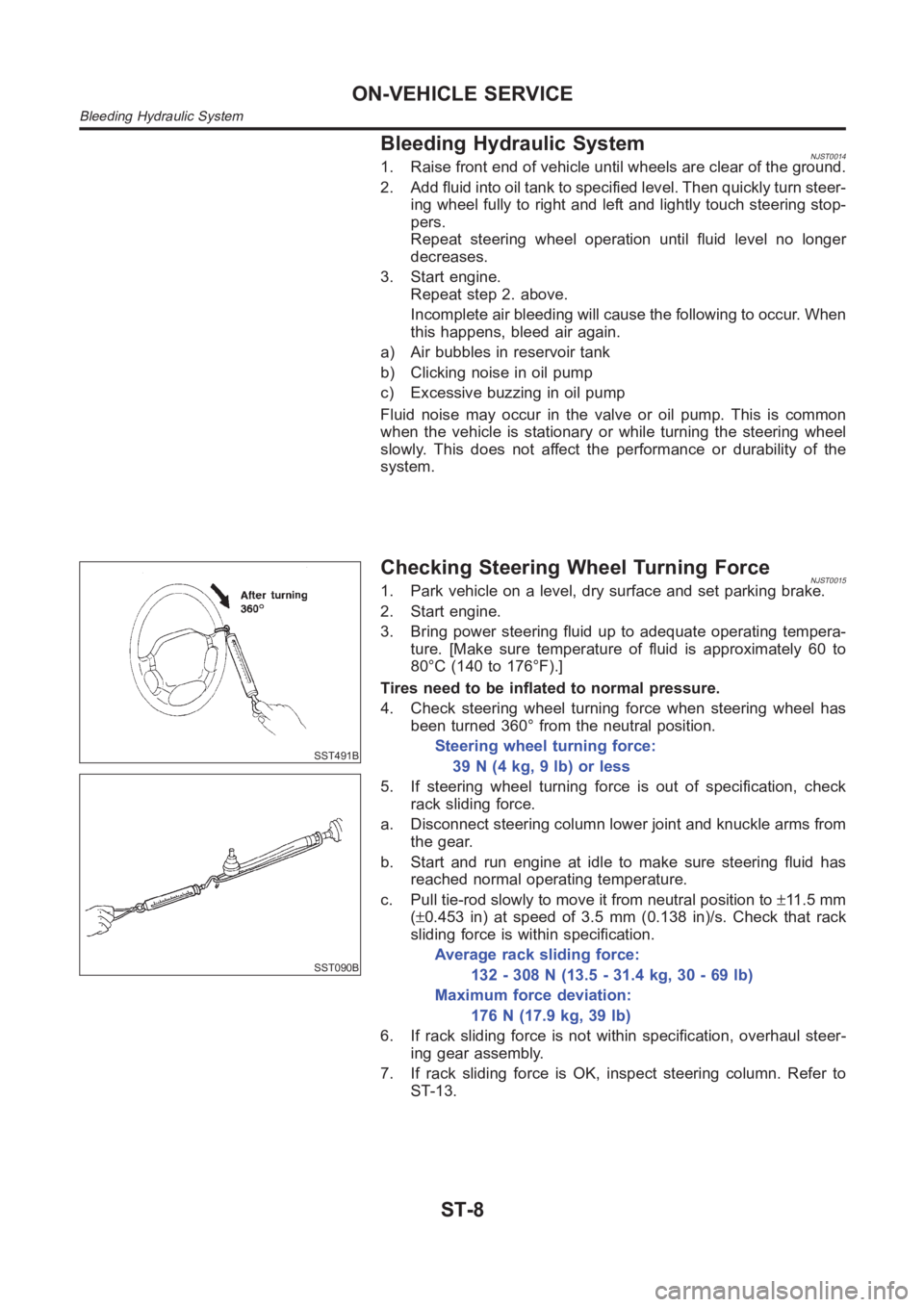
Checking Fluid LevelNJST0012Check fluid level, referring to the scale on reservoir tank.
Use “HOT” range for fluid temperatures of 50 to 80°C (122 to
176°F).
Use “COLD” range for fluid temperatures of 0 to 30°C (32 to 86°F).
CAUTION:
Do not overfill.
Recommended fluid is DEXRONTMIII or equivalent. Refer
to MA-19, “Fluids and Lubricants”.
YST006
YST007
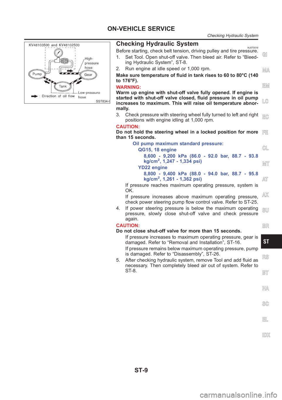
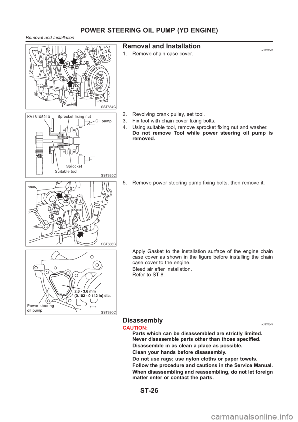
Checking Fluid LeakageNJST0013Check the lines for improper attachment and for leaks, cracks,
damage, loose connections, chafing and deterioration.
1. Run engine between idle speed and 1,000 rpm.
Make sure temperature of fluid in oil tank rises to 60 to 80°C
(140 to 176°F).
2. Turn steering wheel right-to-left several times.
3. Hold steering wheel at each “lock” position for five seconds
and carefully check for fluid leakage.
CAUTION:
Do not hold the steering wheel in a locked position for more
than 15 seconds.
4. If fluid leakage at connectors is noticed, loosen flare nut and
then retighten.
Do not overtighten connector as this can damage O-ring,
washer and connector.
5. If fluid leakage from power steering pump is noticed, check
power steering pump. Refer to ST-25.
6. Check rack boots for accumulation of power steering fluid.
GI
MA
EM
LC
EC
FE
CL
MT
AT
AX
SU
BR
RS
BT
HA
SC
EL
IDX
ON-VEHICLE SERVICE
Checking and Adjusting Drive Belts
ST-7
Page 3152 of 3189

Bleeding Hydraulic SystemNJST00141. Raise front end of vehicle until wheels are clear of the ground.
2. Add fluid into oil tank to specified level. Then quickly turn steer-
ing wheel fully to right and left and lightly touch steering stop-
pers.
Repeat steering wheel operation until fluid level no longer
decreases.
3. Start engine.
Repeat step 2. above.
Incomplete air bleeding will cause the following to occur. When
this happens, bleed air again.
a) Air bubbles in reservoir tank
b) Clicking noise in oil pump
c) Excessive buzzing in oil pump
Fluid noise may occur in the valve or oil pump. This is common
when the vehicle is stationary or while turning the steering wheel
slowly. This does not affect the performance or durability of the
system.
SST491B
SST090B
Checking Steering Wheel Turning ForceNJST00151. Park vehicle on a level, dry surface and set parking brake.
2. Start engine.
3. Bring power steering fluid up to adequate operating tempera-
ture. [Make sure temperature of fluid is approximately 60 to
80°C (140 to 176°F).]
Tires need to be inflated to normal pressure.
4. Check steering wheel turning force when steering wheel has
been turned 360° from the neutral position.
Steering wheel turning force:
39 N (4 kg, 9 lb) or less
5. If steering wheel turning force is out of specification, check
rack sliding force.
a. Disconnect steering column lower joint and knuckle arms from
the gear.
b. Start and run engine at idle to make sure steering fluid has
reached normal operating temperature.
c. Pull tie-rod slowly to move it from neutral position to±11 . 5 m m
(±0.453 in) at speed of 3.5 mm (0.138 in)/s. Check that rack
sliding force is within specification.
Average rack sliding force:
132 - 308 N (13.5 - 31.4 kg, 30 - 69 lb)
Maximum force deviation:
176 N (17.9 kg, 39 lb)
6. If rack sliding force is not within specification, overhaul steer-
ing gear assembly.
7. If rack sliding force is OK, inspect steering column. Refer to
ST-13.
ON-VEHICLE SERVICE
Bleeding Hydraulic System
ST-8
Page 3153 of 3189

SST834-I
Checking Hydraulic SystemNJST0016Before starting, check belt tension, driving pulley and tire pressure.
1. Set Tool. Open shut-off valve. Then bleed air. Refer to “Bleed-
ing Hydraulic System”, ST-8.
2. Run engine at idle speed or 1,000 rpm.
Make sure temperature of fluid in tank rises to 60 to 80°C (140
to 176°F).
WARNING:
Warm up engine with shut-off valve fully opened. If engine is
started with shut-off valve closed, fluid pressure in oil pump
increases to maximum. This will raise oil temperature abnor-
mally.
3. Check pressure with steering wheel fully turned to left and right
positions with engine idling at 1,000 rpm.
CAUTION:
Do not hold the steering wheel in a locked position for more
than 15 seconds.
Oil pump maximum standard pressure:
QG15, 18 engine
8,600 - 9,200 kPa (86.0 - 92.0 bar, 88.7 - 93.8
kg/cm
2, 1,247 - 1,334 psi)
YD22 engine
8,800 - 9,400 kPa (88.0 - 94.0 bar, 88.7 - 95.8
kg/cm
2, 1,261 - 1,362 psi)
If pressure reaches maximum operating pressure, system is
OK.
If pressure increases above maximum operating pressure,
check power steering pump flow control valve. Refer to ST-25.
4. If power steering pressure is below the maximum operating
pressure, slowly close shut-off valve and check pressure
again.
CAUTION:
Do not close shut-off valve for more than 15 seconds.
If pressure increases to maximum operating pressure, gear is
damaged. Refer to “Removal and Installation”, ST-16.
If pressure remains below maximum operating pressure, pump
is damaged. Refer to “Disassembly”, ST-26.
5. After checking hydraulic system, remove Tool and add fluid as
necessary. Then completely bleed air out of system. Refer to
ST-8.
GI
MA
EM
LC
EC
FE
CL
MT
AT
AX
SU
BR
RS
BT
HA
SC
EL
IDX
ON-VEHICLE SERVICE
Checking Hydraulic System
ST-9
Page 3168 of 3189
Component DescriptionNJST0045The power steering pump can not be disassembled on QG engine
models.
Tightening torque:
Bracket bolt:
14 - 18 N·m
(1.36 - 1.84 kg-m, 10 - 13 ft-lb)
Lower fixing bolt:
32 - 42 N·m
(3.2 - 4.2 kg-m, 24 - 31 ft-lb)
Inspection:
Check oil pump maximum pressure. Refer to “Power
Steering” in SDS.
POWER STEERING OIL PUMP (QG ENGINE)
Component Description
ST-24
Page 3169 of 3189
ComponentsNJST0038
SST882CA
1. Rear bracket
2. Rear body
3. Dowel pin
4. Side plate seal
5. Cam ring
6. Vane
7. Rotor
8. Side plate9. O-ring (Outer)
10. O-ring (Inner)
11. Front body
12. Drive shaft rear oil seal
13. Drive shaft front oil seal
14. Drive shaft
15. Snap ring
16. O-ring17. Outlet connector
18. Connector seal
19. Flow control valve
20. Flow control valve spring
21. Inlet connector
22. O-ring
23. Washer
SST883C
Pre-disassembly InspectionNJST0039Disassemble the power steering oil pump only if the following items
are found.
Oil leak from any point shown in the figure
Poor performance
GI
MA
EM
LC
EC
FE
CL
MT
AT
AX
SU
BR
RS
BT
HA
SC
EL
IDX
POWER STEERING OIL PUMP (YD ENGINE)
Components
ST-25
Page 3170 of 3189

SST884C
Removal and InstallationNJST00401. Remove chain case cover.
SST885C
2. Revolving crank pulley, set tool.
3. Fix tool with chain cover fixing bolts.
4. Using suitable tool, remove sprocket fixing nut and washer.
Do not remove Tool while power steering oil pump is
removed.
SST886C
5. Remove power steering pump fixing bolts, then remove it.
SST890C
Apply Gasket to the installation surface of the engine chain
case cover as shown in the figure before installing the chain
case cover to the engine.
Bleed air after installation.
Refer to ST-8.
DisassemblyNJST0041CAUTION:
Parts which can be disassembled are strictly limited.
Never disassemble parts other than those specified.
Disassemble in as clean a place as possible.
Clean your hands before disassembly.
Do not use rags; use nylon cloths or paper towels.
Follow the procedure and cautions in the Service Manual.
When disassembling and reassembling, do not let foreign
matter enter or contact the parts.
POWER STEERING OIL PUMP (YD ENGINE)
Removal and Installation
ST-26
Page 3171 of 3189
SST887C
Remove rear bracket and rear body.
Remove side plate seal, cam ring vane, rotor side and plate.
SST036A
Remove inlet connector and outlet connector with spring.
Be careful not to drop the flow control valve.
Do not disassemble the flow control valve.
SST888C
Remove oil seal
SST889C
Remove snap ring, then draw drive shaft.
Be careful not to drop drive shaft.
InspectionNJST0042If pulley is cracked or deformed, replace it.
If an oil leak is found around pulley shaft oil seal, replace the
seal.
If serration on pulley or pulley shaft is deformed or worn,
replace it.
GI
MA
EM
LC
EC
FE
CL
MT
AT
AX
SU
BR
RS
BT
HA
SC
EL
IDX
POWER STEERING OIL PUMP (YD ENGINE)
Disassembly (Cont’d)
ST-27
Page 3172 of 3189
SST038A
AssemblyNJST0043Assemble oil pump, noting the following instructions.
Make sure O-rings and oil seal are properly installed.
Always install new O-rings and oil seal.
Be careful of oil seal direction.
Cam ring, rotor and vanes must be replaced as a set if neces-
sary.
Coat each part with DEXRON
TMIII or equivalent when assem-
bling.
SST289A
Pay attention to the direction of rotor.
SST843A
When assembling vanes to rotor, rounded surfaces of vanes
must face cam ring side.
SST472C
Insert pin 2 into pin groove 1 of front housing and front side
plate. Then install cam ring 3 as shown at left.
Cam ring:
D
1is less than D2.
POWER STEERING OIL PUMP (YD ENGINE)
Assembly
ST-28