Page 150 of 3189
![NISSAN ALMERA N16 2003 Electronic Repair Manual EM-72
[QG]
CYLINDER BLOCK
●A commercial engine stand can be used.
NOTE:
●This example is an engine stand for holding at transaxle
mounting side with the flywheel or drive plate removed.
3](/manual-img/5/57350/w960_57350-149.png "NISSAN ALMERA N16 2003 Electronic Repair Manual EM-72
[QG]
CYLINDER BLOCK
●A commercial engine stand can be used.
NOTE:
●This example is an engine stand for holding at transaxle
mounting side with the flywheel or drive plate removed.
3")
EM-72
[QG]
CYLINDER BLOCK
●A commercial engine stand can be used.
NOTE:
●This example is an engine stand for holding at transaxle
mounting side with the flywheel or drive plate removed.
3. Drain engine oil and coolant from inside of engine.
4. Remove the following components and associated parts.
●Fuel tube and injector assembly; Refer to EM-26, "Removal and Installation" .
●Intake manifold and intake manifold collector assembly; Refer to EM-16, "Removal and Installation" .
●Ignition coil; Refer to EM-24, "Removal and Installation" .
●Rocker cover; Refer to EM-29, "Removal and Installation" .
●Oil pan and oil strainer; Refer to EM-22, "Removal and Installation" .
●Front cover and timing chain; Refer to EM-47, "Removal and Installation" .
●Camshaft; Refer to EM-32, "Removal and Installation" .
●Cylinder head assembly; Refer to EM-58, "Removal and Installation" .
●Auxiliary brackets and oil filter
5. Remove knock sensor.
CAUTION:
Avoid impacts such as a dropping.
6. Remove crankshaft position sensor (POS).
CAUTION:
●Avoid impacts such as a dropping.
●Do not disassemble.
●Keep it away from metal particles.
●Do not place sensor close to magnetic materials.
7. Remove flywheel (M/T models) or drive plate (A/T models). Fix
crankshaft with a ring gear stopper (special service tool), and
remove mounting bolts.
8. Remove rear plate.
9. Remove rear oil seal retainer.
●Insert a flat-bladed screwdriver between main bearing cap
and rear oil seal retainer to remove retainer.
10. Remove rear oil seal from rear oil seal retainer.
●Punch out with a flat-bladed screwdriver.
CAUTION:
●Be careful not to damage rear oil seal retainer.
PBIC0085E
PBIC0586E
SEM880F
Page 264 of 3189
JEM220G
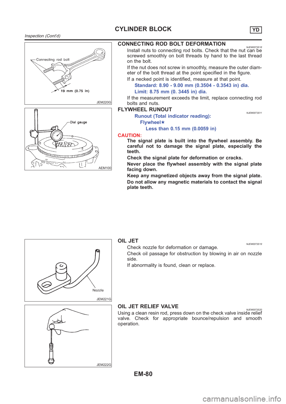
CONNECTING ROD BOLT DEFORMATIONNJEM0073S18Install nuts to connecting rod bolts. Check that the nut can be
screwed smoothly on bolt threads by hand to the last thread
on the bolt.
If the nut does not screw in smoothly, measure the outer diam-
eter of the bolt thread at the point specified in the figure.
If a necked point is identified, measure at that point.
Standard: 8.90 - 9.00 mm (0.3504 - 0.3543 in) dia.
Limit: 8.75 mm (0. 3445 in) dia.
If the measurement exceeds the limit, replace connecting rod
bolts and nuts.
AEM100
FLYWHEEL RUNOUTNJEM0073S11Runout (Total indicator reading):
Flywheel★
Less than 0.15 mm (0.0059 in)
CAUTION:
The signal plate is built into the flywheel assembly. Be
careful not to damage the signal plate, especially the
teeth.
Check the signal plate for deformation or cracks.
Never place the flywheel assembly with the signal plate
facing down.
Keep any magnetized objects away from the signal plate.
Do not allow any magnetic materials to contact the signal
plate teeth.
JEM221G
OIL JETNJEM0073S19Check nozzle for deformation or damage.
Check oil passage for obstruction by blowing in air on nozzle
side.
If abnormality is found, clean or replace.
JEM222G
OIL JET RELIEF VALVENJEM0073S20Using a clean resin rod, press down on the check valve inside relief
valve. Check for appropriate bounce/repulsion and smooth
operation.
CYLINDER BLOCKYD
Inspection (Cont’d)
EM-80
Page 592 of 3189
EC-262
[QG (WITH EURO-OBD)]
DTC P0550 PSP SENSOR
Specification data are reference values and are measured between each terminal and ground.
CAUTION:
Do not use ECM ground terminals when measuring input/output voltage. Doing so may result in dam-
age to the ECM's transistor. Use a ground other than ECM terminals, such as the ground.
Diagnostic ProcedureEBS00K95
1. RETIGHTEN GROUND SCREWS
1. Turn ignition switch “OFF”.
2. Loosen and retighten engine ground screws.
>> GO TO 2.
TER-
MINAL
NO.WIRE
COLORITEM CONDITION DATA (DC Voltage)
12 LPower steering pressure
sensor[Engine is running]
●Steering wheel is being turned.0.5 - 4.0V
[Engine is running]
●Steering wheel is not being turned.0.4 - 0.8V
57 BSensor ground
(Power steering pressure
sensor)[Engine is running]
●Idle speedApproximately 0V
65 GSensor power supply
(Power steering pressure
sensor)[Ignition switch “ON”]Approximately 5V
MBIB0095E
Page 1011 of 3189
POWER STEERING PRESSURE SENSOR
EC-681
[QG (WITHOUT EURO-OBD)]
C
D
E
F
G
H
I
J
K
L
MA
EC
3.CHECK POWER STEERING PRESSURE SENSOR OVERALL FUNCTION
Without CONSULT-II
1. Start engine.
2. Check voltage between ECM terminal 12 and ground under the
following conditions.
OK or NG
OK >>INSPECTION END
NG >> GO TO 4.
4.RETIGHTEN GROUND SCREWS
1. Turn ignition switch “OFF”.
2. Loosen and retighten engine ground screws.
>> GO TO 5.
5.CHECK PSP SENSOR POWER SUPPLY CIRCUIT
1. Disconnect PSP sensor harness connector.
2. Turn ignition switch “ON”.
3. Check voltage between PSP sensor terminal 3 and ground with
CONSULT-II or tester.
OK or NG
OK >> GO TO 6.
NG >> Repair open circuit or short to ground or short to power
in harness or connectors.
Condition Voltage
Steering wheel is being turned. 0.5 - 4.0V
Steering wheel is not being turned. 0.4 - 0.8V
MBIB0126E
MBIB0095E
MBIB0250E
Voltage: Approximately 5V
SEF509Y
Page 2142 of 3189
SFA730
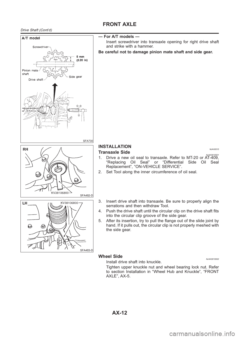
— For A/T models —
Insert screwdriver into transaxle opening for right drive shaft
and strike with a hammer.
Be careful not to damage pinion mate shaft and side gear.
SFA482-D
INSTALLATIONNJAX0015Transaxle SideNJAX0015S011. Drive a new oil seal to transaxle. Refer to MT-20 or AT-409,
“Replacing Oil Seal” or “Differential Side Oil Seal
Replacement”, “ON-VEHICLE SERVICE”.
2. Set Tool along the inner circumference of oil seal.
SFA483-D
3. Insert drive shaft into transaxle. Be sure to properly align the
serrations and then withdraw Tool.
4. Push the drive shaft until the circular clip on the drive shaft fits
into the circular clip groove of the side gear.
5. After its insertion, try to pull the flange out of the slide joint by
hand. If it pulls out, the circular clip is not properly meshed with
the side gear.
Wheel SideNJAX0015S02Install drive shaft into knuckle.
Tighten upper knuckle nut and wheel bearing lock nut. Refer
to section Installation in “Wheel Hub and Knuckle”, “FRONT
AXLE”, AX-5.
FRONT AXLE
Drive Shaft (Cont’d)
AX-12
Page 2143 of 3189
SFA476
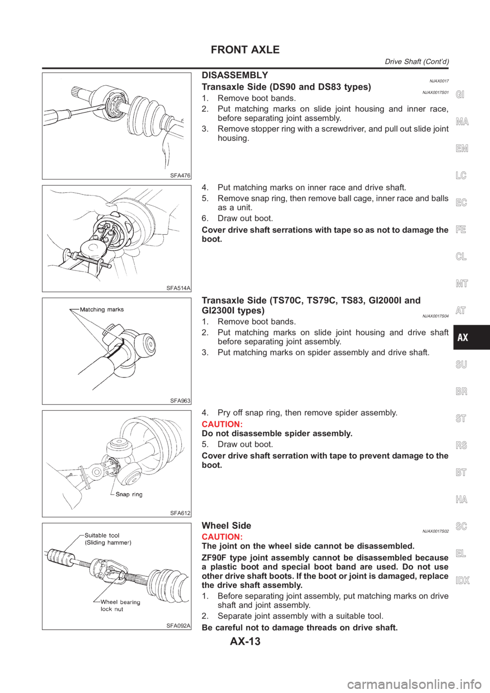
DISASSEMBLYNJAX0017Transaxle Side (DS90 and DS83 types)NJAX0017S011. Remove boot bands.
2. Put matching marks on slide joint housing and inner race,
before separating joint assembly.
3. Remove stopper ring with a screwdriver, and pull out slide joint
housing.
SFA514A
4. Put matching marks on inner race and drive shaft.
5. Remove snap ring, then remove ball cage, inner race and balls
as a unit.
6. Draw out boot.
Cover drive shaft serrations with tape so as not to damage the
boot.
SFA963
Transaxle Side (TS70C, TS79C, TS83, GI2000I and
GI2300I types)
NJAX0017S041. Remove boot bands.
2. Put matching marks on slide joint housing and drive shaft
before separating joint assembly.
3. Put matching marks on spider assembly and drive shaft.
SFA612
4. Pry off snap ring, then remove spider assembly.
CAUTION:
Do not disassemble spider assembly.
5. Draw out boot.
Cover drive shaft serration with tape to prevent damage to the
boot.
SFA092A
Wheel SideNJAX0017S02CAUTION:
The joint on the wheel side cannot be disassembled.
ZF90F type joint assembly cannot be disassembled because
a plastic boot and special boot band are used. Do not use
other drive shaft boots. If the boot or joint is damaged, replace
the drive shaft assembly.
1. Before separating joint assembly, put matching marks on drive
shaft and joint assembly.
2. Separate joint assembly with a suitable tool.
Be careful not to damage threads on drive shaft.
GI
MA
EM
LC
EC
FE
CL
MT
AT
SU
BR
ST
RS
BT
HA
SC
EL
IDX
FRONT AXLE
Drive Shaft (Cont’d)
AX-13
Page 2160 of 3189
SBR686C
Precautions
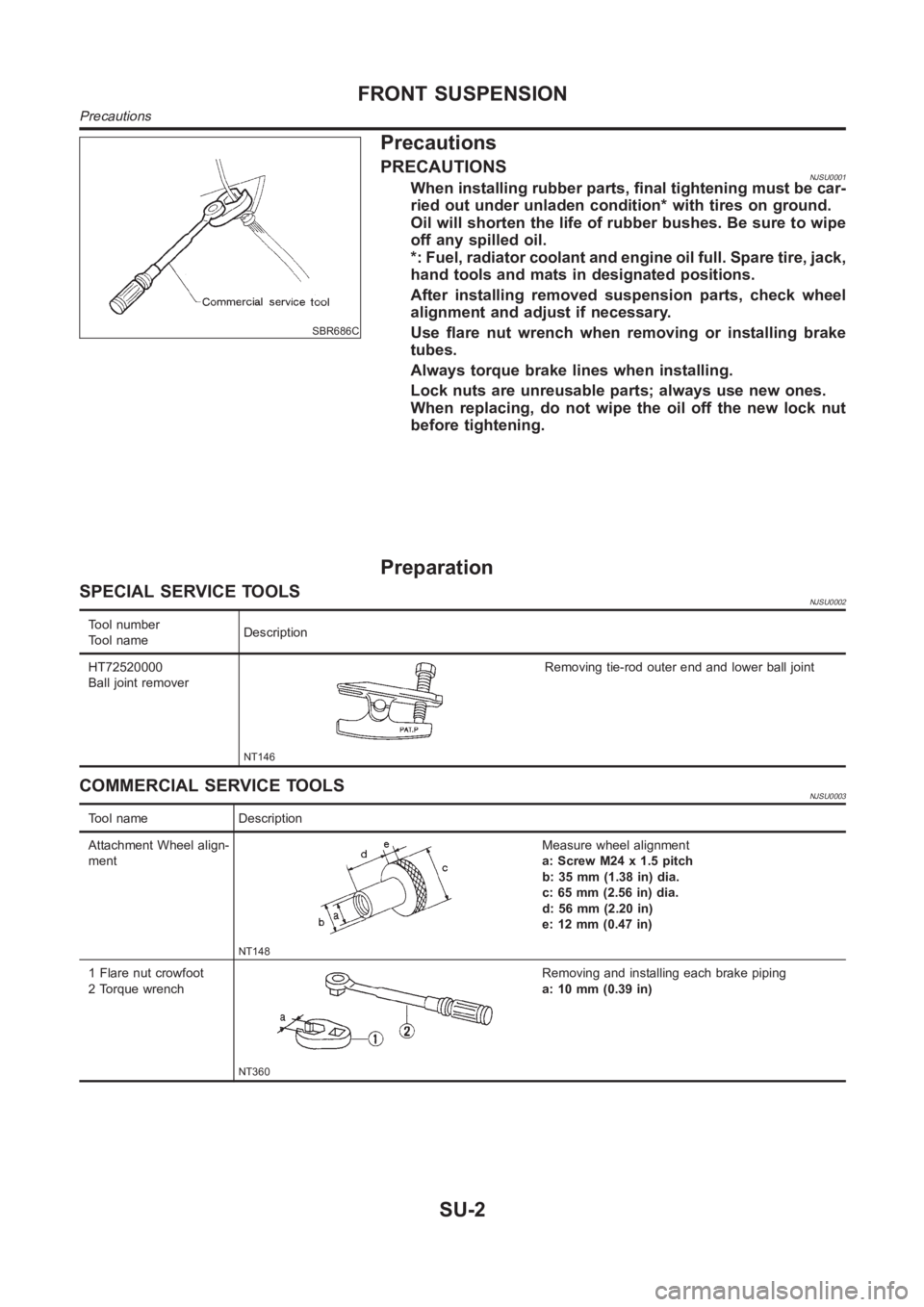
PRECAUTIONSNJSU0001When installing rubber parts, final tightening must be car-
ried out under unladen condition* with tires on ground.
Oil will shorten the life of rubber bushes. Be sure to wipe
off any spilled oil.
*: Fuel, radiator coolant and engine oil full. Spare tire, jack,
hand tools and mats in designated positions.
After installing removed suspension parts, check wheel
alignment and adjust if necessary.
Use flare nut wrench when removing or installing brake
tubes.
Always torque brake lines when installing.
Lock nuts are unreusable parts; always use new ones.
When replacing, do not wipe the oil off the new lock nut
before tightening.
Preparation
SPECIAL SERVICE TOOLSNJSU0002
Tool number
Tool nameDescription
HT72520000
Ball joint remover
NT146
Removing tie-rod outer end and lower ball joint
COMMERCIAL SERVICE TOOLSNJSU0003
Tool name Description
Attachment Wheel align-
ment
NT148
Measure wheel alignment
a: Screw M24 x 1.5 pitch
b: 35 mm (1.38 in) dia.
c: 65 mm (2.56 in) dia.
d: 56 mm (2.20 in)
e: 12 mm (0.47 in)
1 Flare nut crowfoot
2 Torque wrench
NT360
Removing and installing each brake piping
a: 10 mm (0.39 in)
FRONT SUSPENSION
Precautions
SU-2
Page 2166 of 3189
AFA050
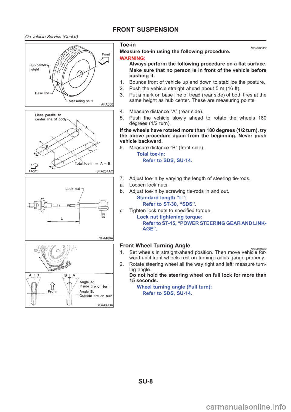
To e - i nNJSU0045S02Measure toe-in using the following procedure.
WARNING:
Always perform the following procedure on a flat surface.
Make sure that no person is in front of the vehicle before
pushing it.
1. Bounce front of vehicle up and down to stabilize the posture.
2. Push the vehicle straight ahead about 5 m (16 ft).
3. Put a mark on base line of tread (rear side) of both tires at the
same height as hub center. These are measuring points.
SFA234AC
4. Measure distance “A” (rear side).
5. Push the vehicle slowly ahead to rotate the wheels 180
degrees (1/2 turn).
If the wheels have rotated more than 180 degrees (1/2 turn), try
the above procedure again from the beginning. Never push
vehicle backward.
6. Measure distance “B” (front side).
Total toe-in:
Refer to SDS, SU-14.
SFA486A
7. Adjust toe-in by varying the length of steering tie-rods.
a. Loosen lock nuts.
b. Adjust toe-in by screwing tie-rods in and out.
Standard length “L”:
Refer to ST-30, “SDS”.
c. Tighten lock nuts to specified torque.
Lock nut tightening torque:
Refer to ST-15, “POWER STEERING GEAR AND LINK-
AGE”.
SFA439BA
Front Wheel Turning AngleNJSU0045S031. Set wheels in straight-ahead position. Then move vehicle for-
ward until front wheels rest on turning radius gauge properly.
2. Rotate steering wheel all the way right and left; measure turn-
ing angle.
Do not hold the steering wheel on full lock for more than
15 seconds.
Wheel turning angle (Full turn):
Refer to SDS, SU-14.
FRONT SUSPENSION
On-vehicle Service (Cont’d)
SU-8
![NISSAN ALMERA N16 2003 Electronic Repair Manual EC-262
[QG (WITH EURO-OBD)]
DTC P0550 PSP SENSOR
Specification data are reference values and are measured between each terminal and ground.
CAUTION:
Do not use ECM ground terminals when measuring inpu](/manual-img/5/57350/w960_57350-591.png "NISSAN ALMERA N16 2003 Electronic Repair Manual EC-262
[QG (WITH EURO-OBD)]
DTC P0550 PSP SENSOR
Specification data are reference values and are measured between each terminal and ground.
CAUTION:
Do not use ECM ground terminals when measuring inpu")
![NISSAN ALMERA N16 2003 Electronic Repair Manual POWER STEERING PRESSURE SENSOR
EC-681
[QG (WITHOUT EURO-OBD)]
C
D
E
F
G
H
I
J
K
L
MA
EC
3.CHECK POWER STEERING PRESSURE SENSOR OVERALL FUNCTION
Without CONSULT-II
1. Start engine.
2. Check voltage bet](/manual-img/5/57350/w960_57350-1010.png "NISSAN ALMERA N16 2003 Electronic Repair Manual POWER STEERING PRESSURE SENSOR
EC-681
[QG (WITHOUT EURO-OBD)]
C
D
E
F
G
H
I
J
K
L
MA
EC
3.CHECK POWER STEERING PRESSURE SENSOR OVERALL FUNCTION
Without CONSULT-II
1. Start engine.
2. Check voltage bet")