Page 609 of 3189
DTC P1122 ELECTRIC THROTTLE CONTROL FUNCTION
EC-279
[QG (WITH EURO-OBD)]
C
D
E
F
G
H
I
J
K
L
MA
EC
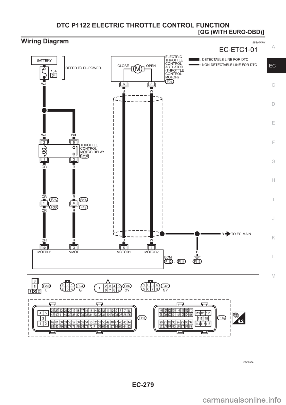
Wiring DiagramEBS00K9W
YEC297A
Page 610 of 3189
EC-280
[QG (WITH EURO-OBD)]
DTC P1122 ELECTRIC THROTTLE CONTROL FUNCTION
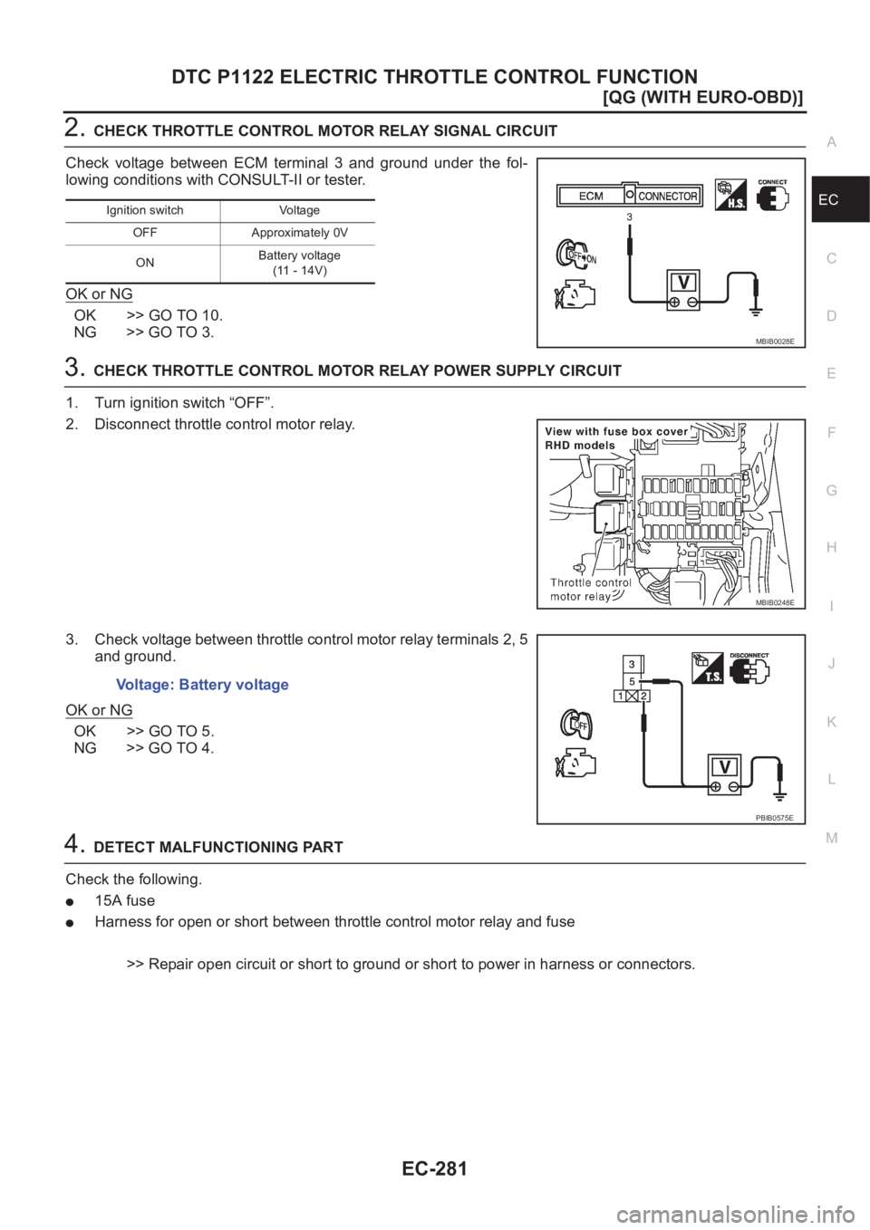
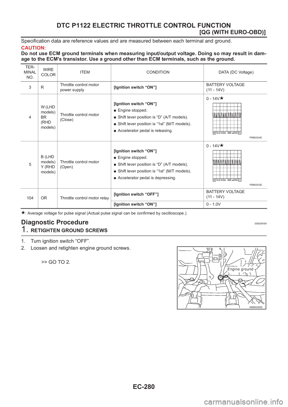
Specification data are reference values and are measured between each terminal and ground.
CAUTION:
Do not use ECM ground terminals when measuring input/output voltage. Doing so may result in dam-
age to the ECM's transistor. Use a ground other than ECM terminals, such as the ground.
: Average voltage for pulse signal (Actual pulse signal can be confirmed by oscilloscope.)
Diagnostic ProcedureEBS00K9X
1. RETIGHTEN GROUND SCREWS
1. Turn ignition switch “OFF”.
2. Loosen and retighten engine ground screws.
>> GO TO 2.
TER-
MINAL
NO.WIRE
COLORITEM CONDITION DATA (DC Voltage)
3RThrottle control motor
power supply[Ignition switch “ON”]BATTERY VOLTAGE
(11 - 14V)
4W (LHD
models)
BR
(RHD
models)Throttle control motor
(Close)[Ignition switch “ON”]
●Engine stopped.
●Shift lever position is “D” (A/T models).
●Shift lever position is “1st” (M/T models).
●Accelerator pedal is releasing.0 - 14V
5B (LHD
models)
Y (RHD
models)Throttle control motor
(Open)[Ignition switch “ON”]
●Engine stopped.
●Shift lever position is “D” (A/T models).
●Shift lever position is “1st” (M/T models).
●Accelerator pedal is depressing.0 - 14V
104 OR Throttle control motor relay[Ignition switch “OFF”]BATTERY VOLTAGE
(11 - 14V)
[Ignition switch “ON”]0 - 1.0V
PBIB0534E
PBIB0533E
MBIB0095E
Page 611 of 3189
DTC P1122 ELECTRIC THROTTLE CONTROL FUNCTION
EC-281
[QG (WITH EURO-OBD)]
C
D
E
F
G
H
I
J
K
L
MA
EC
2.CHECK THROTTLE CONTROL MOTOR RELAY SIGNAL CIRCUIT
Check voltage between ECM terminal 3 and ground under the fol-
lowing conditions with CONSULT-II or tester.
OK or NG
OK >> GO TO 10.
NG >> GO TO 3.
3.CHECK THROTTLE CONTROL MOTOR RELAY POWER SUPPLY CIRCUIT
1. Turn ignition switch “OFF”.
2. Disconnect throttle control motor relay.
3. Check voltage between throttle control motor relay terminals 2, 5
and ground.
OK or NG
OK >> GO TO 5.
NG >> GO TO 4.
4.DETECT MALFUNCTIONING PART
Check the following.
●15A fuse
●Harness for open or short between throttle control motor relay and fuse
>> Repair open circuit or short to ground or short to power in harness or connectors.
Ignition switch Voltage
OFF Approximately 0V
ONBattery voltage
(11 - 14V)
MBIB0028E
MBIB0248E
Voltage: Battery voltage
PBIB0575E
Page 612 of 3189
EC-282
[QG (WITH EURO-OBD)]
DTC P1122 ELECTRIC THROTTLE CONTROL FUNCTION
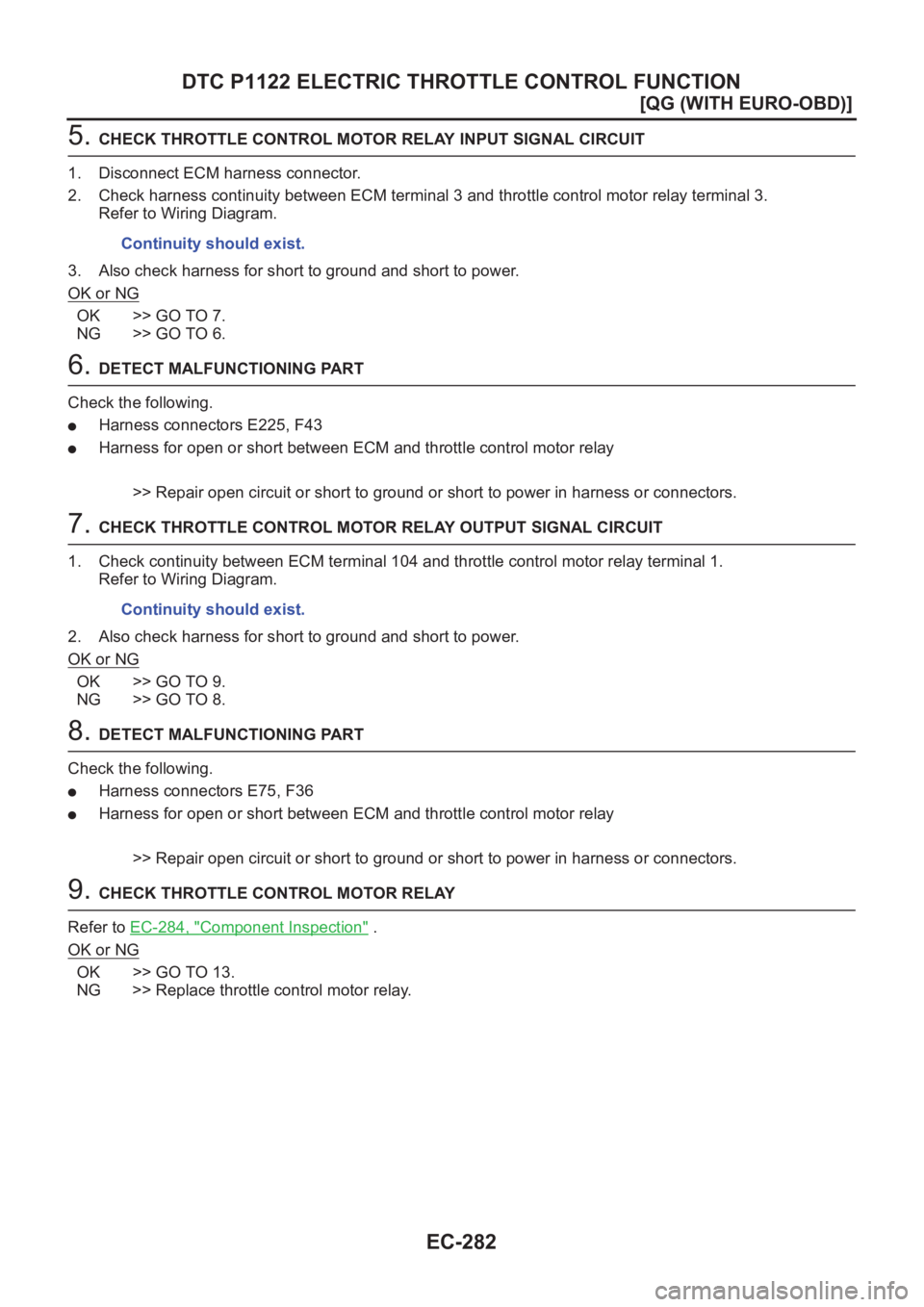
5. CHECK THROTTLE CONTROL MOTOR RELAY INPUT SIGNAL CIRCUIT
1. Disconnect ECM harness connector.
2. Check harness continuity between ECM terminal 3 and throttle control motor relay terminal 3.
Refer to Wiring Diagram.
3. Also check harness for short to ground and short to power.
OK or NG
OK >> GO TO 7.
NG >> GO TO 6.
6. DETECT MALFUNCTIONING PART
Check the following.
●Harness connectors E225, F43
●Harness for open or short between ECM and throttle control motor relay
>> Repair open circuit or short to ground or short to power in harness or connectors.
7. CHECK THROTTLE CONTROL MOTOR RELAY OUTPUT SIGNAL CIRCUIT
1. Check continuity between ECM terminal 104 and throttle control motor relay terminal 1.
Refer to Wiring Diagram.
2. Also check harness for short to ground and short to power.
OK or NG
OK >> GO TO 9.
NG >> GO TO 8.
8. DETECT MALFUNCTIONING PART
Check the following.
●Harness connectors E75, F36
●Harness for open or short between ECM and throttle control motor relay
>> Repair open circuit or short to ground or short to power in harness or connectors.
9. CHECK THROTTLE CONTROL MOTOR RELAY
Refer to EC-284, "
Component Inspection" .
OK or NG
OK >> GO TO 13.
NG >> Replace throttle control motor relay.Continuity should exist.
Continuity should exist.
Page 613 of 3189
DTC P1122 ELECTRIC THROTTLE CONTROL FUNCTION
EC-283
[QG (WITH EURO-OBD)]
C
D
E
F
G
H
I
J
K
L
MA
EC
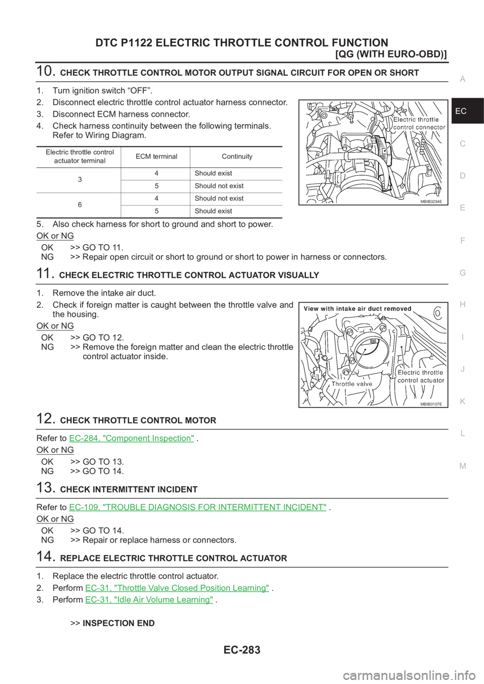
10.CHECK THROTTLE CONTROL MOTOR OUTPUT SIGNAL CIRCUIT FOR OPEN OR SHORT
1. Turn ignition switch “OFF”.
2. Disconnect electric throttle control actuator harness connector.
3. Disconnect ECM harness connector.
4. Check harness continuity between the following terminals.
Refer to Wiring Diagram.
5. Also check harness for short to ground and short to power.
OK or NG
OK >> GO TO 11.
NG >> Repair open circuit or short to ground or short to power in harness or connectors.
11 . CHECK ELECTRIC THROTTLE CONTROL ACTUATOR VISUALLY
1. Remove the intake air duct.
2. Check if foreign matter is caught between the throttle valve and
the housing.
OK or NG
OK >> GO TO 12.
NG >> Remove the foreign matter and clean the electric throttle
control actuator inside.
12.CHECK THROTTLE CONTROL MOTOR
Refer to EC-284, "
Component Inspection" .
OK or NG
OK >> GO TO 13.
NG >> GO TO 14.
13.CHECK INTERMITTENT INCIDENT
Refer to EC-109, "
TROUBLE DIAGNOSIS FOR INTERMITTENT INCIDENT" .
OK or NG
OK >> GO TO 14.
NG >> Repair or replace harness or connectors.
14.REPLACE ELECTRIC THROTTLE CONTROL ACTUATOR
1. Replace the electric throttle control actuator.
2. Perform EC-31, "
Throttle Valve Closed Position Learning" .
3. Perform EC-31, "
Idle Air Volume Learning" .
>>INSPECTION END
Electric throttle control
actuator terminalECM terminal Continuity
34 Should exist
5 Should not exist
64 Should not exist
5 Should exist
MBIB0254E
MBIB0107E
Page 614 of 3189
EC-284
[QG (WITH EURO-OBD)]
DTC P1122 ELECTRIC THROTTLE CONTROL FUNCTION
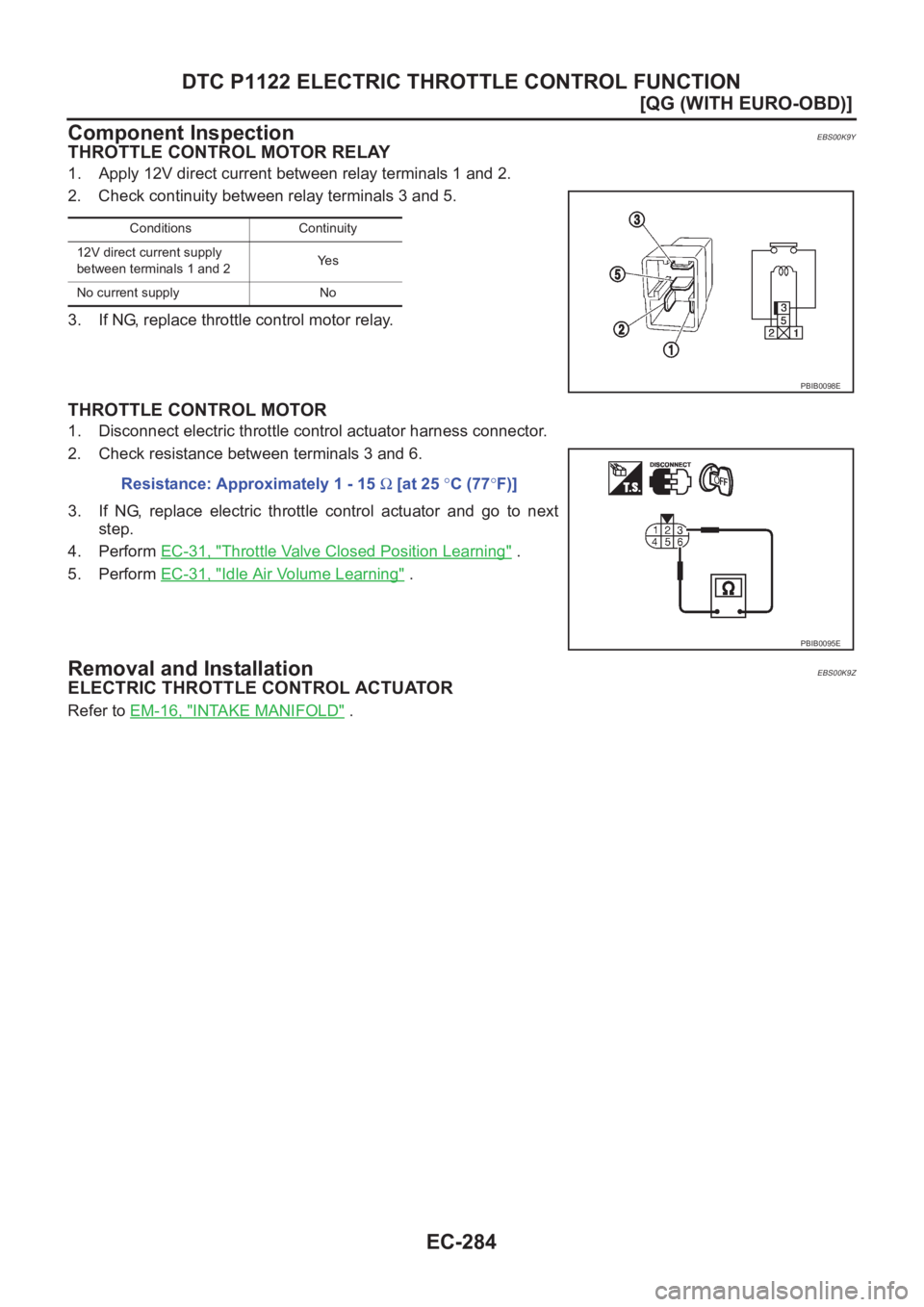
Component Inspection
EBS00K9Y
THROTTLE CONTROL MOTOR RELAY
1. Apply 12V direct current between relay terminals 1 and 2.
2. Check continuity between relay terminals 3 and 5.
3. If NG, replace throttle control motor relay.
THROTTLE CONTROL MOTOR
1. Disconnect electric throttle control actuator harness connector.
2. Check resistance between terminals 3 and 6.
3. If NG, replace electric throttle control actuator and go to next
step.
4. Perform EC-31, "
Throttle Valve Closed Position Learning" .
5. Perform EC-31, "
Idle Air Volume Learning" .
Removal and InstallationEBS00K9Z
ELECTRIC THROTTLE CONTROL ACTUATOR
Refer to EM-16, "INTAKE MANIFOLD" .
Conditions Continuity
12V direct current supply
between terminals 1 and 2Ye s
No current supply No
PBIB0098E
Resistance: Approximately 1 - 15 Ω [at 25 °C (77°F)]
PBIB0095E
Page 736 of 3189
EC-406
[QG (WITHOUT EURO-OBD)]
INDEX FOR DTC
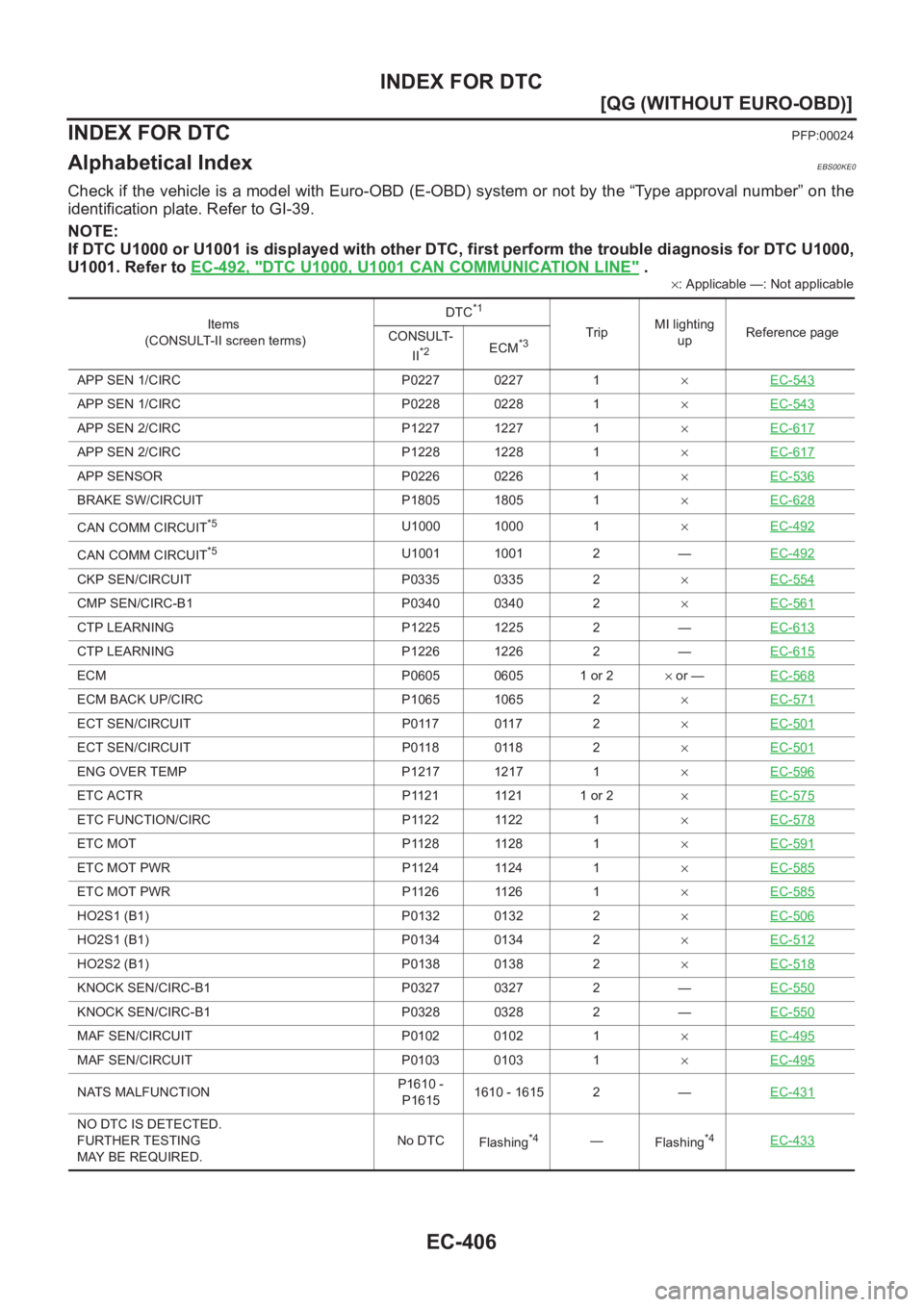
[QG (WITHOUT EURO-OBD)]INDEX FOR DTCPFP:00024
Alphabetical IndexEBS00KE0
Check if the vehicle is a model with Euro-OBD (E-OBD) system or not by the “Type approval number” on the
identification plate. Refer to GI-39.
NOTE:
If DTC U1000 or U1001 is displayed with other DTC, first perform the trouble diagnosis for DTC U1000,
U1001. Refer to EC-492, "
DTC U1000, U1001 CAN COMMUNICATION LINE" .
×: Applicable —: Not applicable
Items
(CONSULT-II screen terms)DTC
*1
TripMI lighting
upReference page
CONSULT-
II
*2ECM*3
APP SEN 1/CIRC P0227 0227 1×EC-543
APP SEN 1/CIRC P0228 0228 1×EC-543
APP SEN 2/CIRC P1227 1227 1×EC-617
APP SEN 2/CIRC P1228 1228 1×EC-617
APP SENSOR P0226 0226 1×EC-536
BRAKE SW/CIRCUIT P1805 1805 1×EC-628
CAN COMM CIRCUIT*5U1000 1000 1×EC-492
CAN COMM CIRCUIT*5U1001 1001 2 —EC-492
CKP SEN/CIRCUIT P0335 0335 2×EC-554
CMP SEN/CIRC-B1 P0340 0340 2×EC-561
CTP LEARNING P1225 1225 2 —EC-613
CTP LEARNING P1226 1226 2 —EC-615
ECM P0605 0605 1 or 2× or —EC-568
ECM BACK UP/CIRC P1065 1065 2×EC-571
ECT SEN/CIRCUIT P0117 0117 2×EC-501
ECT SEN/CIRCUIT P0118 0118 2×EC-501
ENG OVER TEMP P1217 1217 1×EC-596
ETC ACTR P1121 1121 1 or 2×EC-575
ETC FUNCTION/CIRC P1122 1122 1×EC-578
ETC MOT P1128 1128 1×EC-591
ETC MOT PWR P1124 1124 1×EC-585
ETC MOT PWR P1126 1126 1×EC-585
HO2S1 (B1) P0132 0132 2×EC-506
HO2S1 (B1) P0134 0134 2×EC-512
HO2S2 (B1) P0138 0138 2×EC-518
KNOCK SEN/CIRC-B1 P0327 0327 2 —EC-550
KNOCK SEN/CIRC-B1 P0328 0328 2 —EC-550
MAF SEN/CIRCUIT P0102 0102 1×EC-495
MAF SEN/CIRCUIT P0103 0103 1×EC-495
NATS MALFUNCTIONP1610 -
P16151610 - 1615 2 —EC-431
NO DTC IS DETECTED.
FURTHER TESTING
MAY BE REQUIRED.No DTC
Flashing*4—
Flashing*4EC-433
Page 738 of 3189
EC-408
[QG (WITHOUT EURO-OBD)]
INDEX FOR DTC
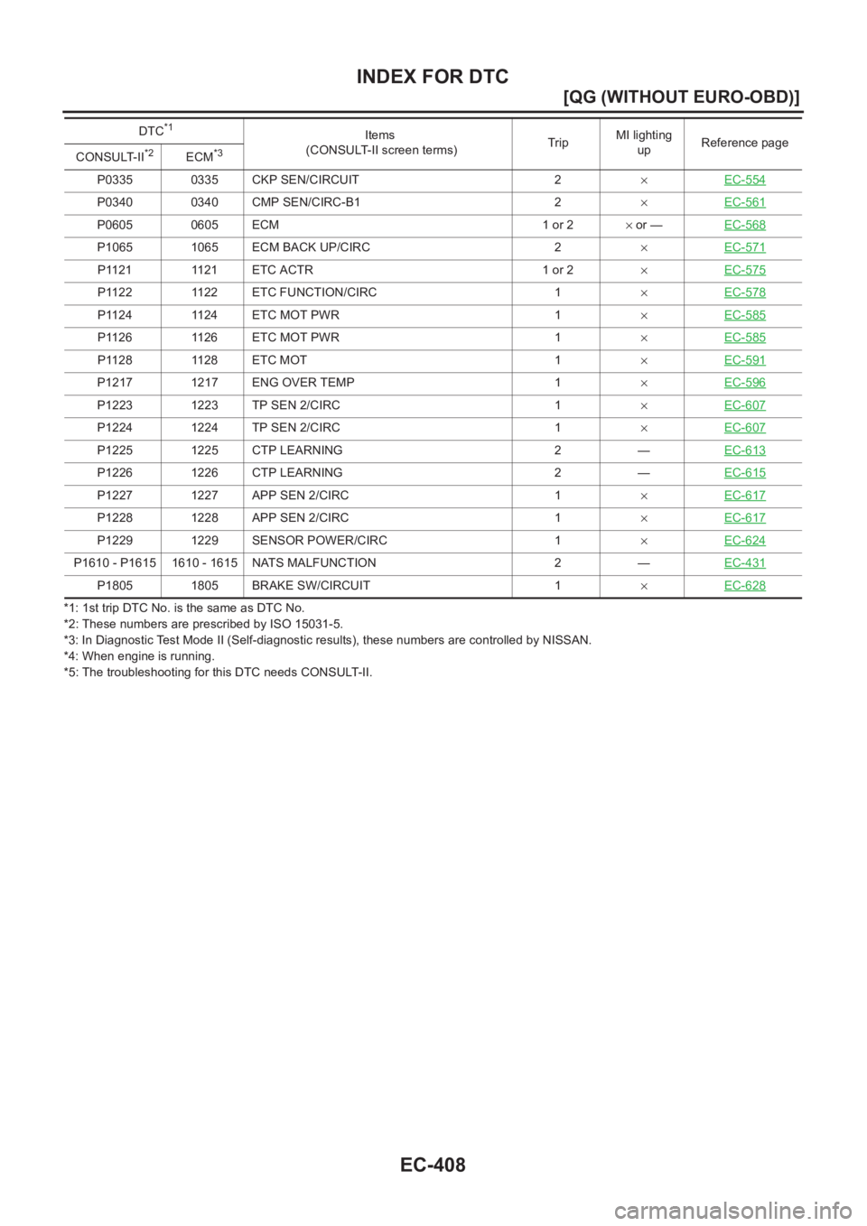
*1: 1st trip DTC No. is the same as DTC No.
*2: These numbers are prescribed by ISO 15031-5.
*3: In Diagnostic Test Mode II (Self-diagnostic results), these numbers are controlled by NISSAN.
*4: When engine is running.
*5: The troubleshooting for this DTC needs CONSULT-II.P0335 0335 CKP SEN/CIRCUIT 2×EC-554
P0340 0340 CMP SEN/CIRC-B1 2×EC-561
P0605 0605 ECM 1 or 2× or —EC-568
P1065 1065 ECM BACK UP/CIRC 2×EC-571
P1121 1121 ETC ACTR 1 or 2×EC-575
P1122 1122 ETC FUNCTION/CIRC 1×EC-578
P1124 1124 ETC MOT PWR 1×EC-585
P1126 1126 ETC MOT PWR 1×EC-585
P1128 1128 ETC MOT 1×EC-591
P1217 1217 ENG OVER TEMP 1×EC-596
P1223 1223 TP SEN 2/CIRC 1×EC-607
P1224 1224 TP SEN 2/CIRC 1×EC-607
P1225 1225 CTP LEARNING 2 —EC-613
P1226 1226 CTP LEARNING 2 —EC-615
P1227 1227 APP SEN 2/CIRC 1×EC-617
P1228 1228 APP SEN 2/CIRC 1×EC-617
P1229 1229 SENSOR POWER/CIRC 1×EC-624
P1610 - P1615 1610 - 1615 NATS MALFUNCTION 2 —EC-431
P1805 1805 BRAKE SW/CIRCUIT 1×EC-628
DTC*1Items
(CONSULT-II screen terms)TripMI lighting
upReference page
CONSULT-II
*2ECM*3