2003 NISSAN ALMERA N16 Engine control circuit
[x] Cancel search: Engine control circuitPage 1512 of 3189
![NISSAN ALMERA N16 2003 Electronic Repair Manual AT-56
[EURO-OBD]
TROUBLE DIAGNOSIS — INTRODUCTION
TROUBLE DIAGNOSIS — INTRODUCTION
PFP:00000
IntroductionECS007NU
The TCM receives a signal from the vehicle speed sensor, throttle
position sensor](/manual-img/5/57350/w960_57350-1511.png "NISSAN ALMERA N16 2003 Electronic Repair Manual AT-56
[EURO-OBD]
TROUBLE DIAGNOSIS — INTRODUCTION
TROUBLE DIAGNOSIS — INTRODUCTION
PFP:00000
IntroductionECS007NU
The TCM receives a signal from the vehicle speed sensor, throttle
position sensor")
AT-56
[EURO-OBD]
TROUBLE DIAGNOSIS — INTRODUCTION
TROUBLE DIAGNOSIS — INTRODUCTION
PFP:00000
IntroductionECS007NU
The TCM receives a signal from the vehicle speed sensor, throttle
position sensor or PNP switch and provides shift control or lock-up
control via A/T solenoid valves.
The TCM also communicates with the ECM by means of a signal
sent from sensing elements used with the EURO-OBD related parts
of the A/T system for malfunction-diagnostic purposes. The TCM is
capable of diagnosing malfunctioning parts while the ECM can store
malfunctions in its memory.
Input and output signals must always be correct and stable in the
operation of the A/T system. The A/T system must be in good oper-
ating condition and be free of valve seizure, solenoid valve malfunc-
tion, etc.
It is much more difficult to diagnose a problem that occurs intermit-
tently rather than continuously. Most intermittent problems are
caused by poor electric connections or improper wiring. In this case,
careful checking of suspected circuits may help prevent the replace-
ment of good parts.
A visual check only, may not find the cause of the problems. A road
test with CONSULT-II (or GST) or a circuit tester connected should
be performed. Follow the “Work Flow”. Refer to AT- 6 0 , "
Work Flow" .
Before undertaking actual checks, take a few minutes to talk with a
customer who approaches with a drive ability complaint. The cus-
tomer can supply good information about such problems, especially
intermittent ones. Find out what symptoms are present and under
what conditions they occur. A “Diagnostic Worksheet” like the exam-
ple (AT- 5 7 , "
DIAGNOSTIC WORKSHEET" ) should be used.
Start your diagnosis by looking for “conventional” problems first. This
will help troubleshoot drive ability problems on an electronically con-
trolled engine vehicle.
Also check related Service bulletins for information.
SAT631IA
SAT632I
SEF234G
Page 1515 of 3189
![NISSAN ALMERA N16 2003 Electronic Repair Manual TROUBLE DIAGNOSIS — INTRODUCTION
AT-59
[EURO-OBD]
D
E
F
G
H
I
J
K
L
MA
B
AT
4. 4-
3.Cruise testAT- 7 4 , "3.
CRUISE
TEST"
AT- 7 8 ,
"Cruise Test
— Part 1"
Part-1
❏ 8. Vehi](/manual-img/5/57350/w960_57350-1514.png "NISSAN ALMERA N16 2003 Electronic Repair Manual TROUBLE DIAGNOSIS — INTRODUCTION
AT-59
[EURO-OBD]
D
E
F
G
H
I
J
K
L
MA
B
AT
4. 4-
3.Cruise testAT- 7 4 , \"3.
CRUISE
TEST\"
AT- 7 8 ,
\"Cruise Test
— Part 1\"
Part-1
❏ 8. Vehi")
TROUBLE DIAGNOSIS — INTRODUCTION
AT-59
[EURO-OBD]
D
E
F
G
H
I
J
K
L
MA
B
AT
4. 4-
3.Cruise testAT- 7 4 , "3.
CRUISE
TEST"
AT- 7 8 ,
"Cruise Test
— Part 1"
Part-1
❏ 8. Vehicle Cannot Be Started From D
1 , AT- 2 2 1 .
❏ 9. A/T Does Not Shift: D
1→ D2 Or Does Not Kickdown: D4→ D2 , AT- 2 2 3 .
❏ 10. A/T Does Not Shift: D
2→ D3 , AT- 2 2 5 .
❏ 11. A/T Does Not Shift: D
3→ D4 , AT-227 .
❏ 12. A/T Does Not Perform Lock-up, AT- 2 3 0
.
❏ 13. A/T Does Not Hold Lock-up Condition, AT- 2 3 1
.
❏ 14. Lock-up Is Not Released, AT- 2 3 2
.
❏ 15. Engine Speed Does Not Return To Idle (Light Braking D
4→ D3 ), AT-233 .
Part-2AT- 8 1 ,
"Cruise Test
— Part 2"❏ 16. Vehicle Does Not Start From D1 , AT- 2 3 4 .
❏ 9. A/T Does Not Shift: D
1→ D2 Or Does Not Kickdown: D4→ D2 , AT- 2 2 3 .
❏ 10. A/T Does Not Shift: D
2→ D3 , AT- 2 2 5 .
❏ 11. A/T Does Not Shift: D
3→ D4 , AT-227 .
Part-3AT- 8 3 ,
"Cruise Test
— Part 3"❏ 17. A/T Does Not Shift: D4→ D3 When Overdrive Control Switch “ON” → “OFF”, AT- 2 3 5 .
❏ 15. Engine Speed Does Not Return To Idle (Light Braking D
4→ D3 ), AT-233 .
❏ 18. A/T Does Not Shift: D
3→ 22 , When Selector Lever “D” → “2” Position, AT-235 .
❏ 15. Engine Speed Does Not Return To Idle (Light Braking D
4→ D3 ), AT-233 .
❏ 19. A/T Does Not Shift: 2
2→ 11 , When Selector Lever “2” → “1” Position, AT-236 .
❏ 20. Vehicle Does Not Decelerate By Engine Brake, AT- 2 3 7
.
❏ 21. TCM Self-diagnosis Does Not Activate (PNP & Overdrive Control Switches, and Throttle Position
Sensor Circuit Checks), AT- 2 3 7
.
❏ SELF-DIAGNOSTIC PROCEDURE/DIAGNOSTIC TROUBLE CODE (DTC) CONFIRMATION PROCE-
DURE — Mark detected items.
❏ PNP switch, AT- 111
.
❏ A/T fluid temperature sensor, AT- 11 7
.
❏ Vehicle speed sensor·A/T (Revolution sensor), AT- 1 2 3
.
❏ Engine speed signal, AT- 1 2 9
.
❏ Torque converter clutch solenoid valve, AT-159
.
❏ Line pressure solenoid valve, AT-164
.
❏ Shift solenoid valve A, AT- 1 7 1
.
❏ Shift solenoid valve B, AT- 1 7 6
.
❏ Accelerator pedal position (APP) sensor, AT-181
.
❏ Overrun clutch solenoid valve, AT- 1 8 7
.
❏ PNP & overdrive control switches, and throttle position sensor, AT- 2 3 7
.
❏ A/T fluid temperature sensor and TCM power source, AT-195
.
❏ Vehicle speed sensor·MTR, AT-201
.
❏ CAN communication line, AT- 1 9 2
❏ Control unit (RAM), control unit (ROM), AT-205 .
❏ Control unit (EEP ROM), AT-207
.
❏ Battery
❏ Others
5.❏ For self-diagnosis NG items, inspect each component. Repair or replace the damaged parts.AT- 5 0 , "
Diag-
nostic Proce-
dure Without
CONSULT-II"
6.❏ Perform all ROAD TEST and re-mark required procedures.AT- 6 8 , "Road
Te s t"
7.❏ Perform DTC CONFIRMATION PROCEDURE for following MI indicating items and check out NG items.
Refer toEC-37, "
Emission-related Diagnostic Information" .EC section
❏ DTC (P0731) A/T 1st gear function, AT- 1 3 3
.
❏ DTC (P0732) A/T 2nd gear function, AT-139
.
❏ DTC (P0733) A/T 3rd gear function, AT- 1 4 5
.
❏ DTC (P0734) A/T 4th gear function, AT- 1 5 1
.
Page 1524 of 3189
![NISSAN ALMERA N16 2003 Electronic Repair Manual AT-68
[EURO-OBD]
TROUBLE DIAGNOSIS — BASIC INSPECTION
JUDGEMENT OF LINE PRESSURE TEST
Road TestECS007NZ
DESCRIPTION
●The purpose of the test is to determine overall performance of A/
T and analyze](/manual-img/5/57350/w960_57350-1523.png "NISSAN ALMERA N16 2003 Electronic Repair Manual AT-68
[EURO-OBD]
TROUBLE DIAGNOSIS — BASIC INSPECTION
JUDGEMENT OF LINE PRESSURE TEST
Road TestECS007NZ
DESCRIPTION
●The purpose of the test is to determine overall performance of A/
T and analyze")
AT-68
[EURO-OBD]
TROUBLE DIAGNOSIS — BASIC INSPECTION
JUDGEMENT OF LINE PRESSURE TEST
Road TestECS007NZ
DESCRIPTION
●The purpose of the test is to determine overall performance of A/
T and analyze causes of problems.
●The road test consists of the following three parts:
1. Check before engine is started
2. Check at idle
3. Cruise test
●Before road test, familiarize yourself with all test procedures and
items to check.
●Conduct tests on all items until specified symptom is found.
Troubleshoot items which check out No Good after road test.
Refer to the following items.
Judgement Suspected parts
At idleLine pressure is low in all positions.
●Oil pump wear
●Control piston damage
●Pressure regulator valve or plug sticking
●Spring for pressure regulator valve damaged
●Line pressure leakage between oil strainer and pressure regulator valve
●Clogged strainer
Line pressure is low in particular posi-
tion.
●Line pressure leakage between manual valve and particular clutch
●For example, line pressure is:
− Low in “R” and “1” positions, but
− Normal in “D” and “2” positions.
Therefore, fluid leakage exists at or around low and reverse brake circuit.
Refer to AT- 1 8 , "
Shift Mechanism" .
Line pressure is high.
●Maladjustment of throttle position sensor
●A/T fluid temperature sensor damaged
●Line pressure solenoid valve sticking
●Short circuit of line pressure solenoid valve circuit
●Pressure modifier valve sticking
●Pressure regulator valve or plug sticking
●Open in dropping resistor circuit
At stall
speedLine pressure is low.
●Maladjustment of throttle position sensor
●Line pressure solenoid valve sticking
●Short circuit of line pressure solenoid valve circuit
●Pressure regulator valve or plug sticking
●Pressure modifier valve sticking
●Pilot valve sticking
SAT786A
SAT496G
Page 1544 of 3189
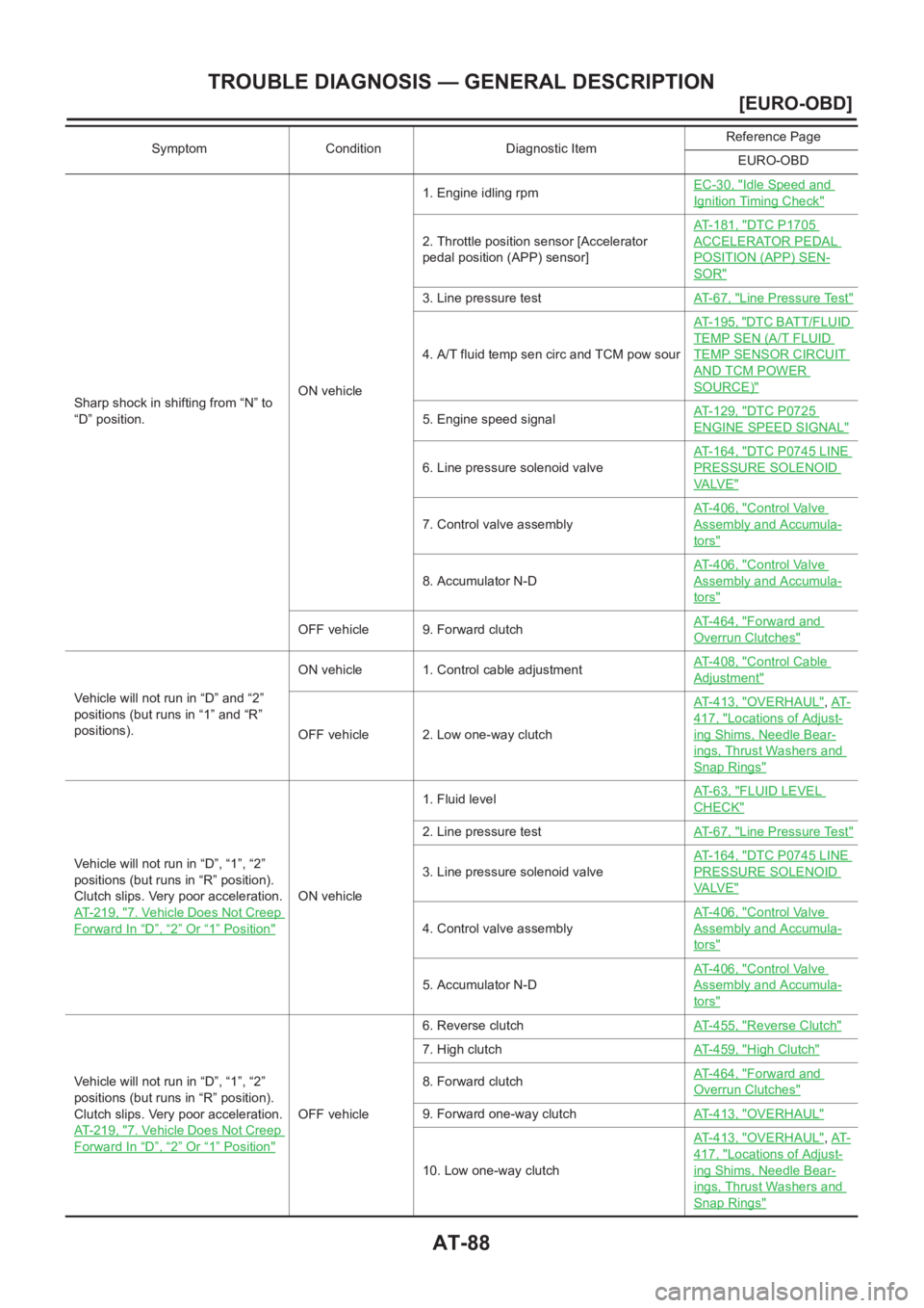
AT-88
[EURO-OBD]
TROUBLE DIAGNOSIS — GENERAL DESCRIPTION
Sharp shock in shifting from “N” to
“D” position.ON vehicle1. Engine idling rpmEC-30, "
Idle Speed and
Ignition Timing Check"
2. Throttle position sensor [Accelerator
pedal position (APP) sensor]AT-181, "
DTC P1705
ACCELERATOR PEDAL
POSITION (APP) SEN-
SOR"
3. Line pressure testAT- 6 7 , "Line Pressure Test"
4. A/T fluid temp sen circ and TCM pow sourAT-195, "
DTC BATT/FLUID
TEMP SEN (A/T FLUID
TEMP SENSOR CIRCUIT
AND TCM POWER
SOURCE)"
5. Engine speed signalAT-129, "DTC P0725
ENGINE SPEED SIGNAL"
6. Line pressure solenoid valveAT-164, "
DTC P0745 LINE
PRESSURE SOLENOID
VA LV E"
7. Control valve assemblyAT-406, "
Control Valve
Assembly and Accumula-
tors"
8. Accumulator N-DAT-406, "
Control Valve
Assembly and Accumula-
tors"
OFF vehicle 9. Forward clutchAT-464, "Forward and
Overrun Clutches"
Vehicle will not run in “D” and “2”
positions (but runs in “1” and “R”
positions).ON vehicle 1. Control cable adjustmentAT-408, "
Control Cable
Adjustment"
OFF vehicle 2. Low one-way clutchAT-413, "
OVERHAUL",AT-
417, "Locations of Adjust-
ing Shims, Needle Bear-
ings, Thrust Washers and
Snap Rings"
Vehicle will not run in “D”, “1”, “2”
positions (but runs in “R” position).
Clutch slips. Very poor acceleration.
AT-219, "
7. Vehicle Does Not Creep
Forward In “D”,“2” Or “1” Position"
ON vehicle1. Fluid levelAT- 6 3 , "
FLUID LEVEL
CHECK"
2. Line pressure testAT- 6 7 , "Line Pressure Test"
3. Line pressure solenoid valveAT-164, "
DTC P0745 LINE
PRESSURE SOLENOID
VA LV E"
4. Control valve assemblyAT-406, "
Control Valve
Assembly and Accumula-
tors"
5. Accumulator N-DAT-406, "
Control Valve
Assembly and Accumula-
tors"
Vehicle will not run in “D”, “1”, “2”
positions (but runs in “R” position).
Clutch slips. Very poor acceleration.
AT-219, "
7. Vehicle Does Not Creep
Forward In “D”,“2” Or “1” Position"
OFF vehicle6. Reverse clutchAT-455, "
Reverse Clutch"
7. High clutchAT-459, "High Clutch"
8. Forward clutchAT-464, "Forward and
Overrun Clutches"
9. Forward one-way clutchAT-413, "OVERHAUL"
10. Low one-way clutchAT-413, "
OVERHAUL",AT-
417, "Locations of Adjust-
ing Shims, Needle Bear-
ings, Thrust Washers and
Snap Rings"
Symptom Condition Diagnostic ItemReference Page
EURO-OBD
Page 1548 of 3189
![NISSAN ALMERA N16 2003 Electronic Repair Manual AT-92
[EURO-OBD]
TROUBLE DIAGNOSIS — GENERAL DESCRIPTION
Engine stops when shifting lever
into “R”, “D”, “2” and “1”.ON vehicle1. Engine idling rpmEC-30, "
Idle Speed and
Ignit](/manual-img/5/57350/w960_57350-1547.png "NISSAN ALMERA N16 2003 Electronic Repair Manual AT-92
[EURO-OBD]
TROUBLE DIAGNOSIS — GENERAL DESCRIPTION
Engine stops when shifting lever
into “R”, “D”, “2” and “1”.ON vehicle1. Engine idling rpmEC-30, \"
Idle Speed and
Ignit")
AT-92
[EURO-OBD]
TROUBLE DIAGNOSIS — GENERAL DESCRIPTION
Engine stops when shifting lever
into “R”, “D”, “2” and “1”.ON vehicle1. Engine idling rpmEC-30, "
Idle Speed and
Ignition Timing Check"
2. Torque converter clutch solenoid valveAT-159, "
DTC P0740
TORQUE CONVERTER
CLUTCH SOLENOID
VA LV E"
3. Control valve assemblyAT-406, "
Control Valve
Assembly and Accumula-
tors"
OFF vehicle 4. Torque converterAT-417, "
Locations of
Adjusting Shims, Needle
Bearings, Thrust Washers
and Snap Rings"
Too sharp a shock in change from
“D
1 ” to “D2 ”.ON vehicle1. Throttle position sensor [Accelerator
pedal position (APP) sensor]AT-181, "
DTC P1705
ACCELERATOR PEDAL
POSITION (APP) SEN-
SOR"
2. Line pressure testAT- 6 7 , "Line Pressure Test"
3. Accumulator servo releaseAT-406, "
Control Valve
Assembly and Accumula-
tors"
4. Control valve assemblyAT-406, "
Control Valve
Assembly and Accumula-
tors"
5. A/T fluid temp sen circ and TCM pow sourAT-195, "
DTC BATT/FLUID
TEMP SEN (A/T FLUID
TEMP SENSOR CIRCUIT
AND TCM POWER
SOURCE)"
OFF vehicle 6. Brake bandAT-483, "Band Servo Pis-
ton Assembly"
Too sharp a shock in change from
“D
2 ” to “D3 ”.ON vehicle1. Throttle position sensor [Accelerator
pedal position (APP) sensor]AT-181, "
DTC P1705
ACCELERATOR PEDAL
POSITION (APP) SEN-
SOR"
2. Line pressure testAT- 6 7 , "Line Pressure Test"
3. Control valve assemblyAT-406, "
Control Valve
Assembly and Accumula-
tors"
OFF vehicle4. High clutchAT-459, "
High Clutch"
5. Brake bandAT-483, "Band Servo Pis-
ton Assembly"
Too sharp a shock in change from
“D
3 ” to “D4 ”.ON vehicle1. Throttle position sensor [Accelerator
pedal position (APP) sensor]AT-181, "
DTC P1705
ACCELERATOR PEDAL
POSITION (APP) SEN-
SOR"
2. Line pressure testAT- 6 7 , "Line Pressure Test"
3. Control valve assemblyAT-406, "
Control Valve
Assembly and Accumula-
tors"
OFF vehicle4. Brake bandAT-483, "
Band Servo Pis-
ton Assembly"
5. Overrun clutchAT-464, "Forward and
Overrun Clutches"
Symptom Condition Diagnostic ItemReference Page
EURO-OBD
Page 1559 of 3189
![NISSAN ALMERA N16 2003 Electronic Repair Manual TROUBLE DIAGNOSIS — GENERAL DESCRIPTION
AT-103
[EURO-OBD]
D
E
F
G
H
I
J
K
L
MA
B
AT
Offensive smell at fluid charging
pipe.ON vehicle 1. Fluid levelAT-63, "
FLUID LEVEL
CHECK"
OFF vehicle2](/manual-img/5/57350/w960_57350-1558.png "NISSAN ALMERA N16 2003 Electronic Repair Manual TROUBLE DIAGNOSIS — GENERAL DESCRIPTION
AT-103
[EURO-OBD]
D
E
F
G
H
I
J
K
L
MA
B
AT
Offensive smell at fluid charging
pipe.ON vehicle 1. Fluid levelAT-63, \"
FLUID LEVEL
CHECK\"
OFF vehicle2")
TROUBLE DIAGNOSIS — GENERAL DESCRIPTION
AT-103
[EURO-OBD]
D
E
F
G
H
I
J
K
L
MA
B
AT
Offensive smell at fluid charging
pipe.ON vehicle 1. Fluid levelAT-63, "
FLUID LEVEL
CHECK"
OFF vehicle2. Torque converterAT-417, "
Locations of
Adjusting Shims, Needle
Bearings, Thrust Washers
and Snap Rings"
3. Oil pumpAT-435, "Oil Pump"
4. Reverse clutchAT-455, "Reverse Clutch"
5. High clutchAT-459, "High Clutch"
6. Brake bandAT-483, "Band Servo Pis-
ton Assembly"
7. Forward clutchAT-464, "Forward and
Overrun Clutches"
8. Overrun clutchAT-464, "Forward and
Overrun Clutches"
9. Low & reverse brakeAT-470, "Low & Reverse
Brake"
Torque converter is not locked up.ON vehicle1. Throttle position sensor [Accelerator
pedal position (APP) sensor]AT-181, "
DTC P1705
ACCELERATOR PEDAL
POSITION (APP) SEN-
SOR"
2. Vehicle speed sensor·A/T (Revolution
sensor) and vehicle speed sensor·MTRAT-123, "
DTC P0720 VEHI-
CLE SPEED SENSOR A/T
(REVOLUTION SEN-
SOR)",AT-201, "DTC
VEHICLE SPEED SEN-
SOR MTR"
3. PNP switch adjustmentAT-408, "
Park/Neutral Posi-
tion (PNP) Switch Adjust-
ment"
4. Engine speed signalAT-129, "DTC P0725
ENGINE SPEED SIGNAL"
5. A/T fluid temp sen circ and TCM pow sourAT-195, "
DTC BATT/FLUID
TEMP SEN (A/T FLUID
TEMP SENSOR CIRCUIT
AND TCM POWER
SOURCE)"
6. Line pressure testAT-67, "Line Pressure Test"
7. Torque converter clutch solenoid valveAT-159, "
DTC P0740
TORQUE CONVERTER
CLUTCH SOLENOID
VA LV E"
8. Control valve assemblyAT-406, "
Control Valve
Assembly and Accumula-
tors"
OFF vehicle 9. Torque converterAT-417, "
Locations of
Adjusting Shims, Needle
Bearings, Thrust Washers
and Snap Rings"
Symptom Condition Diagnostic ItemReference Page
EURO-OBD
Page 1561 of 3189
![NISSAN ALMERA N16 2003 Electronic Repair Manual TROUBLE DIAGNOSIS — GENERAL DESCRIPTION
AT-105
[EURO-OBD]
D
E
F
G
H
I
J
K
L
MA
B
AT
A/T does not shift to “D4 ” when driv-
ing with overdrive control switch
“ON”.ON vehicle1. Throttle posit](/manual-img/5/57350/w960_57350-1560.png "NISSAN ALMERA N16 2003 Electronic Repair Manual TROUBLE DIAGNOSIS — GENERAL DESCRIPTION
AT-105
[EURO-OBD]
D
E
F
G
H
I
J
K
L
MA
B
AT
A/T does not shift to “D4 ” when driv-
ing with overdrive control switch
“ON”.ON vehicle1. Throttle posit")
TROUBLE DIAGNOSIS — GENERAL DESCRIPTION
AT-105
[EURO-OBD]
D
E
F
G
H
I
J
K
L
MA
B
AT
A/T does not shift to “D4 ” when driv-
ing with overdrive control switch
“ON”.ON vehicle1. Throttle position sensor [Accelerator
pedal position (APP) sensor]AT-181, "
DTC P1705
ACCELERATOR PEDAL
POSITION (APP) SEN-
SOR"
2. PNP switch adjustmentAT-408, "
Park/Neutral Posi-
tion (PNP) Switch Adjust-
ment"
3. Vehicle speed sensor·A/T (Revolution
sensor) and vehicle speed sensor·MTRAT-123, "
DTC P0720 VEHI-
CLE SPEED SENSOR A/T
(REVOLUTION SEN-
SOR)",AT-201, "DTC
VEHICLE SPEED SEN-
SOR MTR"
4. Shift solenoid valve AAT-171, "
DTC P0750
SHIFT SOLENOID VALVE
A"
5. Overrun clutch solenoid valveAT-187, "
DTC P1760
OVERRUN CLUTCH
SOLENOID VALVE"
6. Control valve assemblyAT-406, "
Control Valve
Assembly and Accumula-
tors"
7. A/T fluid temp sen circ and TCM pow sourAT-195, "
DTC BATT/FLUID
TEMP SEN (A/T FLUID
TEMP SENSOR CIRCUIT
AND TCM POWER
SOURCE)"
8. Line pressure testAT-67, "Line Pressure Test"
OFF vehicle9. Brake bandAT-483, "
Band Servo Pis-
ton Assembly"
10. Overrun clutchAT-464, "Forward and
Overrun Clutches"
Engine is stopped at “R”, “D”, “2”
and “1” positions.ON vehicle1. Fluid levelAT-63, "
FLUID LEVEL
CHECK"
2. Torque converter clutch solenoid valveAT-159, "
DTC P0740
TORQUE CONVERTER
CLUTCH SOLENOID
VA LV E"
3. Shift solenoid valve AAT-171, "
DTC P0750
SHIFT SOLENOID VALVE
A"
4. Shift solenoid valve BAT-176, "
DTC P0755
SHIFT SOLENOID VALVE
B"
5. Control valve assemblyAT-406, "
Control Valve
Assembly and Accumula-
tors"
Symptom Condition Diagnostic ItemReference Page
EURO-OBD
Page 1589 of 3189
![NISSAN ALMERA N16 2003 Electronic Repair Manual DTC P0731 A/T 1ST GEAR FUNCTION
AT-133
[EURO-OBD]
D
E
F
G
H
I
J
K
L
MA
B
AT
DTC P0731 A/T 1ST GEAR FUNCTIONPFP:31940
DescriptionECS007OI
●This is an OBD-II self-diagnostic item and not available in](/manual-img/5/57350/w960_57350-1588.png "NISSAN ALMERA N16 2003 Electronic Repair Manual DTC P0731 A/T 1ST GEAR FUNCTION
AT-133
[EURO-OBD]
D
E
F
G
H
I
J
K
L
MA
B
AT
DTC P0731 A/T 1ST GEAR FUNCTIONPFP:31940
DescriptionECS007OI
●This is an OBD-II self-diagnostic item and not available in")
DTC P0731 A/T 1ST GEAR FUNCTION
AT-133
[EURO-OBD]
D
E
F
G
H
I
J
K
L
MA
B
AT
DTC P0731 A/T 1ST GEAR FUNCTIONPFP:31940
DescriptionECS007OI
●This is an OBD-II self-diagnostic item and not available in TCM self-diagnosis.
●This malfunction will not be detected while the O/D OFF indicator lamp is indicating another self-diagnosis
malfunction.
●This malfunction is detected when the A/T does not shift into first gear position as instructed by the TCM.
This is not caused by electrical malfunction (circuits open or shorted) but by mechanical malfunction such
as control valve sticking, improper solenoid valve operation, etc.
TCM TERMINALS AND REFERENCE VALUE
Remarks: Specification data are reference values.
ON BOARD DIAGNOSTIC LOGIC
This diagnosis monitors actual gear position by checking the torque converter slip ratio calculated by TCM as
follows:
Torque converter slip ratio = A x C/B
A: Output shaft revolution signal from revolution sensor
B: Engine speed signal from ECM
C: Gear ratio determined as gear position which TCM supposes
If the actual gear position is higher than the position (1st) supposed by TCM, the slip ratio will be more than
normal. In case the ratio exceeds the specified value, TCM judges this diagnosis malfunction.
This malfunction will be caused when either shift solenoid valve A is stuck open or shift solenoid valve B is
stuck open.
*: P0731 is detected.Gear position 1 2 3 4
Shift solenoid valve A ON (Closed) OFF (Open) OFF (Open) ON (Closed)
Shift solenoid valve B ON (Closed) ON (Closed) OFF (Open) OFF (Open)
Te r m i -
nal No.Wire color Item ConditionJudgement stan-
dard
(Approx.)
11 L / WShift solenoid
valve AWhen shift solenoid valve A oper-
ates.
(When driving in “D
1 ” or “D4 ”.)Battery voltage
When shift solenoid valve A does not
operate.
(When driving in “D
2 ” or “D3 ”.)0V
12 L/YShift solenoid
valve BWhen shift solenoid valve B oper-
ates.
(When driving in “D
1 ” or “D2 ”.)Battery voltage
When shift solenoid valve B does not
operate.
(When driving in “D
3 ” or “D4 ”.)0V
Gear position supposed by TCM 1 2 3 4
In case of gear position with no malfunctions 1 2 3 4
In case of gear position with shift solenoid valve A stuck open2* 2 3 3
In case of gear position with shift solenoid valve B stuck open4* 3 3 4
Diagnostic trouble code Malfunction is detected when... Check items (Possible cause)
: A/T 1ST GR FNCTN
A/T cannot be shifted to the 1st gear posi-
tion even if electrical circuit is good.
●Shift solenoid valve A
●Shift solenoid valve B
●Each clutch
●Hydraulic control circuit : P0731