2003 NISSAN ALMERA N16 Engine control circuit
[x] Cancel search: Engine control circuitPage 1178 of 3189
SEF437Y
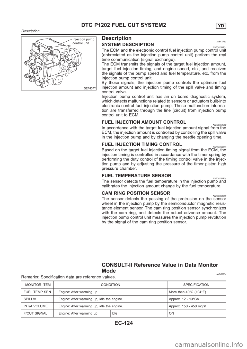
DescriptionNJEC0753SYSTEM DESCRIPTIONNJEC0753S01The ECM and the electronic control fuel injection pump control unit
(abbreviated as the injection pump control unit) perform the real
time communication (signal exchange).
The ECM transmits the signals of the target fuel injection amount,
target fuel injection timing, and engine speed, etc., and receives
the signals of the pump speed and fuel temperature, etc. from the
injection pump control unit.
By those signals, the injection pump controls the optimum fuel
injection amount and injection timing of the spill valve and timing
control valve.
Injection pump control unit has an on board diagnostic system,
which detects malfunctions related to sensors or actuators built-into
electronic control fuel injection pump. These malfunction informa-
tion are transferred through the line (circuit) from injection pump
control unit to ECM.
FUEL INJECTION AMOUNT CONTROLNJEC0753S02In accordance with the target fuel injection amount signal from the
ECM, the injection amount is controlled by controlling the spill valve
in the injection pump and by changing the needle opening time.
FUEL INJECTION TIMING CONTROLNJEC0753S03Based on the target fuel injection timing signal from the ECM, the
injection timing is controlled in accordance with the timer spring by
performing the duty control of the timing control valve in the injec-
tion pump and by adjusting the pressure of the timer piston high
pressure chamber.
FUEL TEMPERATURE SENSORNJEC0753S04The sensor detects the fuel temperature in the injection pump and
calibrates the injection amount change by the fuel temperature.
CAM RING POSITION SENSORNJEC0753S05The sensor detects the passing of the protrusion on the sensor
wheel in the injection pump by the semiconductor magnetic resis-
tance element sensor. The cam ring position sensor synchronizes
with the cam ring, and detects the actual advance amount. The
injection pump control unit measures the injection pump revolution
by the signal of the cam ring position sensor.
CONSULT-II Reference Value in Data Monitor
Mode
NJEC0754Remarks: Specification data are reference values.
MONITOR ITEM CONDITION SPECIFICATION
FUEL TEMP SEN Engine: After warming up More than 40°C (104°F)
SPILL/V Engine: After warming up, idle the engine. Approx. 12 - 13°CA
INT/A VOLUME Engine: After warming up, idle the engine. Approx. 150 - 450 mg/st
F/CUT SIGNAL Engine: After warming up Idle ON
DTC P1202 FUEL CUT SYSTEM2YD
Description
EC-124
Page 1179 of 3189
MONITOR ITEM CONDITION SPECIFICATION
BARO SEN Ignition switch: ONAltitude
Approx. 0 m (0 ft): Approx. 100.62
kPa (1.0062 bar, 1.026 kg/cm
2,
14.59 psi)
Approx. 1,000 m (3,281 ft): Approx.
88.95 kPa (0.8895 bar, 0.907
kg/cm
2, 12.90 psi)
Approx. 1,500 m (4,922 ft): Approx.
83.16 kPa (0.8316 bar, 0.848
kg/cm
2, 12.06 psi)
Approx. 2,000 m (6,562 ft): Approx.
78.36 kPa (0.7836 bar, 0.799
kg/cm
2, 11.36 psi)
ECM Terminals and Reference ValueNJEC0755Specification data are reference values and are measured between each terminal and ground.
CAUTION:
Do not use ECM ground terminals when measuring input/output voltage. Doing so may result in dam-
age to the ECM’s transistor. Use a ground other than ECM terminals, such as the ground.
TERMI-
NAL
NO.WIRE
COLORITEM CONDITION DATA (DC Voltage)
313 L/WElectronic control fuel
injection pump[Engine is running]
Warm-up condition
Idle speedApproximately 0.1V
314 L/RElectronic control fuel
injection pump[Engine is running]
Warm-up condition
Idle speedApproximately 0.4V
316 PUElectronic control fuel
injection pump[Engine is running]
Warm-up condition
Idle speedApproximately 2.5V
317 PElectronic control fuel
injection pump[Engine is running]
Warm-up condition
Idle speedApproximately 2.5V
On Board Diagnosis LogicNJEC0756This self-diagnosis has the one trip detection logic.
DTC Malfunction is detected when .... Check Items (Possible cause)
P1202
1002Fuel cut control system does not function properly. Harness or connectors
(Electronic control fuel circuit is open or shorted.)
Electronic control fuel
SEF817Y
DTC Confirmation ProcedureNJEC0757WITH CONSULT-IINJEC0757S011) Turn ignition switch “ON” and wait at least 2 seconds.
2) Select “DATA MONITOR” mode with CONSULT-II.
3) Start engine and run it for at least 2 seconds at idle speed.
(If engine does not run, turn ignition switch to “START” for at
least 2 seconds.)
4) Turn ignition switch “OFF”, wait at least 5 seconds and then
turn “ON”.
5) If DTC is detected, go to “Diagnostic Procedure”, EC-128.
GI
MA
EM
LC
FE
CL
MT
AT
AX
SU
BR
ST
RS
BT
HA
SC
EL
IDX
DTC P1202 FUEL CUT SYSTEM2YD
CONSULT-II Reference Value in Data Monitor Mode (Cont’d)
EC-125
Page 1189 of 3189
4 CHECK COOLING FAN LOW SPEED OPERATION
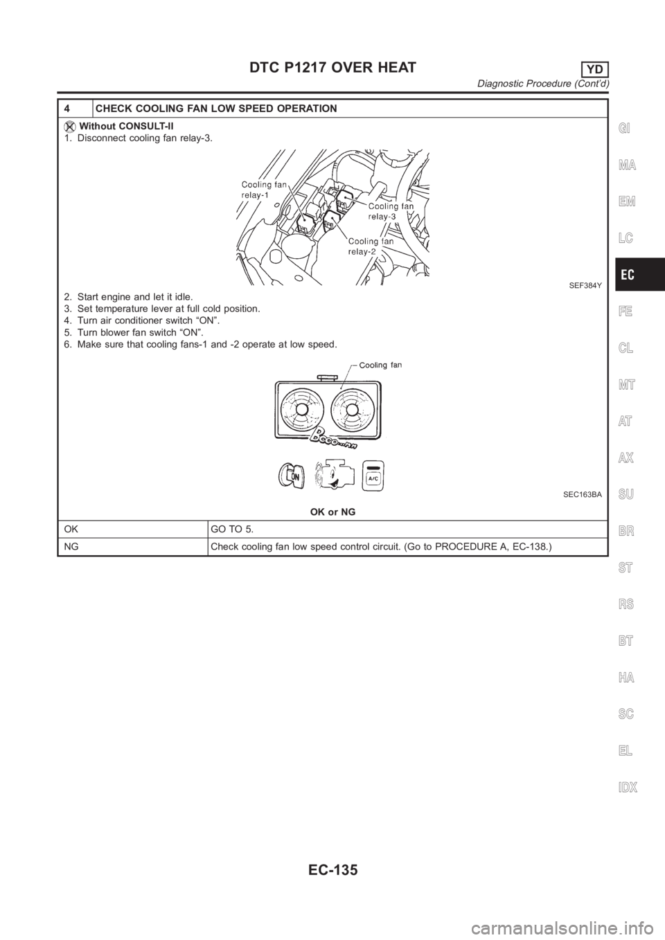
Without CONSULT-II
1. Disconnect cooling fan relay-3.
SEF384Y
2. Start engine and let it idle.
3. Set temperature lever at full cold position.
4. Turn air conditioner switch “ON”.
5. Turn blower fan switch “ON”.
6. Make sure that cooling fans-1 and -2 operate at low speed.
SEC163BA
OK or NG
OK GO TO 5.
NG Check cooling fan low speed control circuit. (Go to PROCEDURE A, EC-138.)
GI
MA
EM
LC
FE
CL
MT
AT
AX
SU
BR
ST
RS
BT
HA
SC
EL
IDX
DTC P1217 OVER HEATYD
Diagnostic Procedure (Cont’d)
EC-135
Page 1190 of 3189
5 CHECK COOLING FAN HIGH SPEED OPERATION
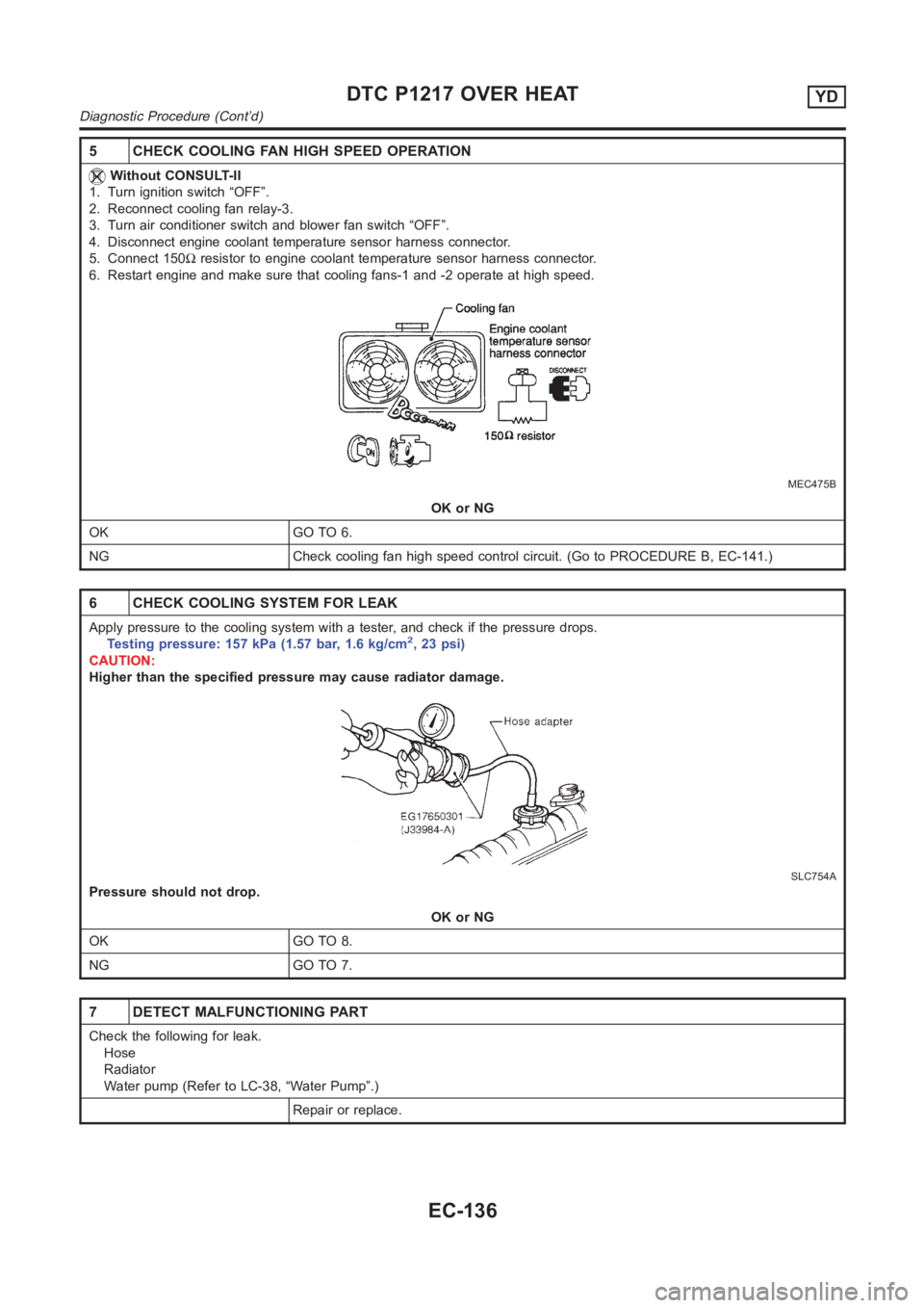
Without CONSULT-II
1. Turn ignition switch “OFF”.
2. Reconnect cooling fan relay-3.
3. Turn air conditioner switch and blower fan switch “OFF”.
4. Disconnect engine coolant temperature sensor harness connector.
5. Connect 150Ωresistor to engine coolant temperature sensor harness connector.
6. Restart engine and make sure that cooling fans-1 and -2 operate at high speed.
MEC475B
OK or NG
OK GO TO 6.
NG Check cooling fan high speed control circuit. (Go to PROCEDURE B, EC-141.)
6 CHECK COOLING SYSTEM FOR LEAK
Apply pressure to the cooling system with a tester, and check if the pressure drops.
Testing pressure: 157 kPa (1.57 bar, 1.6 kg/cm2,23psi)
CAUTION:
Higher than the specified pressure may cause radiator damage.
SLC754A
Pressure should not drop.
OK or NG
OK GO TO 8.
NG GO TO 7.
7 DETECT MALFUNCTIONING PART
Check the following for leak.
Hose
Radiator
Water pump (Refer to LC-38, “Water Pump”.)
Repair or replace.
DTC P1217 OVER HEATYD
Diagnostic Procedure (Cont’d)
EC-136
Page 1199 of 3189
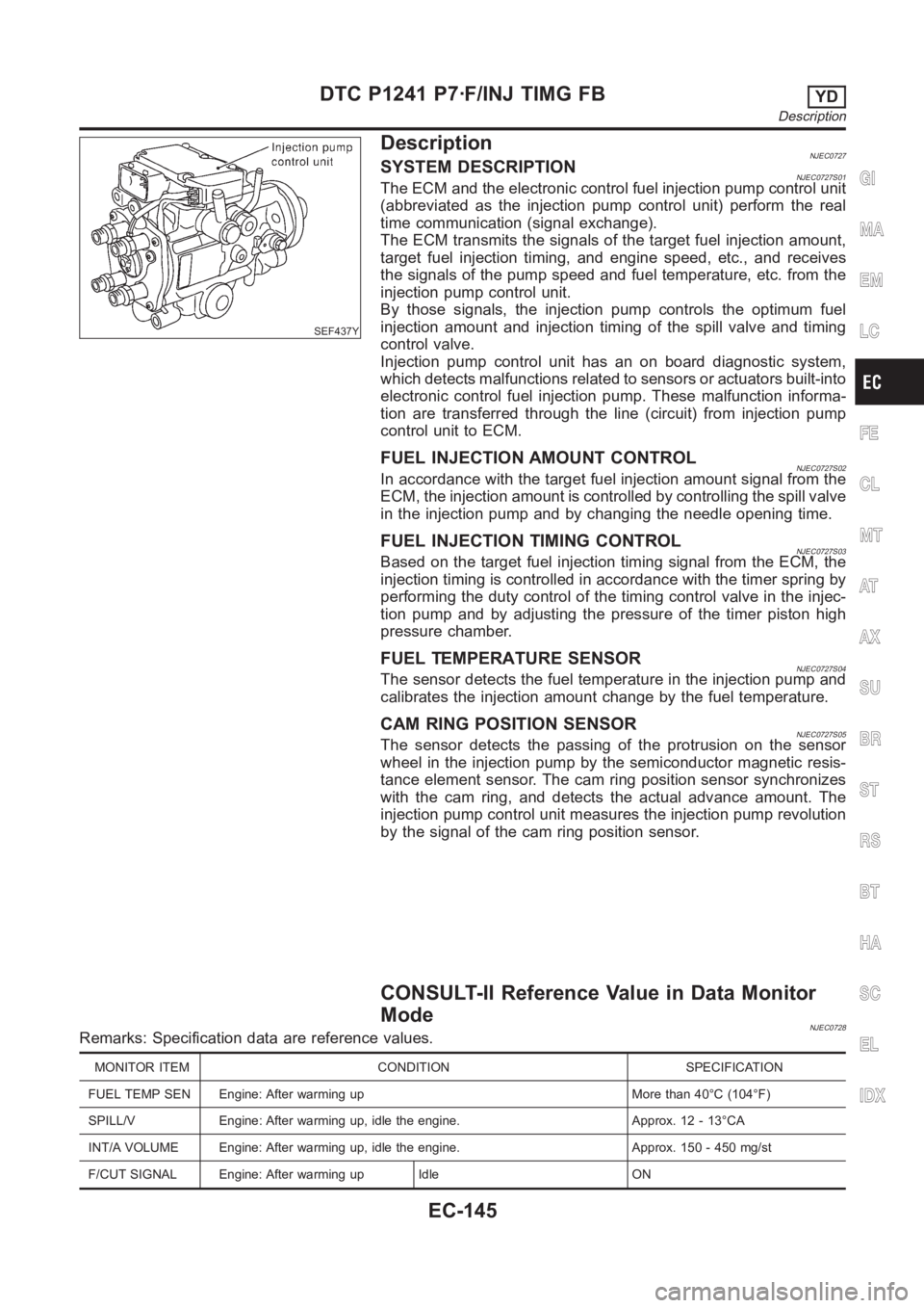
SEF437Y
DescriptionNJEC0727SYSTEM DESCRIPTIONNJEC0727S01The ECM and the electronic control fuel injection pump control unit
(abbreviated as the injection pump control unit) perform the real
time communication (signal exchange).
The ECM transmits the signals of the target fuel injection amount,
target fuel injection timing, and engine speed, etc., and receives
the signals of the pump speed and fuel temperature, etc. from the
injection pump control unit.
By those signals, the injection pump controls the optimum fuel
injection amount and injection timing of the spill valve and timing
control valve.
Injection pump control unit has an on board diagnostic system,
which detects malfunctions related to sensors or actuators built-into
electronic control fuel injection pump. These malfunction informa-
tion are transferred through the line (circuit) from injection pump
control unit to ECM.
FUEL INJECTION AMOUNT CONTROLNJEC0727S02In accordance with the target fuel injection amount signal from the
ECM, the injection amount is controlled by controlling the spill valve
in the injection pump and by changing the needle opening time.
FUEL INJECTION TIMING CONTROLNJEC0727S03Based on the target fuel injection timing signal from the ECM, the
injection timing is controlled in accordance with the timer spring by
performing the duty control of the timing control valve in the injec-
tion pump and by adjusting the pressure of the timer piston high
pressure chamber.
FUEL TEMPERATURE SENSORNJEC0727S04The sensor detects the fuel temperature in the injection pump and
calibrates the injection amount change by the fuel temperature.
CAM RING POSITION SENSORNJEC0727S05The sensor detects the passing of the protrusion on the sensor
wheel in the injection pump by the semiconductor magnetic resis-
tance element sensor. The cam ring position sensor synchronizes
with the cam ring, and detects the actual advance amount. The
injection pump control unit measures the injection pump revolution
by the signal of the cam ring position sensor.
CONSULT-II Reference Value in Data Monitor
Mode
NJEC0728Remarks: Specification data are reference values.
MONITOR ITEM CONDITION SPECIFICATION
FUEL TEMP SEN Engine: After warming up More than 40°C (104°F)
SPILL/V Engine: After warming up, idle the engine. Approx. 12 - 13°CA
INT/A VOLUME Engine: After warming up, idle the engine. Approx. 150 - 450 mg/st
F/CUT SIGNAL Engine: After warming up Idle ON
GI
MA
EM
LC
FE
CL
MT
AT
AX
SU
BR
ST
RS
BT
HA
SC
EL
IDX
DTC P1241 P7·F/INJ TIMG FBYD
Description
EC-145
Page 1200 of 3189
MONITOR ITEM CONDITION SPECIFICATION
BARO SEN Ignition switch: ONAltitude
Approx. 0 m (0 ft): Approx. 100.62
kPa (1.0062 bar, 1.026 kg/cm
2,
14.59 psi)
Approx. 1,000 m (3,281 ft): Approx.
88.95 kPa (0.8895 bar, 0.907
kg/cm
2, 12.90 psi)
Approx. 1,500 m (4,922 ft): Approx.
83.16 kPa (0.8316 bar, 0.848
kg/cm
2, 12.06 psi)
Approx. 2,000 m (6,562 ft): Approx.
78.36 kPa (0.7836 bar, 0.799
kg/cm
2, 11.36 psi)
ECM Terminals and Reference ValueNJEC0729Specification data are reference values and are measured between each terminal and ground.
CAUTION:
Do not use ECM ground terminals when measuring input/output voltage. Doing so may result in dam-
age to the ECM’s transistor. Use a ground other than ECM terminals, such as the ground.
TERMI-
NAL
NO.WIRE
COLORITEM CONDITION DATA (DC Voltage)
313 L/WElectronic control fuel
injection pump[Engine is running]
Warm-up condition
Idle speedApproximately 0.1V
314 L/RElectronic control fuel
injection pump[Engine is running]
Warm-up condition
Idle speedApproximately 0.4V
316 PUElectronic control fuel
injection pump[Engine is running]
Warm-up condition
Idle speedApproximately 2.5V
317 PElectronic control fuel
injection pump[Engine is running]
Warm-up condition
Idle speedApproximately 2.5V
On Board Diagnosis LogicNJEC0730This self-diagnosis has the one trip detection logic.
DTC Malfunction is detected when .... Check Items (Possible cause)
P1241
0707Fuel injection timing control system does not
function properly.Harness or connectors
(Electronic control fuel injection pump circuit is
open or shorted.)
Electronic control fuel injection pump
Improper fuel quality
SEF817Y
DTC Confirmation ProcedureNJEC0731WITH CONSULT-IINJEC0731S011) Turn ignition switch “ON” and wait at least 2 seconds.
2) Select “DATA MONITOR” mode with CONSULT-II.
3) Start engine and run it for at least 2 seconds at idle speed.
(If engine does not run, turn ignition switch to “START” for at
least 2 seconds.)
4) Keep engine speed at more than 2,000 rpm for at least 10
seconds.
5) If DTC is detected, go to “Diagnostic Procedure”, EC-149.
DTC P1241 P7·F/INJ TIMG FBYD
CONSULT-II Reference Value in Data Monitor Mode (Cont’d)
EC-146
Page 1205 of 3189
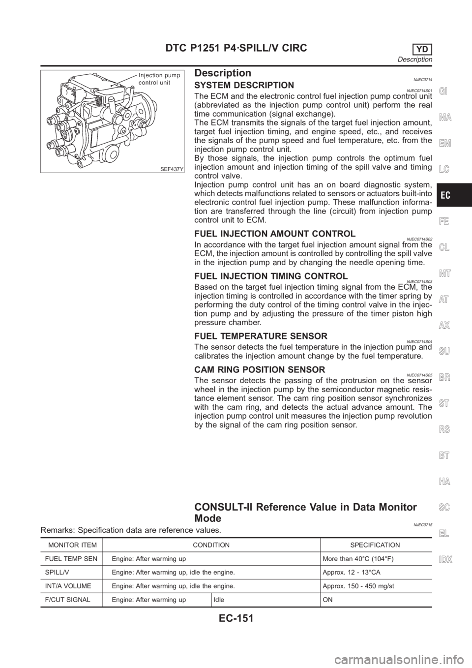
SEF437Y
DescriptionNJEC0714SYSTEM DESCRIPTIONNJEC0714S01The ECM and the electronic control fuel injection pump control unit
(abbreviated as the injection pump control unit) perform the real
time communication (signal exchange).
The ECM transmits the signals of the target fuel injection amount,
target fuel injection timing, and engine speed, etc., and receives
the signals of the pump speed and fuel temperature, etc. from the
injection pump control unit.
By those signals, the injection pump controls the optimum fuel
injection amount and injection timing of the spill valve and timing
control valve.
Injection pump control unit has an on board diagnostic system,
which detects malfunctions related to sensors or actuators built-into
electronic control fuel injection pump. These malfunction informa-
tion are transferred through the line (circuit) from injection pump
control unit to ECM.
FUEL INJECTION AMOUNT CONTROLNJEC0714S02In accordance with the target fuel injection amount signal from the
ECM, the injection amount is controlled by controlling the spill valve
in the injection pump and by changing the needle opening time.
FUEL INJECTION TIMING CONTROLNJEC0714S03Based on the target fuel injection timing signal from the ECM, the
injection timing is controlled in accordance with the timer spring by
performing the duty control of the timing control valve in the injec-
tion pump and by adjusting the pressure of the timer piston high
pressure chamber.
FUEL TEMPERATURE SENSORNJEC0714S04The sensor detects the fuel temperature in the injection pump and
calibrates the injection amount change by the fuel temperature.
CAM RING POSITION SENSORNJEC0714S05The sensor detects the passing of the protrusion on the sensor
wheel in the injection pump by the semiconductor magnetic resis-
tance element sensor. The cam ring position sensor synchronizes
with the cam ring, and detects the actual advance amount. The
injection pump control unit measures the injection pump revolution
by the signal of the cam ring position sensor.
CONSULT-II Reference Value in Data Monitor
Mode
NJEC0715Remarks: Specification data are reference values.
MONITOR ITEM CONDITION SPECIFICATION
FUEL TEMP SEN Engine: After warming up More than 40°C (104°F)
SPILL/V Engine: After warming up, idle the engine. Approx. 12 - 13°CA
INT/A VOLUME Engine: After warming up, idle the engine. Approx. 150 - 450 mg/st
F/CUT SIGNAL Engine: After warming up Idle ON
GI
MA
EM
LC
FE
CL
MT
AT
AX
SU
BR
ST
RS
BT
HA
SC
EL
IDX
DTC P1251 P4·SPILL/V CIRCYD
Description
EC-151
Page 1206 of 3189
MONITOR ITEM CONDITION SPECIFICATION
BARO SEN Ignition switch: ONAltitude
Approx. 0 m (0 ft): Approx. 100.62
kPa (1.0062 bar, 1.026 kg/cm
2,
14.59 psi)
Approx. 1,000 m (3,281 ft): Approx.
88.95 kPa (0.8895 bar, 0.907
kg/cm
2, 12.90 psi)
Approx. 1,500 m (4,922 ft): Approx.
83.16 kPa (0.8316 bar, 0.848
kg/cm
2, 12.06 psi)
Approx. 2,000 m (6,562 ft): Approx.
78.36 kPa (0.7836 bar, 0.799
kg/cm
2, 11.36 psi)
ECM Terminals and Reference ValueNJEC0716Specification data are reference values and are measured between each terminal and ground.
CAUTION:
Do not use ECM ground terminals when measuring input/output voltage. Doing so may result in dam-
age to the ECM’s transistor. Use a ground other than ECM terminals, such as the ground.
TERMI-
NAL
NO.WIRE
COLORITEM CONDITION DATA (DC Voltage)
313 L/WElectronic control fuel
injection pump[Engine is running]
Warm-up condition
Idle speedApproximately 0.1V
314 L/RElectronic control fuel
injection pump[Engine is running]
Warm-up condition
Idle speedApproximately 0.4V
316 PUElectronic control fuel
injection pump[Engine is running]
Warm-up condition
Idle speedApproximately 2.5V
317 PElectronic control fuel
injection pump[Engine is running]
Warm-up condition
Idle speedApproximately 2.5V
On Board Diagnosis LogicNJEC0717This self-diagnosis has the one trip detection logic.
DTC Malfunction is detected when .... Check Items (Possible cause)
P1251
0704Spill valve (Built-into electronic control fuel injec-
tion pump) does not function properly.Harness or connectors
(Electronic control fuel injection pump circuit is
open or shorted.)
Electronic control fuel injection pump
SEF817Y
DTC Confirmation ProcedureNJEC0718WITH CONSULT-IINJEC0718S011) Turn ignition switch “ON” and wait at least 2 seconds.
2) Select “DATA MONITOR” mode with CONSULT-II.
3) Start engine and run it for at least 2 seconds at idle speed.
(If engine does not run, turn ignition switch to “START” for at
least 2 seconds.)
4) If DTC is detected, go to “Diagnostic Procedure”, EC-155.
WITHOUT CONSULT-IINJEC0718S021) Turn ignition switch “ON” and wait at least 2 seconds.
DTC P1251 P4·SPILL/V CIRCYD
CONSULT-II Reference Value in Data Monitor Mode (Cont’d)
EC-152