2003 NISSAN ALMERA N16 Engine control circuit
[x] Cancel search: Engine control circuitPage 1254 of 3189
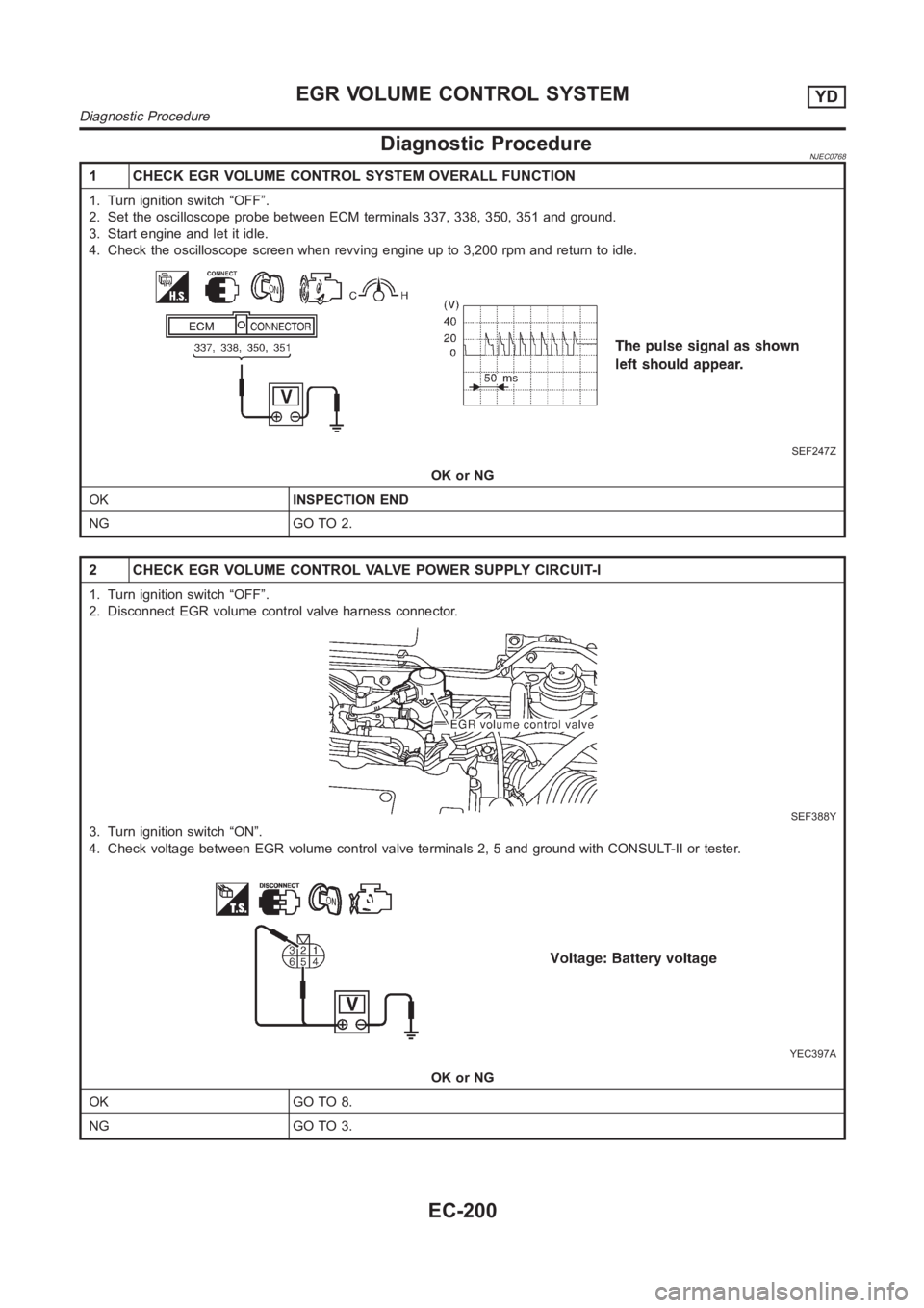
Diagnostic ProcedureNJEC0768
1 CHECK EGR VOLUME CONTROL SYSTEM OVERALL FUNCTION
1. Turn ignition switch “OFF”.
2. Set the oscilloscope probe between ECM terminals 337, 338, 350, 351 and ground.
3. Start engine and let it idle.
4. Check the oscilloscope screen when revving engine up to 3,200 rpm and return to idle.
SEF247Z
OK or NG
OKINSPECTION END
NG GO TO 2.
2 CHECK EGR VOLUME CONTROL VALVE POWER SUPPLY CIRCUIT-I
1. Turn ignition switch “OFF”.
2. Disconnect EGR volume control valve harness connector.
SEF388Y
3. Turn ignition switch “ON”.
4. Check voltage between EGR volume control valve terminals 2, 5 and groundwith CONSULT-II or tester.
YEC397A
OK or NG
OK GO TO 8.
NG GO TO 3.
EGR VOLUME CONTROL SYSTEMYD
Diagnostic Procedure
EC-200
Page 1255 of 3189
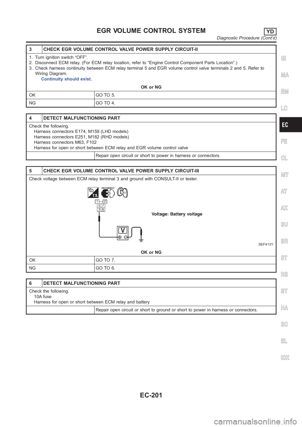
3 CHECK EGR VOLUME CONTROL VALVE POWER SUPPLY CIRCUIT-II
1. Turn ignition switch “OFF”.
2. Disconnect ECM relay. (For ECM relay location, refer to “Engine ControlComponent Parts Location”.)
3. Check harness continuity between ECM relay terminal 5 and EGR volume control valve terminals 2 and 5. Refer to
Wiring Diagram.
Continuity should exist.
OK or NG
OK GO TO 5.
NG GO TO 4.
4 DETECT MALFUNCTIONING PART
Check the following.
Harness connectors E174, M159 (LHD models)
Harness connectors E251, M182 (RHD models)
Harness connectors M63, F102
Harness for open or short between ECM relay and EGR volume control valve
Repair open circuit or short to power in harness or connectors.
5 CHECK EGR VOLUME CONTROL VALVE POWER SUPPLY CIRCUIT-III
Check voltage between ECM relay terminal 3 and ground with CONSULT-II or tester.
SEF413Y
OK or NG
OK GO TO 7.
NG GO TO 6.
6 DETECT MALFUNCTIONING PART
Check the following.
10A fuse
Harness for open or short between ECM relay and battery
Repair open circuit or short to ground or short to power in harness or connectors.
GI
MA
EM
LC
FE
CL
MT
AT
AX
SU
BR
ST
RS
BT
HA
SC
EL
IDX
EGR VOLUME CONTROL SYSTEMYD
Diagnostic Procedure (Cont’d)
EC-201
Page 1457 of 3189
AT-1
AUTOMATIC TRANSAXLE
C TRANSMISSION/TRANSAXLE
CONTENTS
D
E
F
G
H
I
J
K
L
M
SECTION
A
B
AT
AUTOMATIC TRANSAXLE
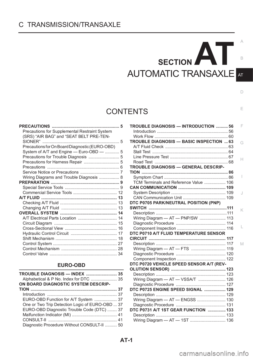
PRECAUTIONS .......................................................... 5
Precautions for Supplemental Restraint System
(SRS) “AIR BAG” and “SEAT BELT PRE-TEN-
SIONER” .................................................................. 5
Precautions for On Board Diagnostic (EURO-OBD)
System of A/T and Engine — Euro-OBD — ............. 5
Precautions for Trouble Diagnosis ........................... 5
Precautions for Harness Repair ............................... 5
Precautions .............................................................. 6
Service Notice or Precautions .................................. 7
Wiring Diagrams and Trouble Diagnosis .................. 8
PREPARATION ........................................................... 9
Special Service Tools ............................................... 9
Commercial Service Tools ...................................... 12
A/T FLUID ................................................................. 13
Checking A/T Fluid ................................................. 13
Changing A/T Fluid ............................................. ... 13
OVERALL SYSTEM ................................................. 14
A/T Electrical Parts Location .................................. 14
Circuit Diagram ...................................................... 15
Cross-Sectional View ............................................. 16
Hydraulic Control Circuit ........................................ 17
Shift Mechanism ..................................................... 18
Control System ....................................................... 27
Control Mechanism ................................................ 28
Control Valve .......................................................... 34
EURO-OBD
TROUBLE DIAGNOSIS — INDEX ........................... 35
Alphabetical & P No. Index for DTC ....................... 35
ON BOARD DIAGNOSTIC SYSTEM DESCRIP-
TION .......................................................................... 37
Introduction ............................................................ 37
EURO-OBD Function for A/T System .................... 37
One or Two Trip Detection Logic of EURO-OBD ... 37
EURO-OBD Diagnostic Trouble Code (DTC) ......... 37
Malfunction Indicator (MI) ....................................... 41
CONSULT-II ........................................................... 41
Diagnostic Procedure Without CONSULT-II ........... 50TROUBLE DIAGNOSIS — INTRODUCTION ........... 56
Introduction ............................................................. 56
Work Flow ............................................................... 60
TROUBLE DIAGNOSIS — BASIC INSPECTION .... 63
A/T Fluid Check ...................................................... 63
Stall Test ................................................................. 64
Line Pressure Test .................................................. 67
Road Test ............................................................... 68
TROUBLE DIAGNOSIS — GENERAL DESCRIP-
TION .......................................................................... 86
Symptom Chart ....................................................... 86
TCM Terminals and Reference Value ...................106
CAN COMMUNICATION .........................................109
System Description ...............................................109
CAN Communication Unit .....................................109
DTC P0705 PARK/NEUTRAL POSITION (PNP)
SWITCH ...................................................................111
Description .............................................................111
Wiring Diagram — AT — PNP/SW .......................113
Diagnostic Procedure ...........................................114
Component Inspection ..........................................116
DTC P0710 A/T FLUID TEMPERATURE SENSOR
CIRCUIT ..................................................................117
Description ............................................................117
Wiring Diagram — AT — FTS ..............................119
Diagnostic Procedure ...........................................120
Component Inspection ..........................................122
DTC P0720 VEHICLE SPEED SENSOR A/T (REV-
OLUTION SENSOR) ...............................................123
Description ............................................................123
Wiring Diagram — AT — VSSA/T ........................126
Diagnostic Procedure ...........................................127
DTC P0725 ENGINE SPEED SIGNAL ...................129
Description ............................................................129
Wiring Diagram — AT — ENGSS .........................130
Diagnostic Procedure ..........................................
.131
DTC P0731 A/T 1ST GEAR FUNCTION ................133
Description ............................................................133
Wiring Diagram — AT — 1ST ...............................136
Page 1458 of 3189
AT-2
Diagnostic Procedure ...........................................137
Component Inspection ..........................................138
DTC P0732 A/T 2ND GEAR FUNCTION ................139
Description ............................................................139
Wiring Diagram — AT — 2ND ..............................142
Diagnostic Procedure ...........................................143
Component Inspection ..........................................144
DTC P0733 A/T 3RD GEAR FUNCTION ................145
Description ............................................................145
Wiring Diagram — AT — 3RD ..............................148
Diagnostic Procedure ...........................................149
Component Inspection ..........................................150
DTC P0734 A/T 4TH GEAR FUNCTION ................151
Description ............................................................151
Wiring Diagram — AT — 4TH ...............................154
Diagnostic Procedure ...........................................155
Component Inspection ..........................................158
DTC P0740 TORQUE CONVERTER CLUTCH
SOLENOID VALVE .................................................159
Description ............................................................159
Wiring Diagram — AT — TCV ..............................161
Diagnostic Procedure ...........................................162
Component Inspection ..........................................163
DTC P0745 LINE PRESSURE SOLENOID VALVE .164
Description ............................................................164
Wiring Diagram — AT — LPSV ............................166
Diagnostic Procedure ...........................................167
Component Inspection ..........................................169
DTC P0750 SHIFT SOLENOID VALVE A ...............171
Description ............................................................171
Wiring Diagram — AT — SSV/A ...........................173
Diagnostic Procedure ...........................................174
Component Inspection ..........................................175
DTC P0755 SHIFT SOLENOID VALVE B ...............176
Description ............................................................176
Wiring Diagram — AT — SSV/B ...........................178
Diagnostic Procedure ...........................................179
Component Inspection ..........................................179
DTC P1705 ACCELERATOR PEDAL POSITION
(APP) SENSOR .......................................................181
Description ............................................................181
Wiring Diagram — AT — TPS ..............................184
Diagnostic Procedure ...........................................185
DTC P1760 OVERRUN CLUTCH SOLENOID
VALVE .....................................................................187
Description ............................................................187
Wiring Diagram — AT — OVRCSV ......................189
Diagnostic Procedure ...........................................190
Component Inspection ..........................................191
DTC U1000 CAN COMMUNICATION LINE ............192
Description ............................................................192
On Board Diagnosis Logic ....................................192
DTC Confirmation Procedure ...............................192
Wiring Diagram — AT ...........................................193
Diagnostic Procedure ...........................................194
DTC BATT/FLUID TEMP SEN (A/T FLUID TEMP
SENSOR CIRCUIT AND TCM POWER SOURCE) .195
Description ............................................................195
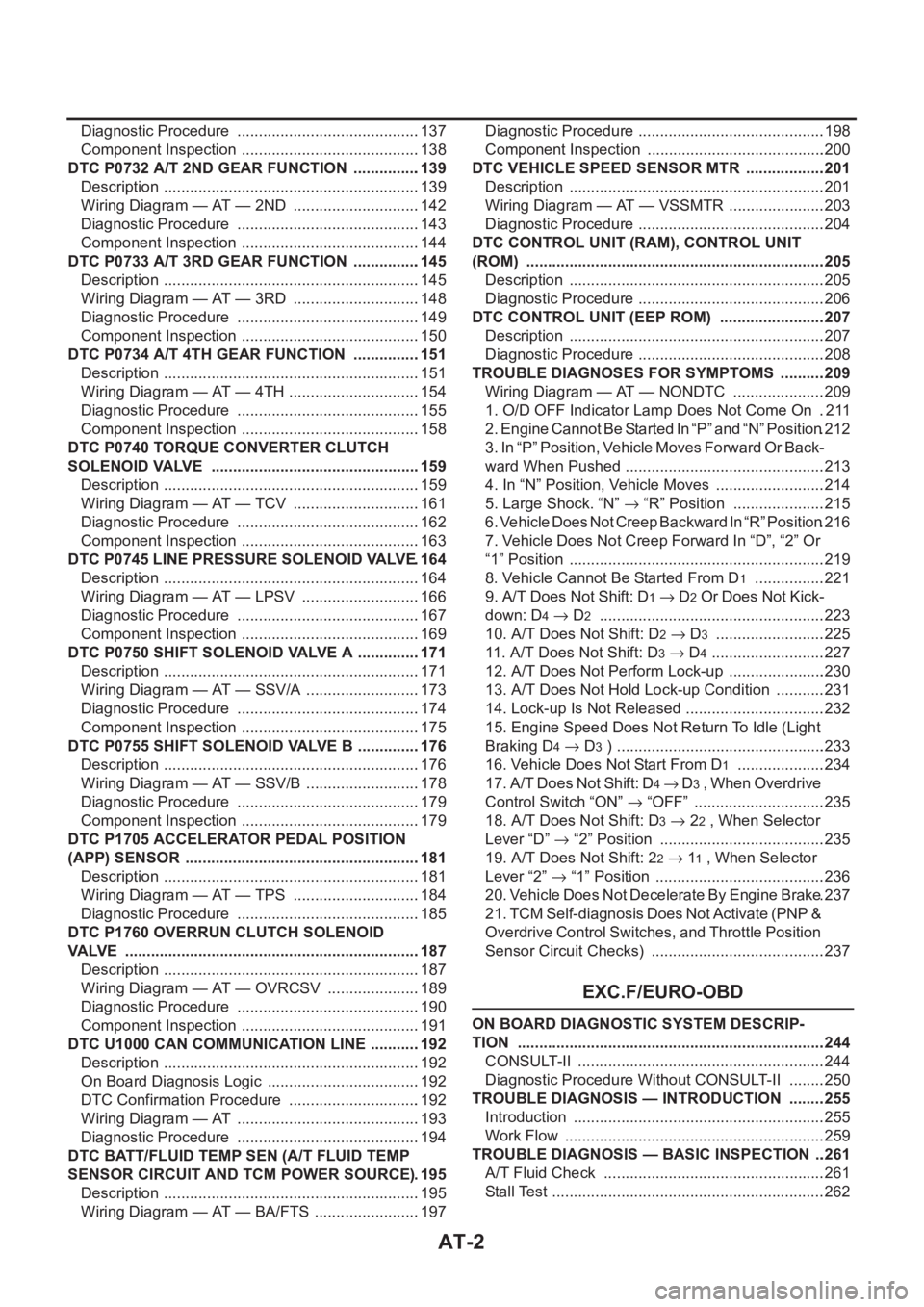
Wiring Diagram — AT — BA/FTS .........................197Diagnostic Procedure ............................................198
Component Inspection ..........................................200
DTC VEHICLE SPEED SENSOR MTR ...................201
Description ............................................................201
Wiring Diagram — AT — VSSMTR .......................203
Diagnostic Procedure ............................................204
DTC CONTROL UNIT (RAM), CONTROL UNIT
(ROM) ......................................................................205
Description ............................................................205
Diagnostic Procedure ............................................206
DTC CONTROL UNIT (EEP ROM) .........................207
Description ............................................................207
Diagnostic Procedure ............................................208
TROUBLE DIAGNOSES FOR SYMPTOMS ...........209
Wiring Diagram — AT — NONDTC ......................209
1. O/D OFF Indicator Lamp Does Not Come On ..211
2. Engine Cannot Be Started In “P” and “N” Position .212
3. In “P” Position, Vehicle Moves Forward Or Back-
ward When Pushed ...............................................213
4. In “N” Position, Vehicle Moves ..........................214
5. Large Shock. “N” → “R” Position ......................215
6. Vehicle Does Not Creep Backward In “R” Position .216
7. Vehicle Does Not Creep Forward In “D”, “2” Or
“1” Position ............................................................219
8. Vehicle Cannot Be Started From D
1 .................221
9. A/T Does Not Shift: D
1→ D2 Or Does Not Kick-
down: D
4→ D2 .....................................................223
10. A/T Does Not Shift: D
2→ D3 ..........................225
11. A/T Does Not Shift: D
3→ D4 ...........................227
12. A/T Does Not Perform Lock-up .......................230
13. A/T Does Not Hold Lock-up Condition ............231
14. Lock-up Is Not Released .................................232
15. Engine Speed Does Not Return To Idle (Light
Braking D
4→ D3 ) .................................................233
16. Vehicle Does Not Start From D
1 .....................234
17. A/T Does Not Shift: D
4→ D3 , W h e n O v e r d r i v e
Control Switch “ON” → “OFF” ...............................235
18. A/T Does Not Shift: D
3→ 22 , When Selector
Lever “D” → “2” Position .......................................235
19. A/T Does Not Shift: 2
2→ 11 , When Selector
Lever “2” → “1” Position ........................................236
20. Vehicle Does Not Decelerate By Engine Brake .237
21. TCM Self-diagnosis Does Not Activate (PNP &
Overdrive Control Switches, and Throttle Position
Sensor Circuit Checks) .........................................237
EXC.F/EURO-OBD
ON BOARD DIAGNOSTIC SYSTEM DESCRIP-
TION ........................................................................244
CONSULT-II ..........................................................244
Diagnostic Procedure Without CONSULT-II .........250
TROUBLE DIAGNOSIS — INTRODUCTION .........255
Introduction ...........................................................255
Work Flow .............................................................259
TROUBLE DIAGNOSIS — BASIC INSPECTION ...261
A/T Fluid Check ....................................................261
Stall Test ................................................................262
Page 1459 of 3189
AT-3
D
E
F
G
H
I
J
K
L
MA
B
AT Line Pressure Test ............................................... 265
Road Test ............................................................. 266
TROUBLE DIAGNOSIS — GENERAL DESCRIP-
TION ........................................................................ 283
Symptom Chart .................................................... 283
TCM Terminals and Reference Value ................... 302
CAN COMMUNICATION ........................................ 305
System Description .............................................. 305
CAN Communication Unit .................................... 305
TROUBLE DIAGNOSES FOR SYMPTOMS .......... 307
Wiring Diagram — AT — NONDTC ...................... 307
1. O/D OFF Indicator Lamp Does Not Come On . 309
2. Engine Cannot Be Started In “P” and “N” Position . 309
3. In “P” Position, Vehicle Moves Forward Or Back-
ward When Pushed .............................................. 310
4. In “N” Position, Vehicle Moves .......................... 311
5. Large Shock. “N” → “R” Position ...................... 312
6. Vehicle Does Not Creep Backward In “R” Position . 313
7. Vehicle Does Not Creep Forward In “D”, “2” Or
“1” Position ........................................................... 316
8. Vehicle Cannot Be Started From D
1 ................. 317
9. A/T Does Not Shift: D
1→ D2 Or Does Not Kick
down: D
4→ D2 ..................................................... 320
10. A/T Does Not Shift: D
2→ D3 ......................... 322
11. A/T Does Not Shift: D
3→ D4 .......................... 324
12. A/T Does Not Perform Lock-up ...................... 326
13. A/T Does Not Hold Lock-up Condition ........... 326
14. Lock-up Is Not Released ................................ 328
15. Engine Speed Does Not Return To Idle (Light
Braking D
4→ D3 ) ................................................ 328
16. Vehicle Does Not Start From D
1 ..................... 330
17. A/T Does Not Shift: D
4→ D3 , When Overdrive
Control Switch “ON” → “OFF” .............................. 330
18. A/T Does Not Shift: D
3→ 22 , When Selector
Lever “D” → “2” Position ...................................... 331
19. A/T Does Not Shift: 2
2→ 11 , When Selector
Lever “2” → “1” Position ....................................... 332
20. Vehicle Does Not Decelerate By Engine Brake . 333
21. TCM Self-diagnosis Does Not Activate (PNP &
Overdrive Control Switches, and Throttle Position
Sensor Circuit Checks) ........................................ 333
ALL
MAIN POWER SUPPLY AND GROUND CIRCUIT . 340
Wiring Diagram — AT — MAIN ............................ 340
Diagnostic Procedure ........................................... 341
VEHICLE SPEED SENSOR - A/T (REVOLUTION
SENSOR) ................................................................ 343
Description ........................................................... 343
Wiring Diagram — AT — VSSAT ......................... 345
Diagnostic Procedure ........................................... 346
DTC VEHICLE SPEED SENSOR MTR .................. 348
Description ........................................................... 348
Wiring Diagram — AT — VSSMTR ...................... 350
Diagnostic Procedure ........................................... 351
ACCELE RATOR PEDAL POSITION (APP) SEN-
SOR ........................................................................ 352
Description ........................................................... 352Wiring Diagram — AT — TPS ..............................354
Diagnostic Procedure ...........................................355
SHIFT SOLENOID VALVE A ..................................357
Description ............................................................357
Wiring Diagram — AT — SSV/A ...........................359
Diagnostic Procedure ...........................................360
Component Inspection ..........................................360
SHIFT SOLENOID VALVE B ..................................362
Description ............................................................362
Wiring Diagram — AT — SSV/B ...........................364
Diagnostic Procedure ...........................................365
Component Inspection ..........................................365
OVERRUN CLUTCH SOLENOID VALVE ...............367
Description ............................................................367
Wiring Diagram — AT — OVRCSV ......................369
Diagnostic Procedure ...........................................370
Component Inspection ..........................................371
TORQUE CONVERTER CLUTCH SOLENOID
VALVE .....................................................................372
Description ............................................................372
Wiring Diagram — AT — TCV ..............................374
Diagnostic Procedure ...........................................375
Component Inspection ..........................................375
BATT/FLUID TEMP SEN (A/T FLUID TEMP SEN-
SOR CIRCUIT AND TCM POWER SOURCE) .......377
Description ............................................................377
Wiring Diagram — AT — BA/FTS .........................379
Diagnostic Procedure ...........................................380
Component Inspection ..........................................382
ENGINE SPEED SIGNAL .......................................383
Description ............................................................383
Wiring Diagram — AT — ENGSS .........................385
Diagnostic Procedure ...........................................386
LINE PRESSURE SOLENOID VALVE ...................388
Description ............................................................388
Wiring Diagram — AT — LPSV ............................390
Diagnostic Procedure ...........................................391
Component Inspection ..........................................393
CAN COMMUNICATION LINE ...............................395
Description ............................................................395
On Board Diagnosis Logic ....................................395
Self-Diagnosis Code Confirmation Procedure ......395
Wiring Diagram — AT — CAN ..............................396
Diagnostic Procedure ...........................................397
A/T SHIFT LOCK SYSTEM ....................................398
Description ............................................................398
Shift Lock System Electrical Parts Location .........398
Wiring Diagram — SHIFT — ................................399
Diagnostic Procedure ...........................................400
KEY INTERLOCK CABLE ......................................404
Components .........................................................404
Removal ...............................................................404
Installation ............................................................405
ON-VEHICLE SERVICE ..........................................406
Control Valve Assembly and Accumulators ..........406
Control Cable Adjustment .....................................408
Park/Neutral Position (PNP) Switch Adjustment ..408
Differential Side Oil Seal Replacement ................409
Revolution Sensor Replacement ..........................409
Page 1486 of 3189
AT-30
OVERALL SYSTEM
SHIFT CONTROL
The shift is regulated entirely by electronic control to accommodate vehicle speed and varying engine opera-
tions. This is accomplished by electrical signals transmitted by the revolution sensor and throttle position sen-
sor. This results in improved acceleration performance and fuel economy.
Control of Shift Solenoid Valves A and B
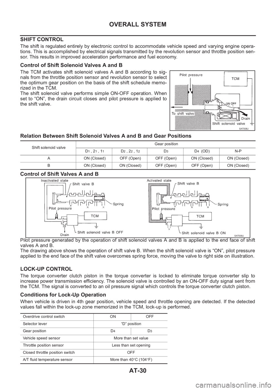
The TCM activates shift solenoid valves A and B according to sig-
nals from the throttle position sensor and revolution sensor to select
the optimum gear position on the basis of the shift schedule memo-
rized in the TCM.
The shift solenoid valve performs simple ON-OFF operation. When
set to “ON”, the drain circuit closes and pilot pressure is applied to
the shift valve.
Relation Between Shift Solenoid Valves A and B and Gear Positions
Control of Shift Valves A and B
Pilot pressure generated by the operation of shift solenoid valves A and B is applied to the end face of shift
valves A and B.
The drawing above shows the operation of shift valve B. When the shift solenoid valve is “ON”, pilot pressure
applied to the end face of the shift valve overcomes spring force, moving the valve to right side on illustration.
LOCK-UP CONTROL
The torque converter clutch piston in the torque converter is locked to eliminate torque converter slip to
increase power transmission efficiency. The solenoid valve is controlled by an ON-OFF duty signal sent from
the TCM. The signal is converted to an oil pressure signal which controls the torque converter clutch piston.
Conditions for Lock-Up Operation
When vehicle is driven in 4th gear position, vehicle speed and throttle opening are detected. If the detected
values fall within the lock-up zone memorized in the TCM, lock-up is performed.
SAT008J
Shift solenoid valveGear position
D1 , 21 , 11D2 , 22 , 12D3D4 (OD) N-P
A ON (Closed) OFF (Open) OFF (Open) ON (Closed) ON (Closed)
B ON (Closed) ON (Closed) OFF (Open) OFF (Open) ON (Closed)
SAT009J
Overdrive control switch ON OFF
Selector lever “D” position
Gear position D
4D3
Vehicle speed sensor More than set value
Throttle position sensor Less than set opening
Closed throttle position switch OFF
A/T fluid temperature sensor More than 40°C (104°F)
Page 1490 of 3189
AT-34
OVERALL SYSTEM
Control Valve
ECS007NL
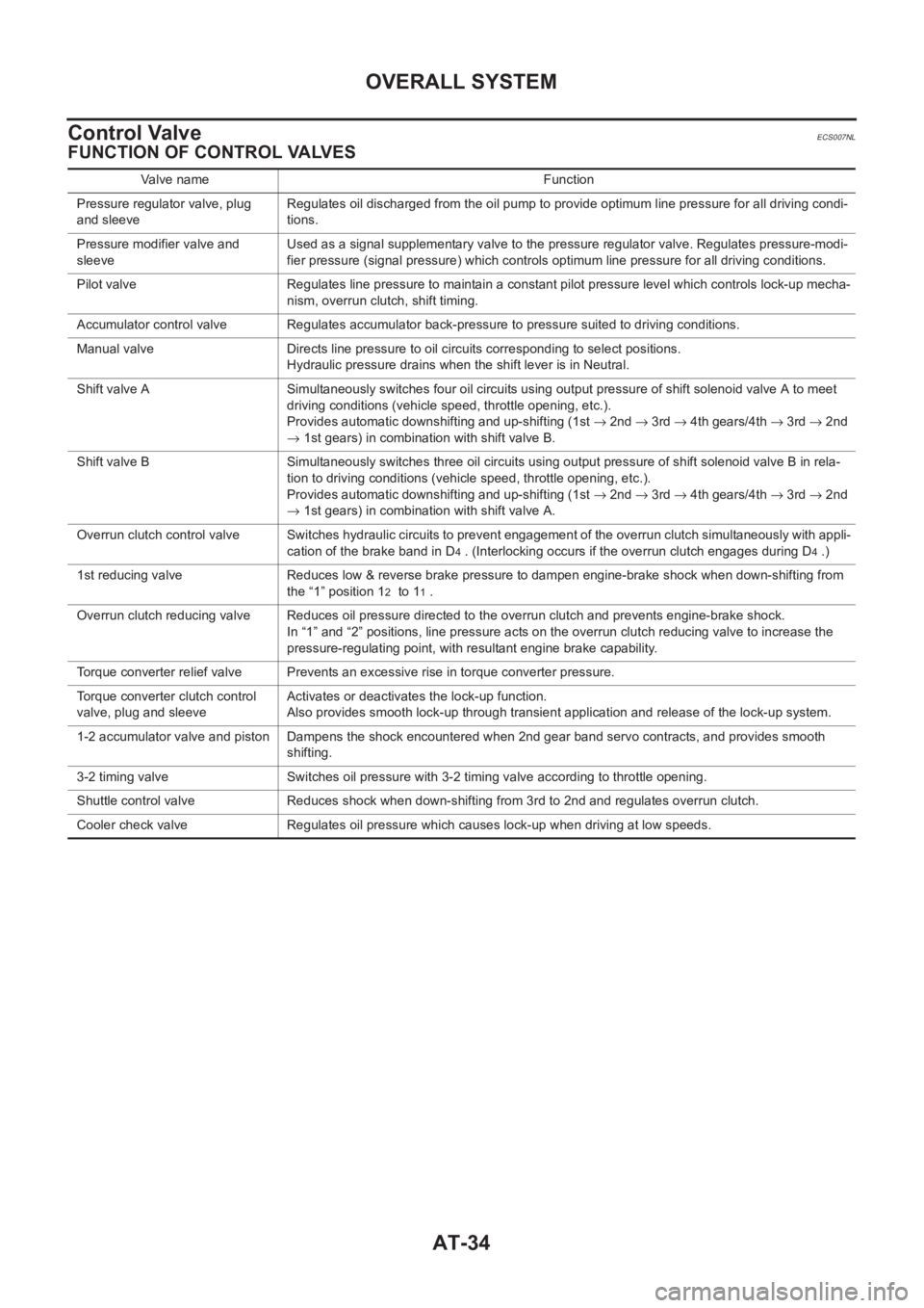
FUNCTION OF CONTROL VALVES
Valve name Function
Pressure regulator valve, plug
and sleeveRegulates oil discharged from the oil pump to provide optimum line pressure for all driving condi-
tions.
Pressure modifier valve and
sleeveUsed as a signal supplementary valve to the pressure regulator valve. Regulates pressure-modi-
fier pressure (signal pressure) which controls optimum line pressure for all driving conditions.
Pilot valve Regulates line pressure to maintain a constant pilot pressure level which controls lock-up mecha-
nism, overrun clutch, shift timing.
Accumulator control valve Regulates accumulator back-pressure to pressure suited to driving conditions.
Manual valve Directs line pressure to oil circuits corresponding to select positions.
Hydraulic pressure drains when the shift lever is in Neutral.
Shift valve A Simultaneously switches four oil circuits using output pressure of shift solenoid valve A to meet
driving conditions (vehicle speed, throttle opening, etc.).
Provides automatic downshifting and up-shifting (1st → 2nd → 3rd → 4th gears/4th → 3rd → 2nd
→ 1st gears) in combination with shift valve B.
Shift valve B Simultaneously switches three oil circuits using output pressure of shift solenoid valve B in rela-
tion to driving conditions (vehicle speed, throttle opening, etc.).
Provides automatic downshifting and up-shifting (1st → 2nd → 3rd → 4th gears/4th → 3rd → 2nd
→ 1st gears) in combination with shift valve A.
Overrun clutch control valve Switches hydraulic circuits to prevent engagement of the overrun clutch simultaneously with appli-
cation of the brake band in D
4 . (Interlocking occurs if the overrun clutch engages during D4 .)
1st reducing valve Reduces low & reverse brake pressure to dampen engine-brake shock when down-shifting from
the “1” position 1
2 to 11 .
Overrun clutch reducing valve Reduces oil pressure directed to the overrun clutch and prevents engine-brake shock.
In “1” and “2” positions, line pressure acts on the overrun clutch reducing valve to increase the
pressure-regulating point, with resultant engine brake capability.
Torque converter relief valve Prevents an excessive rise in torque converter pressure.
Torque converter clutch control
valve, plug and sleeveActivates or deactivates the lock-up function.
Also provides smooth lock-up through transient application and release of the lock-up system.
1-2 accumulator valve and piston Dampens the shock encountered when 2nd gear band servo contracts, and provides smooth
shifting.
3-2 timing valve Switches oil pressure with 3-2 timing valve according to throttle opening.
Shuttle control valve Reduces shock when down-shifting from 3rd to 2nd and regulates overrun clutch.
Cooler check valve Regulates oil pressure which causes lock-up when driving at low speeds.
Page 1501 of 3189
![NISSAN ALMERA N16 2003 Electronic Repair Manual ON BOARD DIAGNOSTIC SYSTEM DESCRIPTION
AT-45
[EURO-OBD]
D
E
F
G
H
I
J
K
L
MA
B
AT
Vehicle speed VEHICLE
SPEED
[km/h] or [mph]—— X●Vehicle speed data,
used for computation
by TCM, is displayed NISSAN ALMERA N16 2003 Electronic Repair Manual ON BOARD DIAGNOSTIC SYSTEM DESCRIPTION
AT-45
[EURO-OBD]
D
E
F
G
H
I
J
K
L
MA
B
AT
Vehicle speed VEHICLE
SPEED
[km/h] or [mph]—— X●Vehicle speed data,
used for computation
by TCM, is displayed](/manual-img/5/57350/w960_57350-1500.png)
ON BOARD DIAGNOSTIC SYSTEM DESCRIPTION
AT-45
[EURO-OBD]
D
E
F
G
H
I
J
K
L
MA
B
AT
Vehicle speed VEHICLE
SPEED
[km/h] or [mph]—— X●Vehicle speed data,
used for computation
by TCM, is displayed.
Torque converter
slip ratioTC SLIP
RATIO
[0.000]———
●Ratio of engine revolu-
tion to input shaft revo-
lution of torque
converter
Torque converter
slip speedTC SLIP
SPEED
[rpm]———Difference in revolution
between input shaft revo-
lution and input shaft rev-
olution of torque
converterDisplay doesn't indicate
o rpm even if engine is
stopped.
But this isn't malfunc-
tion.
can communica-
tionCAN COMM
[OK/UNKWN]—X—
CAN circuit 1CAN CIRC 1
[OK/UNKWN]—X—
CAN circuit 2CAN CIRC 2
[OK/UNKWN]—X—
CAN circuit 3CAN CIRC 3
[OK/UNKWN]—X—
CAN circuit 4CAN CIRC 4
[OK/UNKWN]—X—
CAN circuit 5CAN CIRC 5
[OK/UNKWN]—X—
Throttle position THROTTLE
POSI
[/8]—— X
●Throttle position data,
used for computation
by TCM, is displayed.●A specific value used
for control is displayed
if fail-safe is activated
due to error.
Stop lamp switch BRAKE SW
[ON/OFF]
X——
●ON/OFF status is dis-
played.
ON... Brake pedal is
depressed.
OFF... Brake pedal is
released.
Line pressure duty LINE PRES DTY
[%]
—— X
●Control value of line
pressure solenoid
valve, computed by
TCM from each input
signal, is displayed.
Torque converter
clutch solenoid
valve dutyTCC S/V DUTY
[%]
—— X
●Control value of torque
converter clutch sole-
noid valve, computed
by TCM from each
input signal, is dis-
played. Item DisplayMover to center Monitor items
Description Remarks TCM
Input
signalsCAN
comm
sig-
nalsMain
signalsSelection
from
menu