2003 NISSAN ALMERA N16 Timing
[x] Cancel search: TimingPage 1081 of 3189
JEF356Y
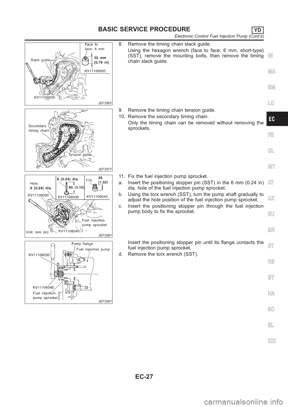
8. Remove the timing chain slack guide.
Using the hexagon wrench (face to face: 6 mm, short-type)
(SST), remove the mounting bolts, then remove the timing
chain slack guide.
JEF357Y
9. Remove the timing chain tension guide.
10. Remove the secondary timing chain.
Only the timing chain can be removed without removing the
sprockets.
JEF358Y
11. Fix the fuel injection pump sprocket.
a. Insert the positioning stopper pin (SST) in the 6 mm (0.24 in)
dia. hole of the fuel injection pump sprocket.
b. Using the torx wrench (SST), turn the pump shaft gradually to
adjust the hole position of the fuel injection pump sprocket.
c. Insert the positioning stopper pin through the fuel injection
pump body to fix the sprocket.
JEF359Y
Insert the positioning stopper pin until its flange contacts the
fuel injection pump sprocket.
d. Remove the torx wrench (SST).
GI
MA
EM
LC
FE
CL
MT
AT
AX
SU
BR
ST
RS
BT
HA
SC
EL
IDX
BASIC SERVICE PROCEDUREYD
Electronic Control Fuel Injection Pump (Cont’d)
EC-27
Page 1083 of 3189
JEF365Y
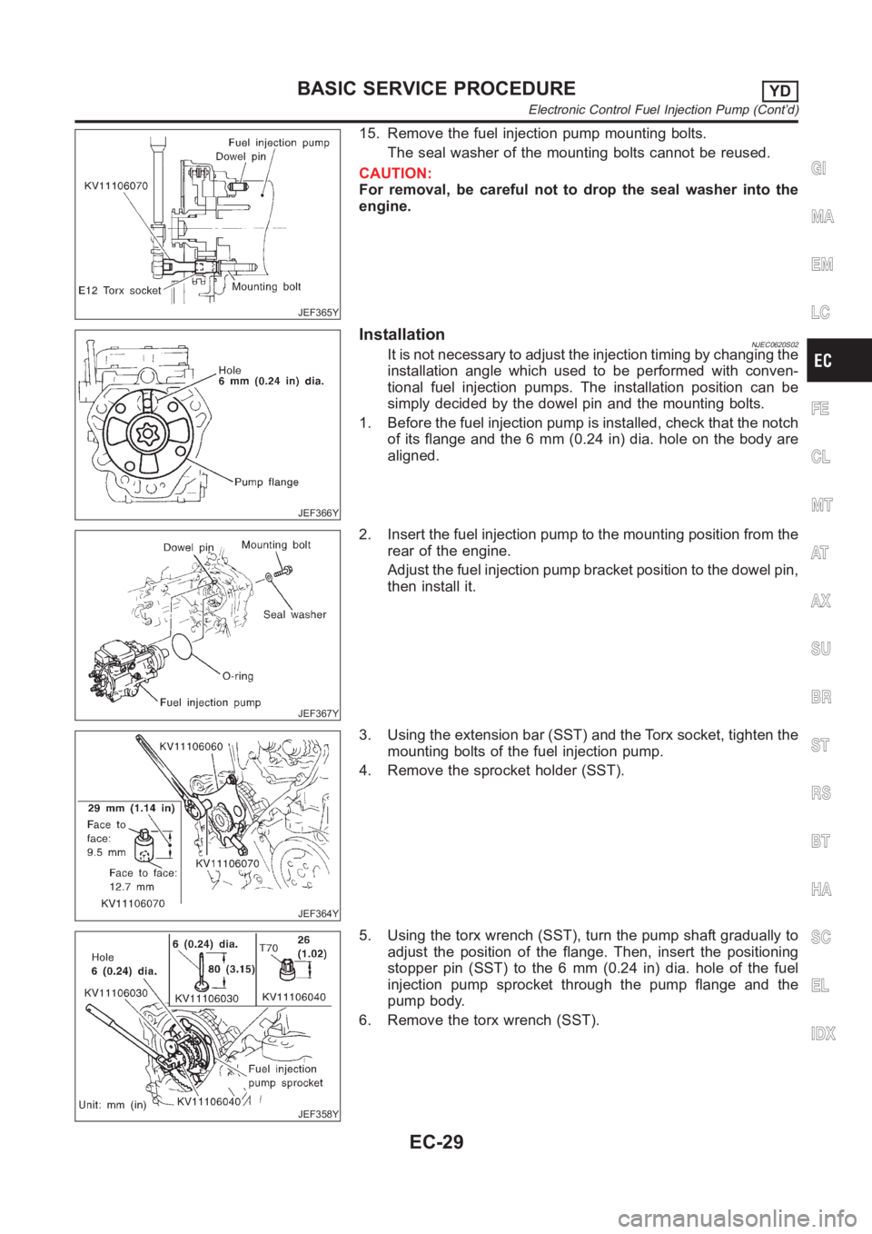
15. Remove the fuel injection pump mounting bolts.
The seal washer of the mounting bolts cannot be reused.
CAUTION:
For removal, be careful not to drop the seal washer into the
engine.
JEF366Y
InstallationNJEC0620S02It is not necessary to adjust the injection timing by changing the
installation angle which used to be performed with conven-
tional fuel injection pumps. The installation position can be
simply decided by the dowel pin and the mounting bolts.
1. Before the fuel injection pump is installed, check that the notch
of its flange and the 6 mm (0.24 in) dia. hole on the body are
aligned.
JEF367Y
2. Insert the fuel injection pump to the mounting position from the
rear of the engine.
Adjust the fuel injection pump bracket position to the dowel pin,
then install it.
JEF364Y
3. Using the extension bar (SST) and the Torx socket, tighten the
mounting bolts of the fuel injection pump.
4. Remove the sprocket holder (SST).
JEF358Y
5. Using the torx wrench (SST), turn the pump shaft gradually to
adjust the position of the flange. Then, insert the positioning
stopper pin (SST) to the 6 mm (0.24 in) dia. hole of the fuel
injection pump sprocket through the pump flange and the
pump body.
6. Remove the torx wrench (SST).
GI
MA
EM
LC
FE
CL
MT
AT
AX
SU
BR
ST
RS
BT
HA
SC
EL
IDX
BASIC SERVICE PROCEDUREYD
Electronic Control Fuel Injection Pump (Cont’d)
EC-29
Page 1084 of 3189
JEF360Y
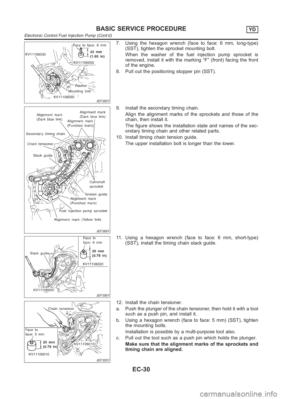
7. Using the hexagon wrench (face to face: 6 mm, long-type)
(SST), tighten the sprocket mounting bolt.
When the washer of the fuel injection pump sprocket is
removed, install it with the marking “F” (front) facing the front
of the engine.
8. Pull out the positioning stopper pin (SST).
JEF368Y
9. Install the secondary timing chain.
Align the alignment marks of the sprockets and those of the
chain, then install it.
The figure shows the installation state and names of the sec-
ondary timing chain and other related parts.
10. Install timing chain tension guide.
The upper installation bolt is longer than the lower.
JEF356Y
11. Using a hexagon wrench (face to face: 6 mm, short-type)
(SST), install the timing chain slack guide.
JEF355Y
12. Install the chain tensioner.
a. Push the plunger of the chain tensioner, then hold it with a tool
such as a push pin, and install it.
b. Using a hexagon wrench (face to face: 5 mm) (SST), tighten
the mounting bolts.
Installation is possible by a multi-purpose tool also.
c. Pull out the tool such as a push pin which holds the plunger.
Make sure that the alignment marks of the sprockets and
timing chain are aligned.
BASIC SERVICE PROCEDUREYD
Electronic Control Fuel Injection Pump (Cont’d)
EC-30
Page 1098 of 3189
SEF858S
Introduction
SEF233G
SEF234G
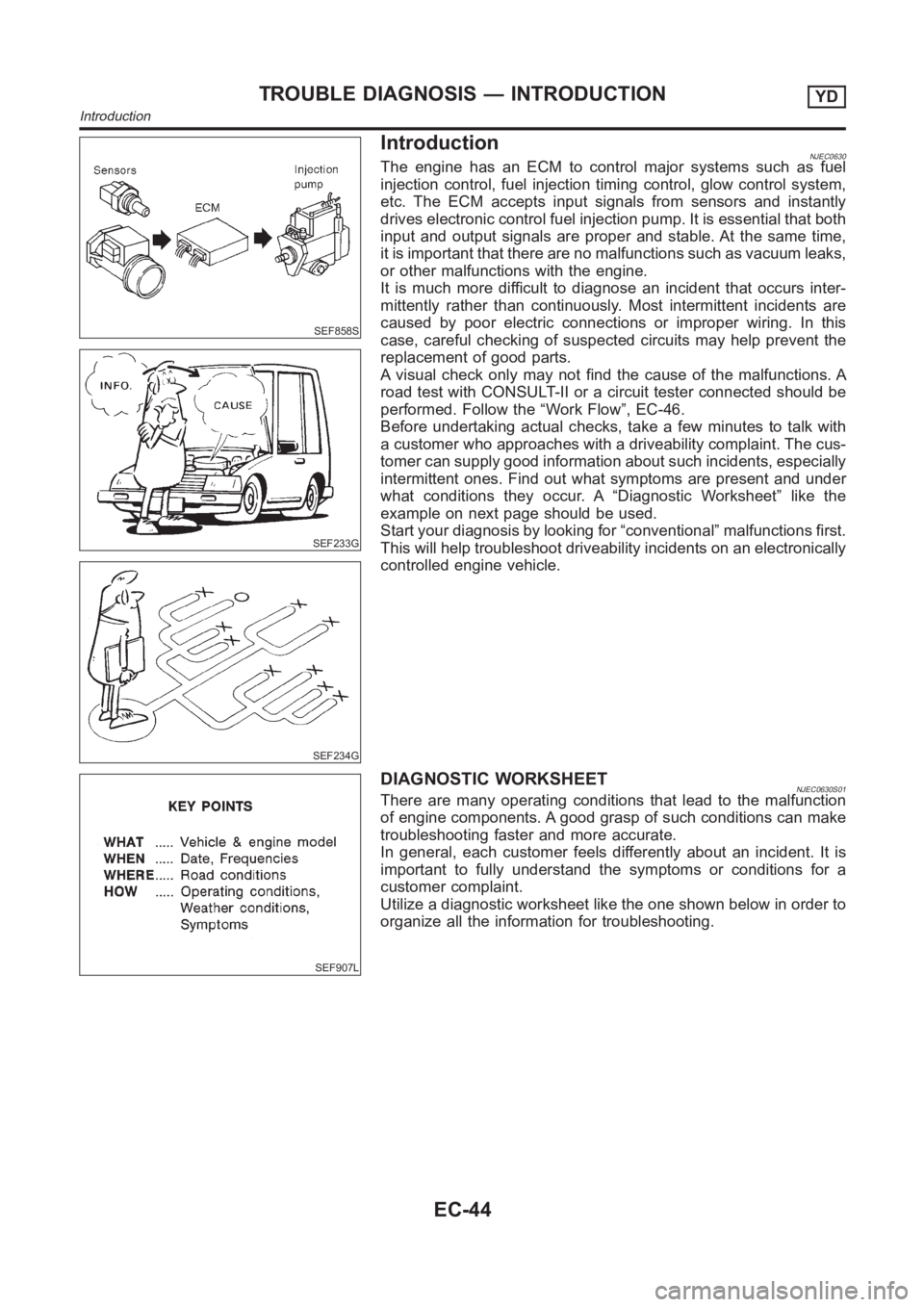
NJEC0630The engine has an ECM to control major systems such as fuel
injection control, fuel injection timing control, glow control system,
etc. The ECM accepts input signals from sensors and instantly
drives electronic control fuel injection pump. It is essential that both
input and output signals are proper and stable. At the same time,
it is important that there are no malfunctions such as vacuum leaks,
or other malfunctions with the engine.
It is much more difficult to diagnose an incident that occurs inter-
mittently rather than continuously. Most intermittent incidents are
caused by poor electric connections or improper wiring. In this
case, careful checking of suspected circuits may help prevent the
replacement of good parts.
A visual check only may not find the cause of the malfunctions. A
road test with CONSULT-II or a circuit tester connected should be
performed. Follow the “Work Flow”, EC-46.
Before undertaking actual checks, take a few minutes to talk with
a customer who approaches with a driveability complaint. The cus-
tomer can supply good information about such incidents, especially
intermittent ones. Find out what symptoms are present and under
what conditions they occur. A “Diagnostic Worksheet” like the
example on next page should be used.
Start your diagnosis by looking for “conventional” malfunctions first.
This will help troubleshoot driveability incidents on an electronically
controlled engine vehicle.
SEF907L
DIAGNOSTIC WORKSHEETNJEC0630S01There are many operating conditions that lead to the malfunction
of engine components. A good grasp of such conditions can make
troubleshooting faster and more accurate.
In general, each customer feels differently about an incident. It is
important to fully understand the symptoms or conditions for a
customer complaint.
Utilize a diagnostic worksheet like the one shown below in order to
organize all the information for troubleshooting.
TROUBLE DIAGNOSIS — INTRODUCTIONYD
Introduction
EC-44
Page 1107 of 3189
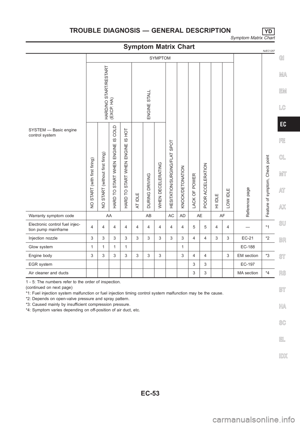
Symptom Matrix ChartNJEC1257
SYSTEM — Basic engine
control systemSYMPTOM
Reference page
Feature of symptom, Check pointHARD/NO START/RESTART
(EXCP. HA)
ENGINE STALL
HESITATION/SURGING/FLAT SPOT
KNOCK/DETONATION
LACK OF POWER
POOR ACCELERATION
HI IDLE
LOW IDLE NO START (with first firing)
NO START (without first firing)
HARD TO START WHEN ENGINE IS COLD
HARD TO START WHEN ENGINE IS HOT
AT IDLE
DURING DRIVING
WHEN DECELERATINGWarranty symptom code AA AB AC AD AE AF
Electronic control fuel injec-
tion pump mainframe4444444445544 — *1
Injection nozzle 3 3 3 3333334433 EC-21 *2
Glow system 1 1 1 1 1 EC-188
Engine body 3 3 3 3 3 3 3 3 4 4 3 EM section *3
EGR system3 3 EC-197
Air cleaner and ducts 3 3 MA section *4
1 - 5: The numbers refer to the order of inspection.
(continued on next page)
*1: Fuel injection system malfunction or fuel injection timing control system malfunction may be the cause.
*2: Depends on open-valve pressure and spray pattern.
*3: Caused mainly by insufficient compression pressure.
*4: Symptom varies depending on off-position of air duct, etc.
GI
MA
EM
LC
FE
CL
MT
AT
AX
SU
BR
ST
RS
BT
HA
SC
EL
IDX
TROUBLE DIAGNOSIS — GENERAL DESCRIPTIONYD
Symptom Matrix Chart
EC-53
Page 1108 of 3189
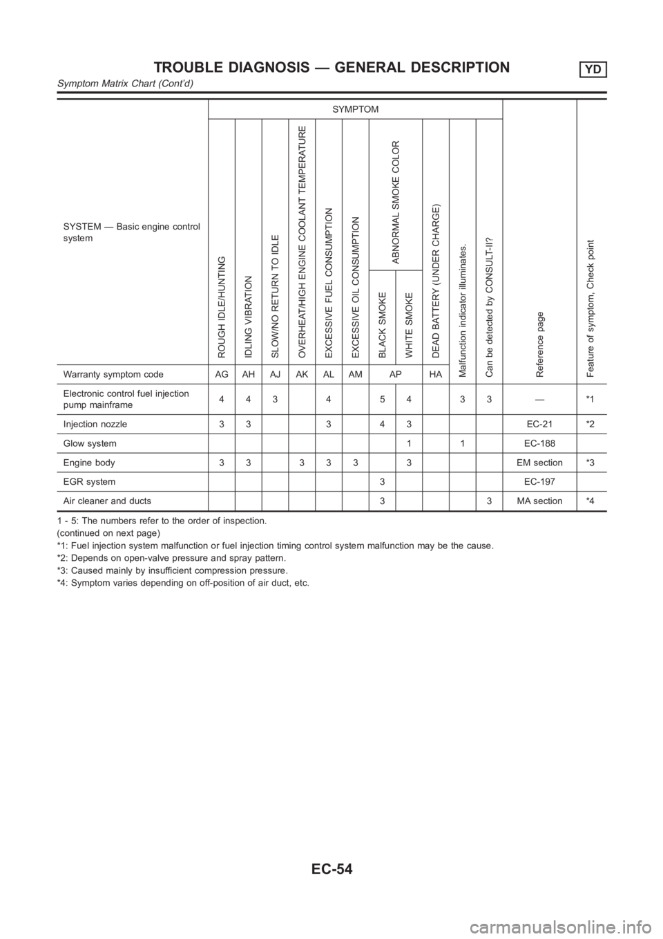
SYSTEM — Basic engine control
systemSYMPTOM
Reference page
Feature of symptom, Check pointROUGH IDLE/HUNTING
IDLING VIBRATION
SLOW/NO RETURN TO IDLE
OVERHEAT/HIGH ENGINE COOLANT TEMPERATURE
EXCESSIVE FUEL CONSUMPTION
EXCESSIVE OIL CONSUMPTION
ABNORMAL SMOKE COLOR
DEAD BATTERY (UNDER CHARGE)
Malfunction indicator illuminates.
Can be detected by CONSULT-II?BLACK SMOKE
WHITE SMOKEWarranty symptom code AG AH AJ AK AL AM AP HA
Electronic control fuel injection
pump mainframe44345433—*1
Injection nozzle 3 3 3 4 3 EC-21 *2
Glow system 1 1 EC-188
Engine body 3 3 3 3 3 3 EM section *3
EGR system 3 EC-197
Air cleaner and ducts 3 3 MA section *4
1 - 5: The numbers refer to the order of inspection.
(continued on next page)
*1: Fuel injection system malfunction or fuel injection timing control system malfunction may be the cause.
*2: Depends on open-valve pressure and spray pattern.
*3: Caused mainly by insufficient compression pressure.
*4: Symptom varies depending on off-position of air duct, etc.
TROUBLE DIAGNOSIS — GENERAL DESCRIPTIONYD
Symptom Matrix Chart (Cont’d)
EC-54
Page 1153 of 3189
SEF420Z
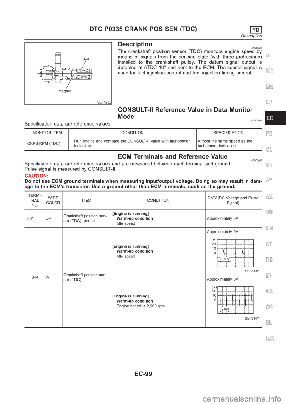
DescriptionNJEC0686The crankshaft position sensor (TDC) monitors engine speed by
means of signals from the sensing plate (with three protrusions)
installed to the crankshaft pulley. The datum signal output is
detected at ATDC 10° and sent to the ECM. The sensor signal is
used for fuel injection control and fuel injection timing control.
CONSULT-II Reference Value in Data Monitor
Mode
NJEC0687Specification data are reference values.
MONITOR ITEM CONDITION SPECIFICATION
CKPS·RPM (TDC)Run engine and compare the CONSULT-II value with tachometer
indication.Almost the same speed as the
tachometer indication.
ECM Terminals and Reference ValueNJEC0688Specification data are reference values and are measured between each terminal and ground.
Pulse signal is measured by CONSULT-II.
CAUTION:
Do not use ECM ground terminals when measuring input/output voltage. Doing so may result in dam-
age to the ECM’s transistor. Use a ground other than ECM terminals, such as the ground.
TERMI-
NAL
NO.WIRE
COLORITEM CONDITIONDATA(DC Voltage and Pulse
Signal)
331 ORCrankshaft position sen-
sor (TDC) ground[Engine is running]
Warm-up condition
Idle speedApproximately 0V
344 WCrankshaft position sen-
sor (TDC)[Engine is running]
Warm-up condition
Idle speedApproximately 0V
SEF333Y
[Engine is running]
Warm-up condition
Engine speed is 2,000 rpmApproximately 0V
SEF334Y
GI
MA
EM
LC
FE
CL
MT
AT
AX
SU
BR
ST
RS
BT
HA
SC
EL
IDX
DTC P0335 CRANK POS SEN (TDC)YD
Description
EC-99
Page 1172 of 3189
SEF437Y
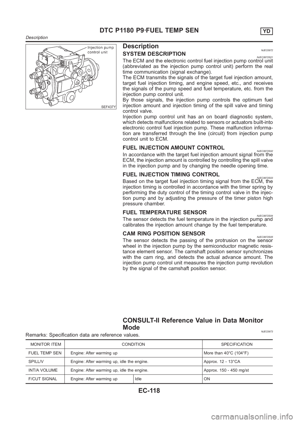
DescriptionNJEC0672SYSTEM DESCRIPTIONNJEC0672S01The ECM and the electronic control fuel injection pump control unit
(abbreviated as the injection pump control unit) perform the real
time communication (signal exchange).
The ECM transmits the signals of the target fuel injection amount,
target fuel injection timing, and engine speed, etc., and receives
the signals of the pump speed and fuel temperature, etc. from the
injection pump control unit.
By those signals, the injection pump controls the optimum fuel
injection amount and injection timing of the spill valve and timing
control valve.
Injection pump control unit has an on board diagnostic system,
which detects malfunctions related to sensors or actuators built-into
electronic control fuel injection pump. These malfunction informa-
tion are transferred through the line (circuit) from injection pump
control unit to ECM.
FUEL INJECTION AMOUNT CONTROLNJEC0672S02In accordance with the target fuel injection amount signal from the
ECM, the injection amount is controlled by controlling the spill valve
in the injection pump and by changing the needle opening time.
FUEL INJECTION TIMING CONTROLNJEC0672S03Based on the target fuel injection timing signal from the ECM, the
injection timing is controlled in accordance with the timer spring by
performing the duty control of the timing control valve in the injec-
tion pump and by adjusting the pressure of the timer piston high
pressure chamber.
FUEL TEMPERATURE SENSORNJEC0672S04The sensor detects the fuel temperature in the injection pump and
calibrates the injection amount change by the fuel temperature.
CAM RING POSITION SENSORNJEC0672S05The sensor detects the passing of the protrusion on the sensor
wheel in the injection pump by the semiconductor magnetic resis-
tance element sensor. The camshaft position sensor synchronizes
with the cam ring, and detects the actual advance amount. The
injection pump control unit measures the injection pump revolution
by the signal of the camshaft position sensor.
CONSULT-II Reference Value in Data Monitor
Mode
NJEC0673Remarks: Specification data are reference values.
MONITOR ITEM CONDITION SPECIFICATION
FUEL TEMP SEN Engine: After warming up More than 40°C (104°F)
SPILL/V Engine: After warming up, idle the engine. Approx. 12 - 13°CA
INT/A VOLUME Engine: After warming up, idle the engine. Approx. 150 - 450 mg/st
F/CUT SIGNAL Engine: After warming up Idle ON
DTC P1180 P9·FUEL TEMP SENYD
Description
EC-118