2003 NISSAN ALMERA N16 Timing
[x] Cancel search: TimingPage 1483 of 3189

OVERALL SYSTEM
AT-27
D
E
F
G
H
I
J
K
L
MA
B
AT
Control SystemECS007NJ
OUTLINE
The automatic transaxle senses vehicle operating conditions through various switches and sensors. It always
controls the optimum shift position and reduces shifting and lock-up shocks.
*: This sensor means Accelerator pedal position (APP) sensor.
CONTROL SYSTEM
SWITCHES & SENSORS TCM ACTUATORS
PNP switch
Throttle position sensor*
Engine speed signal
A/T fluid temperature sensor
Revolution sensor
Vehicle speed sensor
Overdrive control switch
Stop lamp switchShift control
Line pressure control
Lock-up control
Overrun clutch control
Timing control
Fail-safe control
Self-diagnosis
CONSULT-II communication line
controlShift solenoid valve A
Shift solenoid valve B
Overrun clutch solenoid valve
Torque converter clutch solenoid
valve
Line pressure solenoid valve
O/D OFF indicator lamp
SCIA0690E
Page 1490 of 3189

AT-34
OVERALL SYSTEM
Control Valve
ECS007NL
FUNCTION OF CONTROL VALVES
Valve name Function
Pressure regulator valve, plug
and sleeveRegulates oil discharged from the oil pump to provide optimum line pressure for all driving condi-
tions.
Pressure modifier valve and
sleeveUsed as a signal supplementary valve to the pressure regulator valve. Regulates pressure-modi-
fier pressure (signal pressure) which controls optimum line pressure for all driving conditions.
Pilot valve Regulates line pressure to maintain a constant pilot pressure level which controls lock-up mecha-
nism, overrun clutch, shift timing.
Accumulator control valve Regulates accumulator back-pressure to pressure suited to driving conditions.
Manual valve Directs line pressure to oil circuits corresponding to select positions.
Hydraulic pressure drains when the shift lever is in Neutral.
Shift valve A Simultaneously switches four oil circuits using output pressure of shift solenoid valve A to meet
driving conditions (vehicle speed, throttle opening, etc.).
Provides automatic downshifting and up-shifting (1st → 2nd → 3rd → 4th gears/4th → 3rd → 2nd
→ 1st gears) in combination with shift valve B.
Shift valve B Simultaneously switches three oil circuits using output pressure of shift solenoid valve B in rela-
tion to driving conditions (vehicle speed, throttle opening, etc.).
Provides automatic downshifting and up-shifting (1st → 2nd → 3rd → 4th gears/4th → 3rd → 2nd
→ 1st gears) in combination with shift valve A.
Overrun clutch control valve Switches hydraulic circuits to prevent engagement of the overrun clutch simultaneously with appli-
cation of the brake band in D
4 . (Interlocking occurs if the overrun clutch engages during D4 .)
1st reducing valve Reduces low & reverse brake pressure to dampen engine-brake shock when down-shifting from
the “1” position 1
2 to 11 .
Overrun clutch reducing valve Reduces oil pressure directed to the overrun clutch and prevents engine-brake shock.
In “1” and “2” positions, line pressure acts on the overrun clutch reducing valve to increase the
pressure-regulating point, with resultant engine brake capability.
Torque converter relief valve Prevents an excessive rise in torque converter pressure.
Torque converter clutch control
valve, plug and sleeveActivates or deactivates the lock-up function.
Also provides smooth lock-up through transient application and release of the lock-up system.
1-2 accumulator valve and piston Dampens the shock encountered when 2nd gear band servo contracts, and provides smooth
shifting.
3-2 timing valve Switches oil pressure with 3-2 timing valve according to throttle opening.
Shuttle control valve Reduces shock when down-shifting from 3rd to 2nd and regulates overrun clutch.
Cooler check valve Regulates oil pressure which causes lock-up when driving at low speeds.
Page 1497 of 3189
![NISSAN ALMERA N16 2003 Electronic Repair Manual ON BOARD DIAGNOSTIC SYSTEM DESCRIPTION
AT-41
[EURO-OBD]
D
E
F
G
H
I
J
K
L
MA
B
AT
Malfunction Indicator (MI)ECS007NR
1. The malfunction indicator lamp will light up when the ignition
switch](/manual-img/5/57350/w960_57350-1496.png "NISSAN ALMERA N16 2003 Electronic Repair Manual ON BOARD DIAGNOSTIC SYSTEM DESCRIPTION
AT-41
[EURO-OBD]
D
E
F
G
H
I
J
K
L
MA
B
AT
Malfunction Indicator (MI)ECS007NR
1. The malfunction indicator lamp will light up when the ignition
switch")
ON BOARD DIAGNOSTIC SYSTEM DESCRIPTION
AT-41
[EURO-OBD]
D
E
F
G
H
I
J
K
L
MA
B
AT
Malfunction Indicator (MI)ECS007NR
1. The malfunction indicator lamp will light up when the ignition
switch is turned ON without the engine running. This is for
checking the lamp.
●If the malfunction indicator does not light up, refer to EC-397
or EC-715 .
(Or see MI & CONSULT-II in EC section. Refer to EC-49
, EC-
87 .
2. When the engine is started, the malfunction indicator should
turned OFF.
If the lamp remains ON, the on board diagnostic system has
detected an emission-related (EURO-OBD) malfunction. For
detail, refer to EC-36.
CONSULT-IIECS007NS
After performing “SELF-DIAGNOSTIC PROCEDURE (WITH CONSULT-II)” AT- 4 1 , place check marks for
results on the “DIAGNOSTIC WORKSHEET”, AT- 5 7
. Reference pages are provided following the items.
NOTICE:
1. The CONSULT-II electrically displays shift timing and lock-up timing (that is, operation timing of each sole-
noid valve).
Check for time difference between actual shift timing and the CONSULT-II display. If the difference is
noticeable, mechanical parts (except solenoid valves, sensors, etc.) may be malfunctioning. Check
mechanical parts using applicable diagnostic procedures.
2. Shift schedule (which implies gear position) displayed on CONSULT-II and that indicated in Service Man-
ual may differ slightly. This occurs because of the following reasons:
–Actual shift schedule has more or less tolerance or allowance,
–Shift schedule indicated in Service Manual refers to the point where shifts start, and
–Gear position displayed on CONSULT-II indicates the point where shifts are completed.
3. Shift solenoid valve “A” or “B” is displayed on CONSULT-II at the start of shifting. Gear position is dis-
played upon completion of shifting (which is computed by TCM).
4. Additional CONSULT-II information can be found in the Operation Manual supplied with the CONSULT-II
unit.
SELF-DIAGNOSTIC PROCEDURE (WITH CONSULT-II)
1. Turn on CONSULT-II and touch “ENGINE” for EURO-OBD
detected items or touch “A/T” for TCM self-diagnosis.
If A/T is not displayed, check TCM power supply and ground cir-
cuit. Refer to AT- 1 0 6 , "
TCM Terminals and Reference Value" . If
result is NG, refer to EL-11, "POWER SUPPLY ROUTING".
2. Touch “SELF DIAGNOSIS”.
Display shows malfunction experienced since the last erasing
operation.
CONSULT-II performs “real time diagnosis”.
Also, any malfunction detected while in this mode will be dis-
played at real time.
SAT652J
SAT014K
SAT987J
Page 1544 of 3189
AT-88
[EURO-OBD]
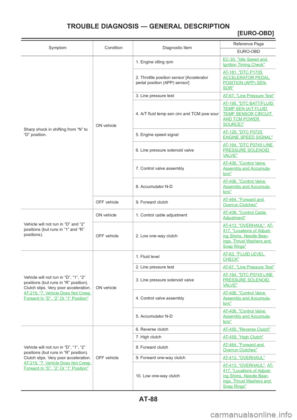
TROUBLE DIAGNOSIS — GENERAL DESCRIPTION
Sharp shock in shifting from “N” to
“D” position.ON vehicle1. Engine idling rpmEC-30, "
Idle Speed and
Ignition Timing Check"
2. Throttle position sensor [Accelerator
pedal position (APP) sensor]AT-181, "
DTC P1705
ACCELERATOR PEDAL
POSITION (APP) SEN-
SOR"
3. Line pressure testAT- 6 7 , "Line Pressure Test"
4. A/T fluid temp sen circ and TCM pow sourAT-195, "
DTC BATT/FLUID
TEMP SEN (A/T FLUID
TEMP SENSOR CIRCUIT
AND TCM POWER
SOURCE)"
5. Engine speed signalAT-129, "DTC P0725
ENGINE SPEED SIGNAL"
6. Line pressure solenoid valveAT-164, "
DTC P0745 LINE
PRESSURE SOLENOID
VA LV E"
7. Control valve assemblyAT-406, "
Control Valve
Assembly and Accumula-
tors"
8. Accumulator N-DAT-406, "
Control Valve
Assembly and Accumula-
tors"
OFF vehicle 9. Forward clutchAT-464, "Forward and
Overrun Clutches"
Vehicle will not run in “D” and “2”
positions (but runs in “1” and “R”
positions).ON vehicle 1. Control cable adjustmentAT-408, "
Control Cable
Adjustment"
OFF vehicle 2. Low one-way clutchAT-413, "
OVERHAUL",AT-
417, "Locations of Adjust-
ing Shims, Needle Bear-
ings, Thrust Washers and
Snap Rings"
Vehicle will not run in “D”, “1”, “2”
positions (but runs in “R” position).
Clutch slips. Very poor acceleration.
AT-219, "
7. Vehicle Does Not Creep
Forward In “D”,“2” Or “1” Position"
ON vehicle1. Fluid levelAT- 6 3 , "
FLUID LEVEL
CHECK"
2. Line pressure testAT- 6 7 , "Line Pressure Test"
3. Line pressure solenoid valveAT-164, "
DTC P0745 LINE
PRESSURE SOLENOID
VA LV E"
4. Control valve assemblyAT-406, "
Control Valve
Assembly and Accumula-
tors"
5. Accumulator N-DAT-406, "
Control Valve
Assembly and Accumula-
tors"
Vehicle will not run in “D”, “1”, “2”
positions (but runs in “R” position).
Clutch slips. Very poor acceleration.
AT-219, "
7. Vehicle Does Not Creep
Forward In “D”,“2” Or “1” Position"
OFF vehicle6. Reverse clutchAT-455, "
Reverse Clutch"
7. High clutchAT-459, "High Clutch"
8. Forward clutchAT-464, "Forward and
Overrun Clutches"
9. Forward one-way clutchAT-413, "OVERHAUL"
10. Low one-way clutchAT-413, "
OVERHAUL",AT-
417, "Locations of Adjust-
ing Shims, Needle Bear-
ings, Thrust Washers and
Snap Rings"
Symptom Condition Diagnostic ItemReference Page
EURO-OBD
Page 1545 of 3189
![NISSAN ALMERA N16 2003 Electronic Repair Manual TROUBLE DIAGNOSIS — GENERAL DESCRIPTION
AT-89
[EURO-OBD]
D
E
F
G
H
I
J
K
L
MA
B
AT
Clutches or brakes slip somewhat in
starting.ON vehicle1. Fluid levelAT-63, "
FLUID LEVEL
CHECK"
2. Contr](/manual-img/5/57350/w960_57350-1544.png "NISSAN ALMERA N16 2003 Electronic Repair Manual TROUBLE DIAGNOSIS — GENERAL DESCRIPTION
AT-89
[EURO-OBD]
D
E
F
G
H
I
J
K
L
MA
B
AT
Clutches or brakes slip somewhat in
starting.ON vehicle1. Fluid levelAT-63, \"
FLUID LEVEL
CHECK\"
2. Contr")
TROUBLE DIAGNOSIS — GENERAL DESCRIPTION
AT-89
[EURO-OBD]
D
E
F
G
H
I
J
K
L
MA
B
AT
Clutches or brakes slip somewhat in
starting.ON vehicle1. Fluid levelAT-63, "
FLUID LEVEL
CHECK"
2. Control cable adjustmentAT-408, "Control Cable
Adjustment"
3. Throttle position sensor [Accelerator
pedal position (APP) sensor]AT-181, "
DTC P1705
ACCELERATOR PEDAL
POSITION (APP) SEN-
SOR"
4. Line pressure testAT-67, "Line Pressure Test"
5. Line pressure solenoid valveAT-164, "
DTC P0745 LINE
PRESSURE SOLENOID
VA LV E"
6. Control valve assemblyAT-406, "
Control Valve
Assembly and Accumula-
tors"
7. Accumulator N-DAT-406, "
Control Valve
Assembly and Accumula-
tors"
OFF vehicle8. Forward clutchAT-464, "
Forward and
Overrun Clutches"
9. Reverse clutchAT-455, "Reverse Clutch"
10. Low & reverse brakeAT-470, "Low & Reverse
Brake"
11. Oil pumpAT-435, "Oil Pump"
12. Torque converterAT-417, "
Locations of
Adjusting Shims, Needle
Bearings, Thrust Washers
and Snap Rings"
Excessive creep. ON vehicle 1. Engine idling rpmEC-30, "Idle Speed and
Ignition Timing Check"
No creep at all.
AT-216, "
6. Vehicle Does Not Creep
Backward In “R” Position" and AT-
219, "7. Vehicle Does Not Creep
Forward In “D”,“2” Or “1” Position"
ON vehicle1. Fluid levelAT-63, "
FLUID LEVEL
CHECK"
2. Line pressure testAT-67, "LINE PRESSURE
TEST PROCEDURE"
3. Control valve assemblyAT-406, "
Control Valve
Assembly and Accumula-
tors"
OFF vehicle4. Forward clutchAT-464, "
Forward and
Overrun Clutches"
5. Oil pumpAT-435, "Oil Pump"
6. Torque converterAT-417, "
Locations of
Adjusting Shims, Needle
Bearings, Thrust Washers
and Snap Rings"
Symptom Condition Diagnostic ItemReference Page
EURO-OBD
Page 1548 of 3189
![NISSAN ALMERA N16 2003 Electronic Repair Manual AT-92
[EURO-OBD]
TROUBLE DIAGNOSIS — GENERAL DESCRIPTION
Engine stops when shifting lever
into “R”, “D”, “2” and “1”.ON vehicle1. Engine idling rpmEC-30, "
Idle Speed and
Ignit](/manual-img/5/57350/w960_57350-1547.png "NISSAN ALMERA N16 2003 Electronic Repair Manual AT-92
[EURO-OBD]
TROUBLE DIAGNOSIS — GENERAL DESCRIPTION
Engine stops when shifting lever
into “R”, “D”, “2” and “1”.ON vehicle1. Engine idling rpmEC-30, \"
Idle Speed and
Ignit")
AT-92
[EURO-OBD]
TROUBLE DIAGNOSIS — GENERAL DESCRIPTION
Engine stops when shifting lever
into “R”, “D”, “2” and “1”.ON vehicle1. Engine idling rpmEC-30, "
Idle Speed and
Ignition Timing Check"
2. Torque converter clutch solenoid valveAT-159, "
DTC P0740
TORQUE CONVERTER
CLUTCH SOLENOID
VA LV E"
3. Control valve assemblyAT-406, "
Control Valve
Assembly and Accumula-
tors"
OFF vehicle 4. Torque converterAT-417, "
Locations of
Adjusting Shims, Needle
Bearings, Thrust Washers
and Snap Rings"
Too sharp a shock in change from
“D
1 ” to “D2 ”.ON vehicle1. Throttle position sensor [Accelerator
pedal position (APP) sensor]AT-181, "
DTC P1705
ACCELERATOR PEDAL
POSITION (APP) SEN-
SOR"
2. Line pressure testAT- 6 7 , "Line Pressure Test"
3. Accumulator servo releaseAT-406, "
Control Valve
Assembly and Accumula-
tors"
4. Control valve assemblyAT-406, "
Control Valve
Assembly and Accumula-
tors"
5. A/T fluid temp sen circ and TCM pow sourAT-195, "
DTC BATT/FLUID
TEMP SEN (A/T FLUID
TEMP SENSOR CIRCUIT
AND TCM POWER
SOURCE)"
OFF vehicle 6. Brake bandAT-483, "Band Servo Pis-
ton Assembly"
Too sharp a shock in change from
“D
2 ” to “D3 ”.ON vehicle1. Throttle position sensor [Accelerator
pedal position (APP) sensor]AT-181, "
DTC P1705
ACCELERATOR PEDAL
POSITION (APP) SEN-
SOR"
2. Line pressure testAT- 6 7 , "Line Pressure Test"
3. Control valve assemblyAT-406, "
Control Valve
Assembly and Accumula-
tors"
OFF vehicle4. High clutchAT-459, "
High Clutch"
5. Brake bandAT-483, "Band Servo Pis-
ton Assembly"
Too sharp a shock in change from
“D
3 ” to “D4 ”.ON vehicle1. Throttle position sensor [Accelerator
pedal position (APP) sensor]AT-181, "
DTC P1705
ACCELERATOR PEDAL
POSITION (APP) SEN-
SOR"
2. Line pressure testAT- 6 7 , "Line Pressure Test"
3. Control valve assemblyAT-406, "
Control Valve
Assembly and Accumula-
tors"
OFF vehicle4. Brake bandAT-483, "
Band Servo Pis-
ton Assembly"
5. Overrun clutchAT-464, "Forward and
Overrun Clutches"
Symptom Condition Diagnostic ItemReference Page
EURO-OBD
Page 1558 of 3189
![NISSAN ALMERA N16 2003 Electronic Repair Manual AT-102
[EURO-OBD]
TROUBLE DIAGNOSIS — GENERAL DESCRIPTION
Large shock changing from “12 ” to
“1
1 ” in “1” position.ON vehicle 1. Control valve assemblyAT-406, "
Control Valve
Asse](/manual-img/5/57350/w960_57350-1557.png "NISSAN ALMERA N16 2003 Electronic Repair Manual AT-102
[EURO-OBD]
TROUBLE DIAGNOSIS — GENERAL DESCRIPTION
Large shock changing from “12 ” to
“1
1 ” in “1” position.ON vehicle 1. Control valve assemblyAT-406, \"
Control Valve
Asse")
AT-102
[EURO-OBD]
TROUBLE DIAGNOSIS — GENERAL DESCRIPTION
Large shock changing from “12 ” to
“1
1 ” in “1” position.ON vehicle 1. Control valve assemblyAT-406, "
Control Valve
Assembly and Accumula-
tors"
OFF vehicle 2. Low & reverse brakeAT-470, "Low & Reverse
Brake"
Transmission overheats.ON vehicle1. Fluid levelAT- 6 3 , "
FLUID LEVEL
CHECK"
2. Engine idling rpmEC-30, "Idle Speed and
Ignition Timing Check"
3. Throttle position sensor [Accelerator
pedal position (APP) sensor]AT-181, "
DTC P1705
ACCELERATOR PEDAL
POSITION (APP) SEN-
SOR"
4. Line pressure testAT- 6 7 , "Line Pressure Test"
5. Line pressure solenoid valveAT-164, "
DTC P0745 LINE
PRESSURE SOLENOID
VA LV E"
6. Control valve assemblyAT-406, "
Control Valve
Assembly and Accumula-
tors"
OFF vehicle7. Oil pumpAT-435, "
Oil Pump"
8. Reverse clutchAT-455, "Reverse Clutch"
9. High clutchAT-459, "High Clutch"
10. Brake bandAT-483, "Band Servo Pis-
ton Assembly"
11. Forward clutchAT-464, "Forward and
Overrun Clutches"
12. Overrun clutchAT-464, "Forward and
Overrun Clutches"
13. Low & reverse brakeAT-470, "Low & Reverse
Brake"
14. Torque converterAT-417, "
Locations of
Adjusting Shims, Needle
Bearings, Thrust Washers
and Snap Rings"
ATF shoots out during operation.
White smoke emitted from exhaust
pipe during operation.ON vehicle 1. Fluid levelAT- 6 3 , "
FLUID LEVEL
CHECK"
OFF vehicle2. Reverse clutchAT-455, "
Reverse Clutch"
3. High clutchAT-459, "High Clutch"
4. Brake bandAT-483, "Band Servo Pis-
ton Assembly"
5. Forward clutchAT-464, "Forward and
Overrun Clutches"
6. Overrun clutchAT-464, "Forward and
Overrun Clutches"
7. Low & reverse brakeAT-470, "Low & Reverse
Brake"
Symptom Condition Diagnostic ItemReference Page
EURO-OBD
Page 1700 of 3189
![NISSAN ALMERA N16 2003 Electronic Repair Manual AT-244
[EXC.F/EURO-OBD]
ON BOARD DIAGNOSTIC SYSTEM DESCRIPTION
[EXC.F/EURO-OBD]ON BOARD DIAGNOSTIC SYSTEM DESCRIPTIONPFP:00000
CONSULT-IIECS007QN
After performing AT- 2 4 4 , "SELF-DIAGNOSTIC](/manual-img/5/57350/w960_57350-1699.png "NISSAN ALMERA N16 2003 Electronic Repair Manual AT-244
[EXC.F/EURO-OBD]
ON BOARD DIAGNOSTIC SYSTEM DESCRIPTION
[EXC.F/EURO-OBD]ON BOARD DIAGNOSTIC SYSTEM DESCRIPTIONPFP:00000
CONSULT-IIECS007QN
After performing AT- 2 4 4 , \"SELF-DIAGNOSTIC")
AT-244
[EXC.F/EURO-OBD]
ON BOARD DIAGNOSTIC SYSTEM DESCRIPTION
[EXC.F/EURO-OBD]ON BOARD DIAGNOSTIC SYSTEM DESCRIPTIONPFP:00000
CONSULT-IIECS007QN
After performing AT- 2 4 4 , "SELF-DIAGNOSTIC PROCEDURE (WITH CONSULT-II)" , place check marks for
results on the AT-256, "
DIAGNOSTIC WORKSHEET" . Reference pages are provided following the items.
NOTICE:
1. The CONSULT-II electrically displays shift timing and lock-up timing (that is, operation timing of each sole-
noid).
Check for time difference between actual shift timing and the CONSULT-II display. If the difference is
noticeable, mechanical parts (except solenoids, sensors, etc.) may be malfunctioning. Check mechanical
parts using applicable diagnostic procedures.
2. Shift schedule (which implies gear position) displayed on CONSULT-II and that indicated in Service Man-
ual may differ slightly. This occurs because of the following reasons:
–Actual shift schedule has more or less tolerance or allowance,
–Shift schedule indicated in Service Manual refers to the point where shifts start, and
–Gear position displayed on CONSULT-II indicates the point where shifts are completed.
3. Shift solenoid valve “A” or “B” is displayed on CONSULT-II at the start of shifting. Gear position is dis-
played upon completion of shifting (which is computed by TCM).
4. Additional CONSULT-II information can be found in the Operation Manual supplied with the CONSULT-II
unit.
SELF-DIAGNOSTIC PROCEDURE (WITH CONSULT-II)
1. Turn on CONSULT-II and touch “A/T” for TCM self-diagnosis.
If A/T is not displayed, check TCM power supply and ground cir-
cuit. Refer to AT- 3 0 2 , "
TCM Terminals and Reference Value" . If
result is NG, refer to EL-11, "POWER SUPPLY ROUTING".
2. Touch “SELF-DIAG RESULTS”.
Display shows malfunction experienced since the last erasing
operation.
CONSULT-II performs “REAL TIME DIAG”.
Also, any malfunction detected while in this mode will be dis-
played at real time.
SAT014K
SAT987J