Page 1652 of 3189
![NISSAN ALMERA N16 2003 Electronic Repair Manual AT-196
[EURO-OBD]
DTC BATT/FLUID TEMP SEN (A/T FLUID TEMP SENSOR CIRCUIT AND TCM
POWER SOURCE)
ON BOARD DIAGNOSIS LOGIC
DIAGNOSTIC TROUBLE CODE (DTC) CONFIRMATION PROCEDURE
After the repair, perform](/manual-img/5/57350/w960_57350-1651.png "NISSAN ALMERA N16 2003 Electronic Repair Manual AT-196
[EURO-OBD]
DTC BATT/FLUID TEMP SEN (A/T FLUID TEMP SENSOR CIRCUIT AND TCM
POWER SOURCE)
ON BOARD DIAGNOSIS LOGIC
DIAGNOSTIC TROUBLE CODE (DTC) CONFIRMATION PROCEDURE
After the repair, perform")
AT-196
[EURO-OBD]
DTC BATT/FLUID TEMP SEN (A/T FLUID TEMP SENSOR CIRCUIT AND TCM
POWER SOURCE)
ON BOARD DIAGNOSIS LOGIC
DIAGNOSTIC TROUBLE CODE (DTC) CONFIRMATION PROCEDURE
After the repair, perform the following procedure to confirm the malfunction is eliminated.
With CONSULT-II
1. Start engine.
2. Select “DATA MONITOR” mode for “A/T” with CONSULT-II.
3. Drive vehicle under the following conditions:
Selector lever in “D”, vehicle speed higher than 20 km/h (12
MPH).
4. If DTC is detected, go to AT- 1 9 8 , "
Diagnostic Procedure" .
Without CONSULT-II
1. Start engine.
2. Drive vehicle under the following conditions:
Selector lever in “D”, vehicle speed higher than 20 km/h (12 MPH).
3. Perform self-diagnosis.
Refer to AT-51, "
TCM SELF-DIAGNOSTIC PROCEDURE (NO TOOLS)" .
4. If DTC is detected, go to AT- 1 9 8 , "
Diagnostic Procedure" .
Diagnostic trouble code Malfunction is detected when... Check items (Possible cause)
: BATT/FLUID TEMP SEN
TCM receives an excessively low or high
voltage from the sensor.
●Harness or connectors
(The sensor circuit is open or shorted.)
●A/T fluid temperature sensor
: 8th judgement flicker
SAT014K
SAT971J
Page 1653 of 3189
DTC BATT/FLUID TEMP SEN (A/T FLUID TEMP SENSOR CIRCUIT AND TCM
POWER SOURCE)
AT-197
[EURO-OBD]
D
E
F
G
H
I
J
K
L
MA
B
AT
Wiring Diagram — AT — BA/FTSECS007PR
YAT 3 6 2
Page 1654 of 3189
![NISSAN ALMERA N16 2003 Electronic Repair Manual AT-198
[EURO-OBD]
DTC BATT/FLUID TEMP SEN (A/T FLUID TEMP SENSOR CIRCUIT AND TCM
POWER SOURCE)
Diagnostic Procedure
ECS007PS
1. CHECK TCM POWER SOURCE
1. Turn ignition switch to “ON” position.
(D](/manual-img/5/57350/w960_57350-1653.png "NISSAN ALMERA N16 2003 Electronic Repair Manual AT-198
[EURO-OBD]
DTC BATT/FLUID TEMP SEN (A/T FLUID TEMP SENSOR CIRCUIT AND TCM
POWER SOURCE)
Diagnostic Procedure
ECS007PS
1. CHECK TCM POWER SOURCE
1. Turn ignition switch to “ON” position.
(D")
AT-198
[EURO-OBD]
DTC BATT/FLUID TEMP SEN (A/T FLUID TEMP SENSOR CIRCUIT AND TCM
POWER SOURCE)
Diagnostic Procedure
ECS007PS
1. CHECK TCM POWER SOURCE
1. Turn ignition switch to “ON” position.
(Do not start engine.)
2. Check voltage between TCM terminals 10, 19, 28 and ground.
3. Turn ignition switch to “OFF” position.
4. Check voltage between TCM terminal 28 and ground.
OK or NG
OK >> GO TO 2
NG >> Check the following items:
●Harness for short or open between ignition switch and
TCM
●Ignition switch and fuse
Refer to EL-11, "POWER SUPPLY ROUTING".
2. CHECK A/T FLUID TEMPERATURE SENSOR WITH TERMINAL CORD ASSEMBLY
1. Turn ignition switch to “OFF” position.
2. Disconnect terminal cord assembly connector in engine compartment.
3. Check resistance between terminals 6 and 7 when A/T is cold.
4. Reinstall any part removed.
OK or NG
OK (With CONSULT-II)>>GO TO 3
OK (Without CONSULT-II)>>GOTO4
NG >> 1. Remove oil pan refer to AT-406, "
REMOVAL"
2. Check the following items:
–A/T fluid temperature sensor
Refer to AT-200, "
Component Inspection" .
–Harness of terminal cord assembly for short or open Voltage: Battery voltage
Voltage: Battery voltage
SCIA0736E
Resistance: Cold [20°C (68°F)]
Approximately 2.5 kΩ
SAT912JB
Page 1655 of 3189
![NISSAN ALMERA N16 2003 Electronic Repair Manual DTC BATT/FLUID TEMP SEN (A/T FLUID TEMP SENSOR CIRCUIT AND TCM
POWER SOURCE)
AT-199
[EURO-OBD]
D
E
F
G
H
I
J
K
L
MA
B
AT
3.CHECK INPUT SIGNAL OF A/T FLUID TEMPERATURE SENSOR (WITH CONSULT-II)
With CO](/manual-img/5/57350/w960_57350-1654.png "NISSAN ALMERA N16 2003 Electronic Repair Manual DTC BATT/FLUID TEMP SEN (A/T FLUID TEMP SENSOR CIRCUIT AND TCM
POWER SOURCE)
AT-199
[EURO-OBD]
D
E
F
G
H
I
J
K
L
MA
B
AT
3.CHECK INPUT SIGNAL OF A/T FLUID TEMPERATURE SENSOR (WITH CONSULT-II)
With CO")
DTC BATT/FLUID TEMP SEN (A/T FLUID TEMP SENSOR CIRCUIT AND TCM
POWER SOURCE)
AT-199
[EURO-OBD]
D
E
F
G
H
I
J
K
L
MA
B
AT
3.CHECK INPUT SIGNAL OF A/T FLUID TEMPERATURE SENSOR (WITH CONSULT-II)
With CONSULT-II
1. Start engine.
2. Select “TCM INPUT SIGNALS” in “DATA MONITOR” mode for “A/T” with CONSULT-II.
3. Read out the value of “FLUID TEMP SE”.
OK or NG
OK >> GO TO 5
NG >> Check the following item:
●Harness for short or open between TCM, ECM and
terminal cord assembly
●Ground circuit for ECM
Refer to EC-110, "
POWER SUPPLY CIRCUIT FOR
ECM" .
4.CHECK INPUT SIGNAL OF A/T FLUID TEMPERATURE SENSOR (WITHOUT CONSULT-II)
Without CONSULT-II
1. Start engine.
2. Check voltage between TCM terminal 47 and ground while warming up A/T.
3. Turn ignition switch to “OFF” position.
4. Disconnect TCM harness connector.
5. Check resistance between terminal 42 and ground.
OK or NG
OK >> GO TO 5
NG >> Check the following item:
●Harness for short or open between TCM, ECM and
terminal cord assembly
●Ground circuit for ECM
Refer to EC-110, "
POWER SUPPLY CIRCUIT FOR
ECM" .
5.CHECK DTC
Perform AT- 1 9 6 , "
DIAGNOSTIC TROUBLE CODE (DTC) CONFIRMATION PROCEDURE" .
OK or NG
OK >>INSPECTION END
NG >> 1. Perform TCM input/output signal inspection.
2. If NG, recheck TCM pin terminals for damage or loose connection with harness connector. Vo l t a g e :
Cold [20°C (68°F)]→ Hot [80°C (176°F)]
Approximately 1.5V → 0.5V
SAT614J
Vo l t a g e :
Cold [20°C (68°F)]→ Hot [80°C (176°F)]
Approximately 1.5V → 0.5V
SCIA0738E
Continuity should exist.
SCIA0739E
Page 1656 of 3189
AT-200
[EURO-OBD]
DTC BATT/FLUID TEMP SEN (A/T FLUID TEMP SENSOR CIRCUIT AND TCM
POWER SOURCE)
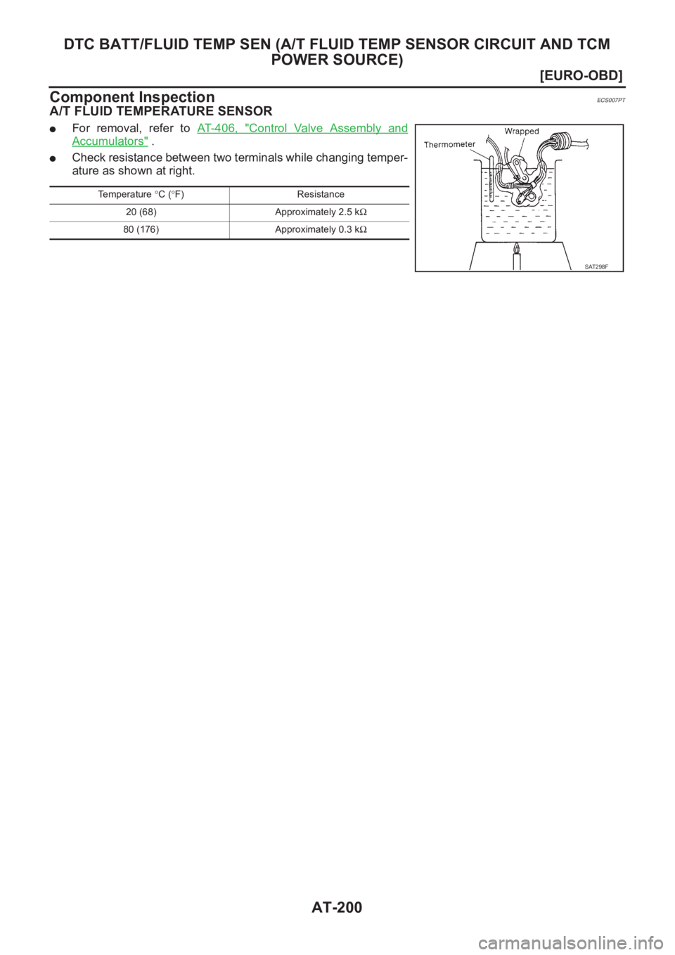
Component Inspection
ECS007PT
A/T FLUID TEMPERATURE SENSOR
●For removal, refer to AT- 4 0 6 , "Control Valve Assembly and
Accumulators" .
●Check resistance between two terminals while changing temper-
ature as shown at right.
Temperature °C (°F) Resistance
20 (68) Approximately 2.5 kΩ
80 (176) Approximately 0.3 kΩ
SAT298F
Page 1670 of 3189
AT-214
[EURO-OBD]
TROUBLE DIAGNOSES FOR SYMPTOMS
4. In “N” Position, Vehicle Moves
ECS007Q5
SYMPTOM:
Vehicle moves forward or backward when selecting “N” position.
1. CHECK PNP SWITCH CIRCUIT
With CONSULT-II
Does “TCM INPUT SIGNALS” in “DATA MONITOR” show damage to PNP switch circuit?
Without CONSULT-II
Does self-diagnosis show damage to PNP switch circuit?
Ye s o r N o
Yes >> Check PNP switch circuit. Refer to AT- 2 3 7 , "21. TCM
Self-diagnosis Does Not Activate (PNP & Overdrive
Control Switches, and Throttle Position Sensor Circuit
Checks)" .
No >> GO TO 2
2. CHECK CONTROL CABLE
Check control cable. Refer to AT- 4 0 8 , "
Control Cable Adjustment" .
OK or NG
OK >> GO TO 3
NG >> Adjust control cable. Refer to AT- 4 0 8 , "
Control Cable
Adjustment" .
3. CHECK A/T FLUID LEVEL
Check A/T fluid level again.
OK or NG
OK >> GO TO 4
NG >> Refill ATF.
SCIA0706E
SAT023JB
SAT638A
Page 1671 of 3189
![NISSAN ALMERA N16 2003 Electronic Repair Manual TROUBLE DIAGNOSES FOR SYMPTOMS
AT-215
[EURO-OBD]
D
E
F
G
H
I
J
K
L
MA
B
AT
4.CHECK A/T FLUID CONDITION
1. Remove oil pan refer to AT-406, "
REMOVAL" .
2. Check A/T fluid condition.
OK or NG
OK](/manual-img/5/57350/w960_57350-1670.png "NISSAN ALMERA N16 2003 Electronic Repair Manual TROUBLE DIAGNOSES FOR SYMPTOMS
AT-215
[EURO-OBD]
D
E
F
G
H
I
J
K
L
MA
B
AT
4.CHECK A/T FLUID CONDITION
1. Remove oil pan refer to AT-406, \"
REMOVAL\" .
2. Check A/T fluid condition.
OK or NG
OK")
TROUBLE DIAGNOSES FOR SYMPTOMS
AT-215
[EURO-OBD]
D
E
F
G
H
I
J
K
L
MA
B
AT
4.CHECK A/T FLUID CONDITION
1. Remove oil pan refer to AT-406, "
REMOVAL" .
2. Check A/T fluid condition.
OK or NG
OK >> GO TO 5
NG >> 1. Disassemble A/T.
2. Check the following items:
–Forward clutch assembly
–Overrun clutch assembly
–Reverse clutch assembly
5.CHECK SYMPTOM
Check again.
OK or NG
OK >>INSPECTION END
NG >> 1. Perform TCM input/output signal inspection.
2. If NG, recheck TCM pin terminals for damage or loose connection with harness connector.
5. Large Shock. “N” → “R” PositionECS007Q6
SYMPTOM:
There is large shock when changing from “N” to “R” position.
1.CHECK SELF-DIAGNOSTIC RESULTS
Does self-diagnosis show damage to A/T fluid temperature sensor,
line pressure solenoid valve or throttle position sensor circuit?
Ye s o r N o
Ye s > >●Check damaged circuit. Refer to the following items.
EURO-OBD
–AT- 1 6 4 , "DTC P0745 LINE PRESSURE SOLENOID
VA LV E"
–AT- 1 8 1 , "DTC P1705 ACCELERATOR PEDAL POSI-
TION (APP) SENSOR"
–AT- 1 9 5 , "DTC BATT/FLUID TEMP SEN (A/T FLUID
TEMP SENSOR CIRCUIT AND TCM POWER
SOURCE)"
No >> GO TO 2
2.CHECK THROTTLE POSITION SENSOR*
*: This sensor means accelerator pedal position (APP) sensor.
Refer to AT- 1 8 1 , "
DTC P1705 ACCELERATOR PEDAL POSITION
(APP) SENSOR" .
OK or NG
OK >> GO TO 3
NG >> Repair or replace Accelerator pedal position (APP) sen-
sor.
SAT171B
SCIA0769E
MCIB9006E
Page 1672 of 3189
AT-216
[EURO-OBD]
TROUBLE DIAGNOSES FOR SYMPTOMS
3. CHECK LINE PRESSURE
Check line pressure at idle with selector lever in “D” position. Refer
to AT-67, "
Line Pressure Test" .
OK or NG
OK >> GO TO 4
NG >> 1. Remove control valve assembly. Refer to AT- 4 0 6 ,
"Control Valve Assembly and Accumulators" .
2. Check the following items:
–Valves to control line pressure (Pressure regulator
valve, pressure modifier valve, pilot valve and pilot fil-
ter)
–Line pressure solenoid valve
4. CHECK SYMPTOM
Check again.
OK or NG
OK >>INSPECTION END
NG >> 1. Perform TCM input/output signal inspection.
2. If NG, recheck TCM pin terminals for damage or loose connection with harness connector.
6. Vehicle Does Not Creep Backward In “R” PositionECS007Q7
SYMPTOM:
Vehicle does not creep backward when selecting “R” position.
1. CHECK A/T FLUID LEVEL
Check A/T fluid level again.
OK or NG
OK >> GO TO 2
NG >> Refill ATF.
SAT494G
SAT638A
![NISSAN ALMERA N16 2003 Electronic Repair Manual DTC BATT/FLUID TEMP SEN (A/T FLUID TEMP SENSOR CIRCUIT AND TCM
POWER SOURCE)
AT-197
[EURO-OBD]
D
E
F
G
H
I
J
K
L
MA
B
AT
Wiring Diagram — AT — BA/FTSECS007PR
YAT 3 6 2](/manual-img/5/57350/w960_57350-1652.png "NISSAN ALMERA N16 2003 Electronic Repair Manual DTC BATT/FLUID TEMP SEN (A/T FLUID TEMP SENSOR CIRCUIT AND TCM
POWER SOURCE)
AT-197
[EURO-OBD]
D
E
F
G
H
I
J
K
L
MA
B
AT
Wiring Diagram — AT — BA/FTSECS007PR
YAT 3 6 2")
![NISSAN ALMERA N16 2003 Electronic Repair Manual AT-214
[EURO-OBD]
TROUBLE DIAGNOSES FOR SYMPTOMS
4. In “N” Position, Vehicle Moves
ECS007Q5
SYMPTOM:
Vehicle moves forward or backward when selecting “N” position.
1. CHECK PNP SWITCH CIRCUIT](/manual-img/5/57350/w960_57350-1669.png "NISSAN ALMERA N16 2003 Electronic Repair Manual AT-214
[EURO-OBD]
TROUBLE DIAGNOSES FOR SYMPTOMS
4. In “N” Position, Vehicle Moves
ECS007Q5
SYMPTOM:
Vehicle moves forward or backward when selecting “N” position.
1. CHECK PNP SWITCH CIRCUIT")
![NISSAN ALMERA N16 2003 Electronic Repair Manual AT-216
[EURO-OBD]
TROUBLE DIAGNOSES FOR SYMPTOMS
3. CHECK LINE PRESSURE
Check line pressure at idle with selector lever in “D” position. Refer
to AT-67, "
Line Pressure Test" .](/manual-img/5/57350/w960_57350-1671.png "NISSAN ALMERA N16 2003 Electronic Repair Manual AT-216
[EURO-OBD]
TROUBLE DIAGNOSES FOR SYMPTOMS
3. CHECK LINE PRESSURE
Check line pressure at idle with selector lever in “D” position. Refer
to AT-67, \"
Line Pressure Test\" .")