2003 NISSAN ALMERA N16 mass air flow sensor
[x] Cancel search: mass air flow sensorPage 1072 of 3189
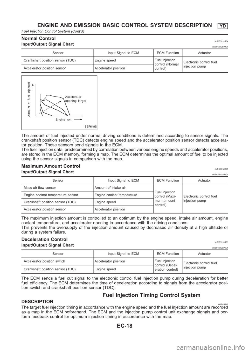
Normal ControlNJEC0612S04Input/Output Signal ChartNJEC0612S0401
Sensor Input Signal to ECM ECM Function Actuator
Crankshaft position sensor (TDC) Engine speedFuel injection
control (Normal
control)Electronic control fuel
injection pump
Accelerator position sensor Accelerator position
SEF649S
The amount of fuel injected under normal driving conditions is determinedaccording to sensor signals. The
crankshaft position sensor (TDC) detects engine speed and the accelerator position sensor detects accelera-
tor position. These sensors send signals to the ECM.
The fuel injection data, predetermined by correlation between various engine speeds and accelerator positions,
are stored in the ECM memory, forming a map. The ECM determines the optimal amount of fuel to be injected
using the sensor signals in comparison with the map.
Maximum Amount ControlNJEC0612S05Input/Output Signal ChartNJEC0612S0501
Sensor Input Signal to ECM ECM Function Actuator
Mass air flow sensor Amount of intake air
Fuel injection
control (Maxi-
mum amount
control)Electronic control fuel
injection pump Engine coolnat temperature sensor Engine coolant temperature
Crankshaft position sensor (TDC) Engine speed
Accelerator position sensor Accelerator position
The maximum injection amount is controlled to an optimum by the engine speed, intake air amount, engine
coolant temperature, and accelerator opening in accordance with the driving conditions.
This prevents the oversupply of the injection amount caused by decreased air density at a high altitude or
during a system failure.
Deceleration ControlNJEC0612S06Input/Output Signal ChartNJEC0612S0601
Sensor Input Signal to ECM ECM Function Actuator
Accelerator position switch Accelerator positionFuel injection
control (Decel-
eration control)Electronic control fuel
injection pump
Crankshaft position sensor (TDC) Engine speed
The ECM sends a fuel cut signal to the electronic control fuel injection pump during deceleration for better
fuel efficiency. The ECM determines the time of deceleration according tosignals from the accelerator posi-
tion switch and crankshaft position sensor (TDC).
Fuel Injection Timing Control System
DESCRIPTIONNJEC0613The target fuel injection timing in accordance with the engine speed and the fuel injection amount are recorded
as a map in the ECM beforehand. The ECM and the injection pump control unit exchange signals and per-
form feedback control for optimum injection timing in accordance with themap.
ENGINE AND EMISSION BASIC CONTROL SYSTEM DESCRIPTIONYD
Fuel Injection Control System (Cont’d)
EC-18
Page 1094 of 3189
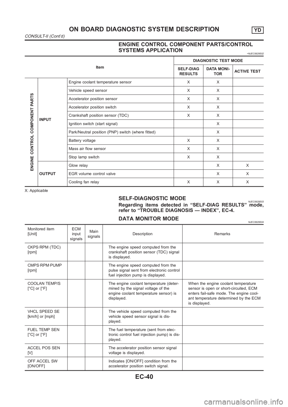
ENGINE CONTROL COMPONENT PARTS/CONTROL
SYSTEMS APPLICATION
=NJEC0629S02
ItemDIAGNOSTIC TEST MODE
SELF-DIAG
RESULTSDATA MONI-
TORACTIVE TEST
ENGINE CONTROL COMPONENT PARTS
INPUTEngine coolant temperature sensor X X
Vehicle speed sensor X X
Accelerator position sensor X X
Accelerator position switch X X
Crankshaft position sensor (TDC) X X
Ignition switch (start signal) X
Park/Neutral position (PNP) switch (where fitted) X
Battery voltage X X
Mass air flow sensor X X
Stop lamp switch X X
OUTPUTGlow relayXX
EGR volume control valve X X
Cooling fan relay X X X
X: Applicable
SELF-DIAGNOSTIC MODENJEC0629S03Regarding items detected in “SELF-DIAG RESULTS” mode,
refer to “TROUBLE DIAGNOSIS — INDEX”, EC-4.
DATA MONITOR MODENJEC0629S04
Monitored item
[Unit]ECM
input
signalsMain
signalsDescription Remarks
CKPS·RPM (TDC)
[rpm]The engine speed computed from the
crankshaft position sensor (TDC) signal
is displayed.
CMPS·RPM·PUMP
[rpm]The engine speed computed from the
pulse signal sent from electronic control
fuel injection pump is displayed.
COOLAN TEMP/S
[°C] or [°F]The engine coolant temperature (deter-
mined by the signal voltage of the
engine coolant temperature sensor) is
displayed.When the engine coolant temperature
sensor is open or short-circuited, ECM
enters fail-safe mode. The engine cool-
ant temperature determined by the ECM
is displayed.
VHCL SPEED SE
[km/h] or [mph]The vehicle speed computed from the
vehicle speed sensor signal is dis-
played.
FUEL TEMP SEN
[°C] or [°F]The fuel temperature (sent from elec-
tronic control fuel injection pump) is dis-
played.
ACCEL POS SEN
[V]The accelerator position sensor signal
voltage is displayed.
OFF ACCEL SW
[ON/OFF]Indicates [ON/OFF] condition from the
accelerator position switch signal.
ON BOARD DIAGNOSTIC SYSTEM DESCRIPTIONYD
CONSULT-II (Cont’d)
EC-40
Page 1095 of 3189
![NISSAN ALMERA N16 2003 Electronic Repair Manual Monitored item
[Unit]ECM
input
signalsMain
signalsDescription Remarks
SPILL/V [°CA] The control position of spill valve (sent
from electronic control fuel injection
pump) is displayed.
BATTERY VOLT [ NISSAN ALMERA N16 2003 Electronic Repair Manual Monitored item
[Unit]ECM
input
signalsMain
signalsDescription Remarks
SPILL/V [°CA] The control position of spill valve (sent
from electronic control fuel injection
pump) is displayed.
BATTERY VOLT [](/manual-img/5/57350/w960_57350-1094.png)
Monitored item
[Unit]ECM
input
signalsMain
signalsDescription Remarks
SPILL/V [°CA] The control position of spill valve (sent
from electronic control fuel injection
pump) is displayed.
BATTERY VOLT [V] The power supply voltage of ECM is
displayed.
P/N POSI SW*1
[ON/OFF] (where
fitted)Indicates [ON/OFF] condition from the
park/neutral position switch signal.
START SIGNAL
[ON/OFF]Indicates [ON/OFF] condition from the
starter signal.After starting the engine, [OFF] is dis-
played regardless of the starter signal.
BRAKE SW
[ON/OFF]Indicates [ON/OFF] condition from the
stop lamp switch signal.
BRAKE SW2
[ON/OFF]Indicates [ON/OFF] condition from the
brake pedal position switch signal.
IGN SW
[ON/OFF]Indicates [ON/OFF] condition from igni-
tion switch signal.
MAS AIR/FL SE [V] The signal voltage of the mass air flow
sensor is displayed.When the engine is stopped, a certain
value is indicated.
INT/A VOLUME [mg/] The intake air volume computed from
the mass air flow sensor signal is dis-
played.
F/CUT SIGNAL
[ON/OFF]The [ON/OFF] condition from decelera-
tion fuel cut signal (sent from electronic
control fuel injection pump) is displayed.
O F F ···F u e l i s c u t o ff .
O N ···F u e l i s n o t c u t o ff .
GLOW RLY
[ON/OFF]The glow relay control condition (deter-
mined by ECM according to the input
signal) is displayed.
COOLING FAN
[LOW/HI/OFF]Indicates the control condition of the
cooling fans (determined by ECM
according to the input signal).
LOW ... Operates at low speed.
HI ... Operates at high speed.
OFF ... Stopped.
BARO SEN [kPa] The barometric pressure (determined by
the signal voltage from the barometric
pressure sensor built into the ECM) is
displayed.
EGR VOL CON/V
[step]Indicates the EGR volume control value
computed by the ECM according to the
input signals.
The opening becomes larger as the
value increases.
*1: On models not equipped with park/neutral position (PNP) switch, “OFF”is always displayed regardless of gear shift position.
NOTE:
Any monitored item that does not match the vehicle being diagnosed is deleted from the display automatically.
GI
MA
EM
LC
FE
CL
MT
AT
AX
SU
BR
ST
RS
BT
HA
SC
EL
IDX
ON BOARD DIAGNOSTIC SYSTEM DESCRIPTIONYD
CONSULT-II (Cont’d)
EC-41
Page 1103 of 3189
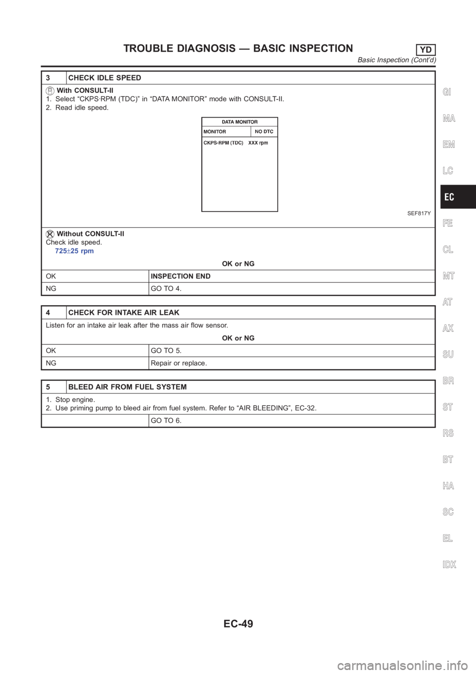
3 CHECK IDLE SPEED
With CONSULT-II
1. Select “CKPS·RPM (TDC)” in “DATA MONITOR” mode with CONSULT-II.
2. Read idle speed.
SEF817Y
Without CONSULT-II
Check idle speed.
725±25 rpm
OK or NG
OKINSPECTION END
NG GO TO 4.
4 CHECK FOR INTAKE AIR LEAK
Listen for an intake air leak after the mass air flow sensor.
OK or NG
OK GO TO 5.
NG Repair or replace.
5 BLEED AIR FROM FUEL SYSTEM
1. Stop engine.
2. Use priming pump to bleed air from fuel system. Refer to “AIR BLEEDING”, EC-32.
GO TO 6.
GI
MA
EM
LC
FE
CL
MT
AT
AX
SU
BR
ST
RS
BT
HA
SC
EL
IDX
TROUBLE DIAGNOSIS — BASIC INSPECTIONYD
Basic Inspection (Cont’d)
EC-49
Page 1109 of 3189
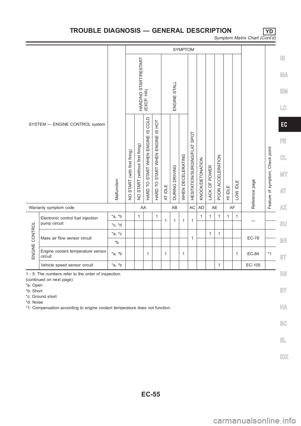
SYSTEM — ENGINE CONTROL system
Malfunction
SYMPTOM
Reference page
Feature of symptom, Check pointHARD/NO START/RESTART
(EXCP. HA)
ENGINE STALL
HESITATION/SURGING/FLAT SPOT
KNOCK/DETONATION
LACK OF POWER
POOR ACCELERATION
HI IDLE
LOW IDLE NO START (with first firing)
NO START (without first firing)
HARD TO START WHEN ENGINE IS COLD
HARD TO START WHEN ENGINE IS HOT
AT IDLE
DURING DRIVING
WHEN DECELERATINGWarranty symptom code AA AB AC AD AE AF
ENGINE CONTROL
Electronic control fuel injection
pump circuit*a, *b 1 1
111111111
—
*c, *d
Mass air flow sensor circuit*a, *c
111
EC-78
*b
Engine coolant temperature sensor
circuit*a, *b 1 1 1 1 EC-84 *1
Vehicle speed sensor circuit *a, *b 1 EC-105
1 - 5: The numbers refer to the order of inspection.
(continued on next page)
*a: Open
*b: Short
*c: Ground short
*d: Noise
*1: Compensation according to engine coolant temperature does not function.
GI
MA
EM
LC
FE
CL
MT
AT
AX
SU
BR
ST
RS
BT
HA
SC
EL
IDX
TROUBLE DIAGNOSIS — GENERAL DESCRIPTIONYD
Symptom Matrix Chart (Cont’d)
EC-55
Page 1110 of 3189
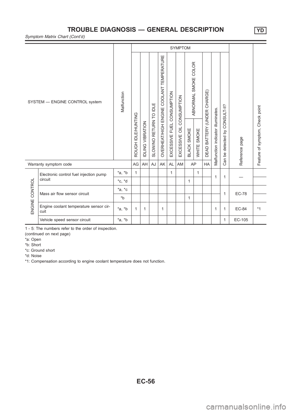
SYSTEM — ENGINE CONTROL system
Malfunction
SYMPTOM
Reference page
Feature of symptom, Check pointROUGH IDLE/HUNTING
IDLING VIBRATION
SLOW/NO RETURN TO IDLE
OVERHEAT/HIGH ENGINE COOLANT TEMPERATURE
EXCESSIVE FUEL CONSUMPTION
EXCESSIVE OIL CONSUMPTION
ABNORMAL SMOKE COLOR
DEAD BATTERY (UNDER CHARGE)
Malfunction indicator illuminates.
Can be detected by CONSULT-II?BLACK SMOKE
WHITE SMOKEWarranty symptom code AG AH AJ AK AL AM AP HA
ENGINE CONTROL
Electronic control fuel injection pump
circuit*a, *b 1 1 1
11 —
*c, *d 1
Mass air flow sensor circuit*a, *c
1 EC-78
*b 1
Engine coolant temperature sensor cir-
cuit*a, *b 1 1 1 1 1 EC-84 *1
Vehicle speed sensor circuit *a, *b 1 EC-105
1 - 5: The numbers refer to the order of inspection.
(continued on next page)
*a: Open
*b: Short
*c: Ground short
*d: Noise
*1: Compensation according to engine coolant temperature does not function.
TROUBLE DIAGNOSIS — GENERAL DESCRIPTIONYD
Symptom Matrix Chart (Cont’d)
EC-56
Page 1121 of 3189
![NISSAN ALMERA N16 2003 Electronic Repair Manual TERMI-
NAL
NO.WIRE
COLORITEM CONDITIONDATA (DC Voltage and Pulse
Signal)
204 L Air conditioner relay[Engine is running]
Air conditioner switch is “OFF”BATTERY VOLTAGE
(11 - 14V)
[Engine is running NISSAN ALMERA N16 2003 Electronic Repair Manual TERMI-
NAL
NO.WIRE
COLORITEM CONDITIONDATA (DC Voltage and Pulse
Signal)
204 L Air conditioner relay[Engine is running]
Air conditioner switch is “OFF”BATTERY VOLTAGE
(11 - 14V)
[Engine is running](/manual-img/5/57350/w960_57350-1120.png)
TERMI-
NAL
NO.WIRE
COLORITEM CONDITIONDATA (DC Voltage and Pulse
Signal)
204 L Air conditioner relay[Engine is running]
Air conditioner switch is “OFF”BATTERY VOLTAGE
(11 - 14V)
[Engine is running]
Both air conditioner switch and blower fan
switch are “ON”
(Compressor is operating)Approximately 0.1V
214 W/B Glow relay Refer to “Glow Control System”, EC-188.
218 B Sensors’ ground[Engine is running]
Warm-up condition
Idle speedApproximately 0V
219 LG/R Cooling fan relay (Low)[Engine is running]
Cooling fan is not operatingBATTERY VOLTAGE
(11 - 14V)
[Engine is running]
Cooling fan is operatingApproximately 0.1V
221 LG/B Cooling fan relay (High)[Engine is running]
Cooling fan is not operating
Cooling fan is operating at low speedBATTERY VOLTAGE
(11 - 14V)
[Engine is running]
Cooling fan is operating at high speedApproximately 0.1V
223 WMass air flow sensor
power supply[Ignition switch “ON”]Approximately 5V
224 R Mass air flow sensor[Engine is running]
Warm-up condition
Idle speed1.5 - 2.0V
313 L/WElectronic control fuel
injection pump[Engine is running]
Warm-up condition
Idle speedApproximately 0.1V
314 L/RElectronic control fuel
injection pump[Engine is running]
Warm-up condition
Idle speedApproximately 0.4V
316 PUElectronic control fuel
injection pump[Engine is running]
Warm-up condition
Idle speedApproximately 2.5V
317 PElectronic control fuel
injection pump[Engine is running]
Warm-up condition
Idle speedApproximately 2.5V
325 G ECM relay (Self-shutoff)[Ignition switch “ON”]
[Ignition switch “OFF”]
For a few seconds after turning ignition switch
“OFF”Approximately 0.25V
[Ignition switch “OFF”]
A few seconds passed after turning ignition
switch “OFF”BATTERY VOLTAGE
(11 - 14V)
331 ORCrankshaft position sen-
sor (TDC) ground[Engine is running]
Warm-up condition
Idle speedApproximately 0V
334 B/REngine coolant tempera-
ture sensor ground[Ignition switch “ON”]Approximately 0V
GI
MA
EM
LC
FE
CL
MT
AT
AX
SU
BR
ST
RS
BT
HA
SC
EL
IDX
TROUBLE DIAGNOSIS — GENERAL DESCRIPTIONYD
ECM Terminals and Reference Value (Cont’d)
EC-67
Page 1132 of 3189
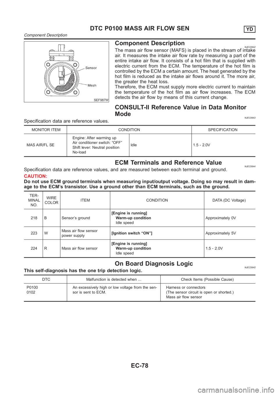
SEF987W
Component DescriptionNJEC0642The mass air flow sensor (MAFS) is placed in the stream of intake
air. It measures the intake air flow rate by measuring a part of the
entire intake air flow. It consists of a hot film that is supplied with
electric current from the ECM. The temperature of the hot film is
controlled by the ECM a certain amount. The heat generated by the
hot film is reduced as the intake air flows around it. The more air,
the greater the heat loss.
Therefore, the ECM must supply more electric current to maintain
the temperature of the hot film as air flow increases. The ECM
detects the air flow by means of this current change.
CONSULT-II Reference Value in Data Monitor
Mode
NJEC0643Specification data are reference values.
MONITOR ITEM CONDITION SPECIFICATION
MAS AIR/FL SEEngine: After warming up
Air conditioner switch: “OFF”
Shift lever: Neutral position
No-loadIdle 1.5 - 2.0V
ECM Terminals and Reference ValueNJEC0644Specification data are reference values, and are measured between each terminal and ground.
CAUTION:
Do not use ECM ground terminals when measuring input/output voltage. Doing so may result in dam-
age to the ECM’s transistor. Use a ground other than ECM terminals, such as the ground.
TER-
MINAL
NO.WIRE
COLORITEM CONDITION DATA (DC Voltage)
218 B Sensor’s ground[Engine is running]
Warm-up condition
Idle speedApproximately 0V
223 WMass air flow sensor
power supply[Ignition switch “ON”]Approximately 5V
224 R Mass air flow sensor[Engine is running]
Warm-up condition
Idle speed1.5 - 2.0V
On Board Diagnosis LogicNJEC0645This self-diagnosis has the one trip detection logic.
DTC Malfunction is detected when ... Check Items (Possible Cause)
P0100
0102An excessively high or low voltage from the sen-
sor is sent to ECM.Harness or connectors
(The sensor circuit is open or shorted.)
Mass air flow sensor
DTC P0100 MASS AIR FLOW SENYD
Component Description
EC-78