2003 NISSAN 350Z wheel
[x] Cancel search: wheelPage 11 of 227
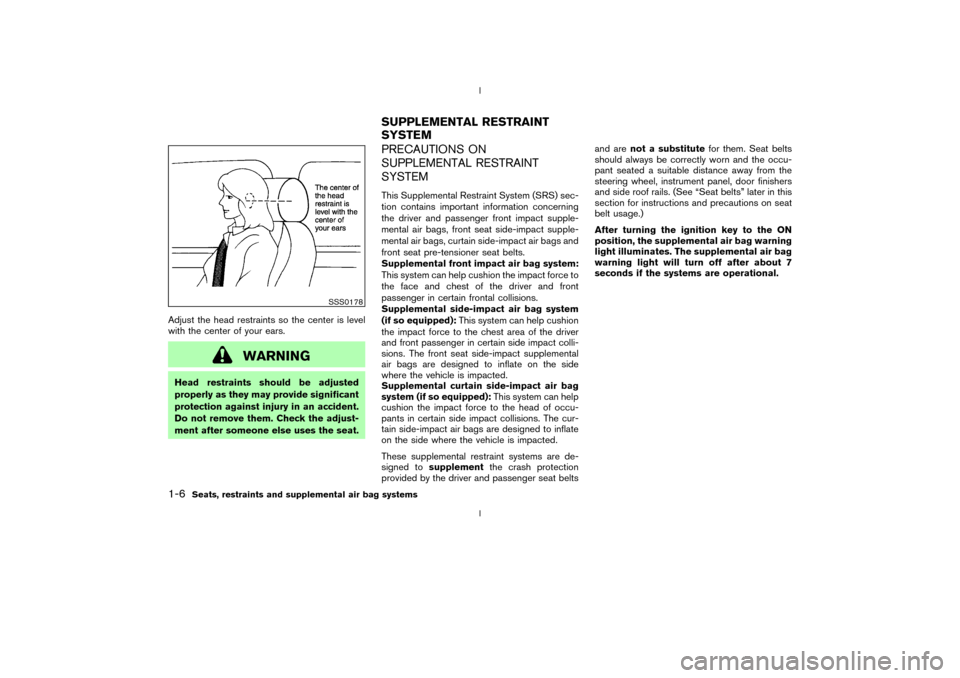
Adjust the head restraints so the center is level
with the center of your ears.
WARNING
Head restraints should be adjusted
properly as they may provide significant
protection against injury in an accident.
Do not remove them. Check the adjust-
ment after someone else uses the seat.
PRECAUTIONS ON
SUPPLEMENTAL RESTRAINT
SYSTEMThis Supplemental Restraint System (SRS) sec-
tion contains important information concerning
the driver and passenger front impact supple-
mental air bags, front seat side-impact supple-
mental air bags, curtain side-impact air bags and
front seat pre-tensioner seat belts.
Supplemental front impact air bag system:
This system can help cushion the impact force to
the face and chest of the driver and front
passenger in certain frontal collisions.
Supplemental side-impact air bag system
(if so equipped):This system can help cushion
the impact force to the chest area of the driver
and front passenger in certain side impact colli-
sions. The front seat side-impact supplemental
air bags are designed to inflate on the side
where the vehicle is impacted.
Supplemental curtain side-impact air bag
system (if so equipped):This system can help
cushion the impact force to the head of occu-
pants in certain side impact collisions. The cur-
tain side-impact air bags are designed to inflate
on the side where the vehicle is impacted.
These supplemental restraint systems are de-
signed tosupplementthe crash protection
provided by the driver and passenger seat beltsand arenot a substitutefor them. Seat belts
should always be correctly worn and the occu-
pant seated a suitable distance away from the
steering wheel, instrument panel, door finishers
and side roof rails. (See ªSeat beltsº later in this
section for instructions and precautions on seat
belt usage.)
After turning the ignition key to the ON
position, the supplemental air bag warning
light illuminates. The supplemental air bag
warning light will turn off after about 7
seconds if the systems are operational.
SSS0178
SUPPLEMENTAL RESTRAINT
SYSTEM
1-6
Seats, restraints and supplemental air bag systems
Z
02.9.13/Z33-D/V5.0
X
Page 12 of 227
WARNING
IThe supplemental front air bags ordi-
narily will not inflate in the event of a
side impact, rear impact, roll over, or
lower severity frontal collision. Al-
ways wear your seat belts to help
reduce the risk or severity of injury in
various kinds of accidents.
IThe seat belts and the supplemental
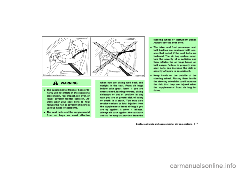
front air bags are most effectivewhen you are sitting well back and
upright in the seat. Front air bags
inflate with great force. If you are
unrestrained, leaning forward, sitting
sideways or out of position in any
way, you are at greater risk of injury
or death in a crash. You may also
receive serious or fatal injuries from
the supplemental front air bag if you
are up against it when it inflates.
Always sit back against the seatback
and as far away as practical from thesteering wheel or instrument panel.
Always use the seat belts.
IThe driver and front passenger seat
belt buckles are equipped with sen-
sors that detect if the seat belts are
fastened. The air bag system moni-
tors the severity of a collision and
then inflates the air bags based on
belt usage. Failure to properly wear
seat belts can increase the risk or
severity of injury in an accident.
IKeep hands on the outside of the
steering wheel. Placing them inside
the steering wheel rim could increase
the risk that they are injured when
the supplemental front air bag in-
flates.
SSS0131Seats, restraints and supplemental air bag systems
1-7
Z
02.9.13/Z33-D/V5.0
X
Page 16 of 227
out of the window or lean against the
door. Some examples of dangerous
riding positions are shown in the pre-
vious illustrations.
IDo not use seat covers on the front
seatbacks. They may interfere with
supplemental side air bag inflation.
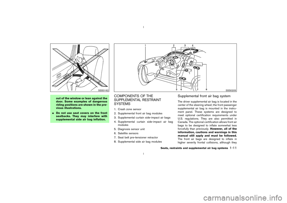
COMPONENTS OF THE
SUPPLEMENTAL RESTRAINT
SYSTEMS1. Crash zone sensor
2. Supplemental front air bag modules
3. Supplemental curtain side-impact air bags
4. Supplemental curtain side-impact air bag
modules
5. Diagnosis sensor unit
6. Satellite sensors
7. Seat belt pre-tensioner retractor
8. Supplemental side air bag modules
Supplemental front air bag systemThe driver supplemental air bag is located in the
center of the steering wheel; the front passenger
supplemental air bag is mounted in the instru-
ment panel. These systems are designed to
meet optional certification requirements under
U.S. regulations. They are also permitted in
Canada. The optional certification allows front air
bags to be designed to inflate somewhat less
forcefully than previously.However, all of the
information, cautions and warnings in this
manual still apply and must be followed.
The front air bags are designed to inflate in
higher severity frontal collisions, although they
SSS0162
SSS0205
Seats, restraints and supplemental air bag systems
1-11
Z
02.9.13/Z33-D/V5.0
X
Page 17 of 227
may inflate if the forces in another type of
collision are similar to those of a higher severity
frontal impact. They may not inflate in certain
frontal collisions. Vehicle damage (or lack of it) is
not always an indication of proper supplemental
air bag operation.
The supplemental air bag system has dual stage
inflators for both the driver and passenger air
bags. The system monitors information from the
crash zone sensor, the diagnosis sensor unit and
seat belt buckle sensors that detect if the seat
belts are fastened, inflator operation is based on
the severity of a collision and whether the seat
belts are being used. Only one front air bag may
inflate in a crash, depending on the crash sever-
ity and whether the front occupants are belted or
unbelted. This does not indicate improper per-
formance of the system. If you have any ques-
tions about the performance of your air bag
system, please contact your NISSAN dealer.
When the supplemental front air bag inflates, a
fairly loud noise may be heard, followed by
release of smoke. This smoke is not harmful and
does not indicate a fire. Care should be taken
not to inhale it, as it may cause irritation and
choking. Those with a history of a breathing
condition should get fresh air promptly.
Supplemental front air bags, along with the use
of seat belts, help to cushion the impact force onthe face and chest of the front occupants. They
can help save lives and reduce serious injuries.
However, an inflating front air bag may cause
facial abrasions or other injuries. Front air bags
do not provide restraint to the lower body.
The seat belts should be correctly worn and the
driver and passenger seated upright as far as
practical away from the steering wheel or instru-
ment panel. The supplemental front air bags
inflates quickly in order to help protect the front
occupants. Because of this, the force of the front
air bag inflating can increase the risk of injury if
the occupant is too close to, or is against, the air
bag module during inflation. The air bag will
deflate quickly after the collision is over.
After turning the ignition key to the ON
position, the supplemental air bag warning
light illuminates. The supplemental air bag
warning light will turn off after about 7
seconds if the system is operational.
WARNING
IDo not place any objects on the
steering wheel pad or on the instru-
ment panel. Also, do not place any
objects between any occupant andthe steering wheel or instrument
panel. Such objects may become
dangerous projectiles and cause in-
jury if the supplemental front air bag
inflates.
IRight after inflation, several air bag
system components will be hot. Do
not touch them; you may severely
burn yourself.
INo unauthorized changes should be
made to any components or wiring of
the supplemental front air bag sys-
tem. This is to prevent accidental in-
flation of the air bag or damage to
the air bag system.
IDo not make unauthorized changes
to your vehicle's electrical system,
suspension system or front end
structure. This could affect proper
operation of the supplemental air
bag system.
ITampering with the supplemental
front air bag system may result in
serious personal injury. Tampering
1-12
Seats, restraints and supplemental air bag systems
Z
02.9.13/Z33-D/V5.0
X
Page 18 of 227
includes changes to the steering
wheel and the instrument panel as-
sembly by placing material over the
steering wheel pad, above the dash-
board, or by installing additional trim
material around the air bag system.
IWork around and on the supplemen-
tal front air bag system should be
done by a NISSAN dealer. Installa-
tion of electrical equipment should
also be done by a NISSAN dealer.
The yellow and orange Supplemental
Restrain System (SRS) wiring and
connectors should not be modified or
disconnected. Unauthorized electri-
cal test equipment and probing de-
vices should not be used on the air
bag system.
IA cracked windshield should be re-
placed immediately by a qualified re-
pair facility. A cracked windshield
could affect inflation of the supple-
mental air bag system.
IThe SRS wiring harness connectors
are yellow and orange for easyidentification.
When selling your vehicle, we request that you
inform the buyer about the supplemental front air
bag system and guide the buyer to the appro-
priate sections in this Owner's Manual.
Supplemental side air bag and curtain
side-impact air bag systems (if so
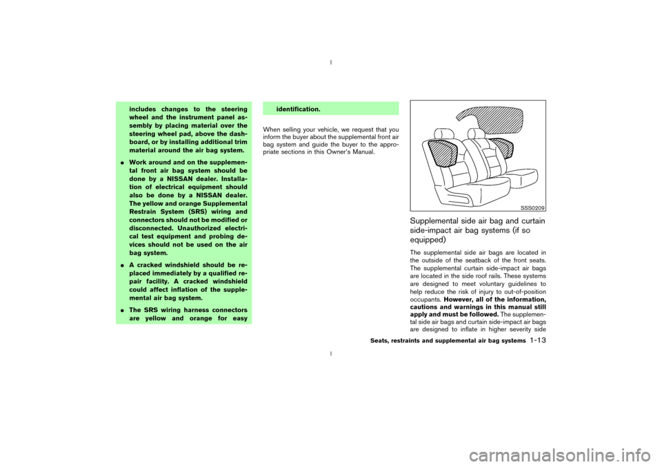
equipped)The supplemental side air bags are located in
the outside of the seatback of the front seats.
The supplemental curtain side-impact air bags
are located in the side roof rails. These systems
are designed to meet voluntary guidelines to
help reduce the risk of injury to out-of-position
occupants.However, all of the information,
cautions and warnings in this manual still
apply and must be followed.The supplemen-
tal side air bags and curtain side-impact air bags
are designed to inflate in higher severity side
SSS0209
Seats, restraints and supplemental air bag systems
1-13
Z
02.9.13/Z33-D/V5.0
X
Page 41 of 227

1. Headlight and turn signal switch (P.2-21)
2. Instrument brightness control switch
(P.2-23)
3. Driver supplemental air bag (P.1-6)/Horn
(P.2-24)
4. Meters/gauges (P.2-3)5. Cruise control main/set switch (P.5-15)
6. Trip computer mode/setting switch (P.2-8)
7. Windshield wiper/washer switch (P.2-19)
8. Center ventilator (P.4-2)
9. Cup holder (P.2-30)
10. Passenger supplemental air bag (P.1-6)11. Side ventilator (P.4-2)
12. VDC (Vehicle dynamic control) OFF switch
(P.2-26) or TCS (Traction control system)
OFF switch (P.2-26)
13. Fuel filler lid opener switch (P.3-10)
14. Hood lock release handle (P.3-8)
15. Fuse box (P.8-23)
16. Tilting steering wheel lock lever (P.3-12)
17. Ignition switch/steering lock (P.5-5)
18. Navigation system* or Instrument pocket
(P.2-29)
19. Rear window and outside mirror (if so
equipped) defroster switch (P.2-21)
20. Heater/air conditioner control (P.4-3)
21. Audio system (P.4-6)/Clock (P.2-27)
22. Heated seat switch (P.2-25)
23. Hazard warning flasher switch (P.2-24)
24. Ashtray (P.2-28) or Tray (P.2-30)
See the page indicated in parentheses for
operating details.
*: Refer to the separate Navigation System
Owner's Manual.
SIC1943
INSTRUMENT PANEL2-2
Instruments and controls
Z
02.9.13/Z33-D/V5.0
X
Page 48 of 227

temperature displayed on various signs or bill-
boards.Distance to empty (dte Ð mile or km)The distance to empty (dte) mode provides you
with an estimation of the distance that can be
driven before refueling. The dte is constantly
being calculated, based on the amount of fuel in
the fuel tank and the actual fuel consumption.
The display is updated every 30 seconds.
The dte mode includes a low range warning
feature: when the fuel level is low, the dte mode
is automatically selected and the digits blink in
order to draw the driver's attention. Press the
mode switch
qAif you wish to return to the mode
that was selected before the warning occurred.
The dte indicator will remain blinking until the
vehicle is refuelled.
When the fuel level drops even lower, the dte
display will change to (----).
NOTE:
IIf the amount of fuel added while the
ignition switch is OFF is small, the dis-
play just before the ignition switch is
turned OFF may continue to be dis-
played.
IWhen driving uphill or rounding curves,
the fuel in the tank shifts, which maymomentarily change the display.
Average fuel consumption
(Mpg or l/100 km)The average fuel consumption mode shows the
average fuel consumption since the last reset.
Resetting is done by pressing the trip computer
setting switch
qB
for more than approximately 1
second. (The average speed is also reset at the
same time.)
The display is updated every 30 seconds. At
about the first 1/3 miles (500 m) after a reset,
the display shows (----).
Average speed (MPH or km/h)The average speed mode shows the average
vehicle speed since the last reset. Resetting is
done by pressing the setting switch
qB
for more
than approximately 1 second. (The average fuel
consumption is also reset at the same time.)
The display is updated every 30 seconds. The
first 30 seconds after a reset, the display shows
(----).
Elapsed time (h:m:s)The elapsed time mode shows the time since the
last reset. The displayed time can be reset by
pressing the trip computer setting switch
qB
for
more than approximately 1 second. (The tripodometer is also reset at the same time.)
Trip odometer (MLS or km)The trip odometer mode shows the total dis-
tance the vehicle has been driven since the last
reset. Resetting is done by pressing the setting
switch
qBfor more than approximately 1 second.
(The elapsed time is also reset at the same time.)
Stopwatch (h:m:s)You can use the trip computer as a stopwatch.
Each time the trip computer setting switch
qB
is
pressed, the stopwatch will be operated as
follows:
After 100 hours, the time will start from the reset
display again.
Even if the display is switched to the other mode
while the time is starting, the stopwatch contin-
ues to advance until you stop the time in the
stopwatch mode. When the ignition switch is
turned OFF, the time is reset.Tire pressure indicator (PSI) (if so
equipped)The tire pressure indicator shows tire pressure
(0 - 51 psi) of all wheels (except the spare tire)
Instruments and controls
2-9
Z
02.9.13/Z33-D/V5.0
X
Page 49 of 227
by sending a signal from a sensor that is installed
in each wheel. Press the trip computer setting
switch
qBto change the display to F (front) or R
(rear).
The tire pressure sensor will activate only when
the vehicle is driven at speeds above 20 MPH
(32 km/h). If the tire pressure signal cannot be
received correctly, the display shows (----).
The tire pressure indicator mode includes a low
tire pressure warning feature. If the vehicle is
being driven with very low tire pressure or a flat
tire, the tire pressure indicator mode is automati-
cally selected and the PSI indicator will blink in
order to attract the driver's attention. Press the
trip computer mode switch
qA
if you wish to
return to the mode that was selected before the
warning occurred. The PSI indicator will con-
tinue blinking until the tire pressure of each tire is
properly adjusted.
For additional information, see ªLow tire pres-
sure warning systemº in the ª5. Starting and
drivingº section and ªFlat tireº in the ª6. In case
of emergencyº section.
Tire pressure shown in the display may rise
or fall while driving depending on the driv-
ing conditions (heat, etc.) and/or the out-
side temperature. This does not indicate a
system malfunction.
WARNING
The low tire pressure warning system is
not a substitute for the regular tire pres-
sure check. Be sure to check the tire
pressure regularly and adjust it to the
COLD tire pressure shown in the tire
placard.Up-shift indicator setting (rpm) (for
manual transmission models)The up-shift indicator setting mode is used to
set the desired engine speed (rpm) for the
up-shift indicator (situated in the tachometer) to
illuminate. When the engine speed approaches
or reaches the set figure, the up-shift indicator
will flash or illuminate to show the driver the
timing for shifting into a higher gear. See ªDriving
the vehicleº in the ª5. Starting and drivingº
section for the use of the up-shift indicator.
When the up-shift indicator setting mode is
selected, the rpm indicator blinks and the engine
speed currently set is displayed. (The initial
factory setting is 6,600 rpm.) The figure can be
changed between 2,000 and 8,000 rpm by
pressing trip computer setting switch
qB. Press-
ing the switch for less than approximately 1second will add the figure by 100 rpm. If press-
ing for more than approximately 1 second, the
figure will increase by 500 rpm.
If the battery cable is disconnected, the set
engine speed will be returned to the initial figure
(6,600 rpm).
Display priorityIf a low outside air temperature warning,
low dte (distance to empty) range warning
and low tire pressure warning occur simul-
taneously, other display modes switch au-
tomatically to the outside air temperature
display.
When trip computer mode switch
qA
is
pressed, the display switches to the mode
chosen before the warning display, but the
ICY indicator will continue blinking.
2-10
Instruments and controls
Z
02.9.13/Z33-D/V5.0
X