Page 1086 of 4500
Replace the RH side by using the same procedures as for the LH side.
The procedures listed below are for the LH side.
1.REMOVE REAR SEAT CUSHION ASSY (SEE OVERHAUL
- FIXED TYPE or OVERHAUL -
POWER ADJUSTER TYPE
)
2.REMOVE REAR SEAT HEAD REST ASSY (SEE OVERHAUL
- FIXED TYPE or OVERHAUL -
POWER ADJUSTER TYPE )
3.REMOVE REAR SEATBACK ASSY (SEE OVERHAUL
- FIXED TYPE or OVERHAUL -
POWER ADJUSTER TYPE
)
4.REMOVE REAR WHEEL
5.REMOVE REAR WHEEL HOUSE LH LINER
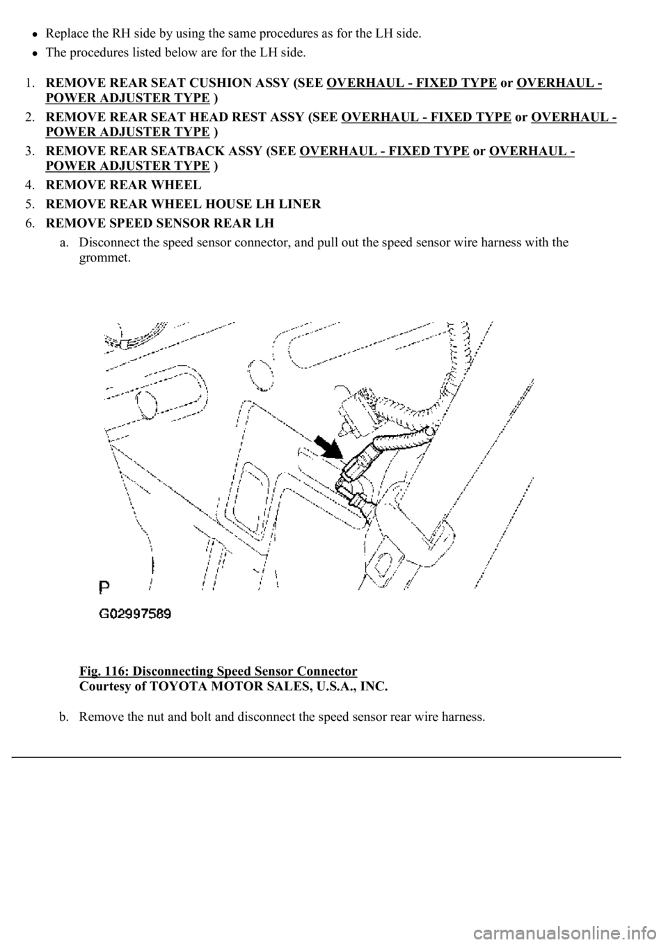
6.REMOVE SPEED SENSOR REAR LH
a. Disconnect the speed sensor connector, and pull out the speed sensor wire harness with the
grommet.
Fig. 116: Disconnecting Speed Sensor Connector
Courtesy of TOYOTA MOTOR SALES, U.S.A., INC.
b. Remove the nut and bolt and disconnect the speed sensor rear wire harness.
Page 1093 of 4500
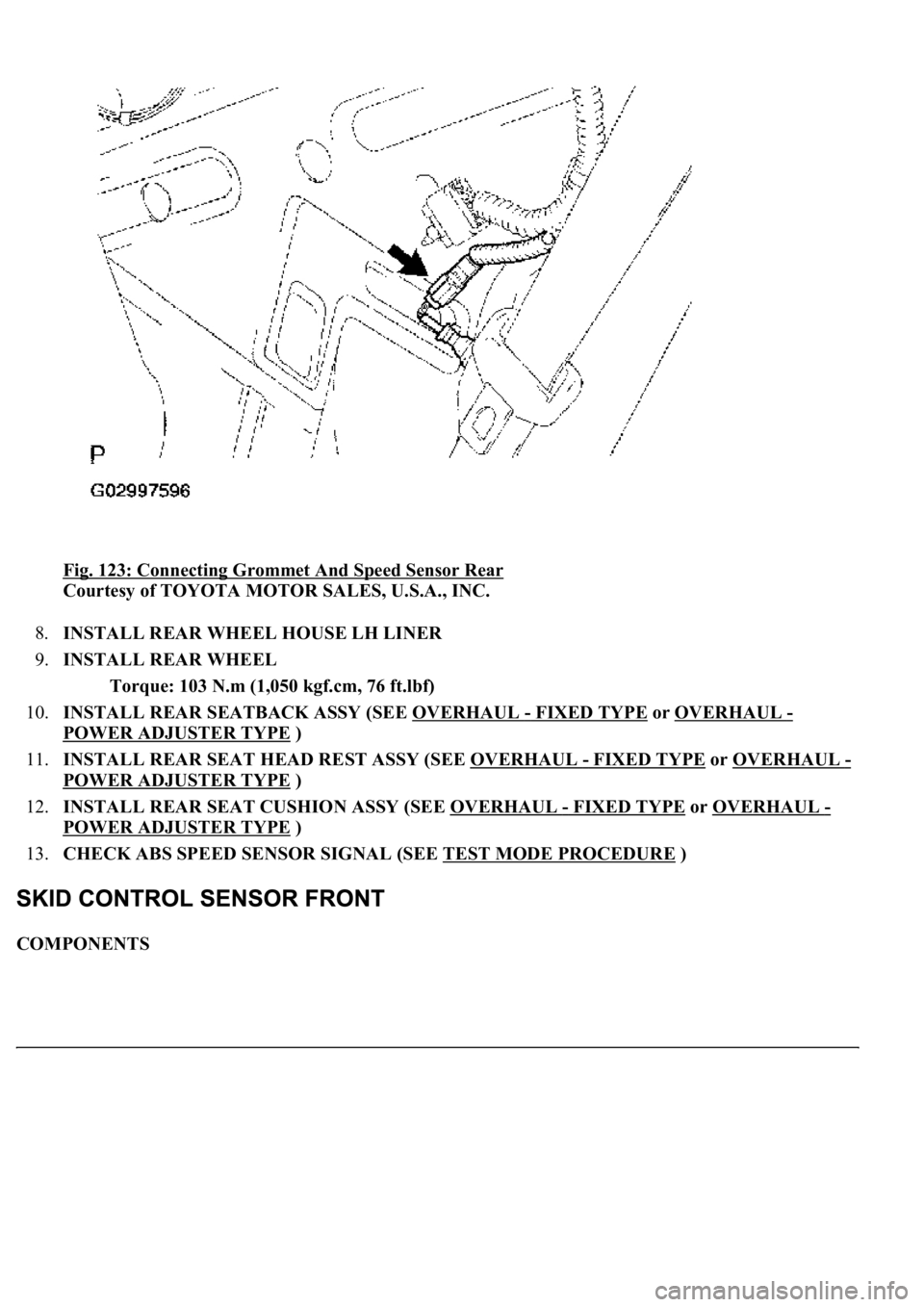
Fig. 123: Connecting Grommet And Speed Sensor Rear
Courtesy of TOYOTA MOTOR SALES, U.S.A., INC.
8.INSTALL REAR WHEEL HOUSE LH LINER
9.INSTALL REAR WHEEL
Torque: 103 N.m (1,050 kgf.cm, 76 ft.lbf)
10.INSTALL REAR SEATBACK ASSY (SEE OVERHAUL
- FIXED TYPE or OVERHAUL -
POWER ADJUSTER TYPE
)
11.INSTALL REAR SEAT HEAD REST ASSY (SEE OVERHAUL
- FIXED TYPE or OVERHAUL -
POWER ADJUSTER TYPE )
12.INSTALL REAR SEAT CUSHION ASSY (SEE OVERHAUL
- FIXED TYPE or OVERHAUL -
POWER ADJUSTER TYPE
)
13.CHECK ABS SPEED SENSOR SIGNAL (SEE TEST MODE PROCEDURE
)
COMPONENTS
Page 1104 of 4500
Fig. 133: Connecting Yawrate Sensor Connector
Courtesy of TOYOTA MOTOR SALES, U.S.A., INC.
6.INSTALL REAR CONSOLE ARMREST ASSY (SEE REPLACEMENT
)
7.INSTALL CONSOLE BOX CARPET
8.INSTALL CONSOLE UPPER REAR PANEL SUB-ASSY (SEE REPLACEMENT
)
9.PERFORM YAWRATE SENSOR ZERO POINT CALIBRATION (SEE CALIBRATION
)
REPLACEMENT
1.(SEE PRECAUTION
)
2.SEPARATE BATTERY NEGATIVE TERMINAL (SEE PRECAUTION
)
3.PLACE FRONT WHEELS FACING STRAIGHT AHEAD
4.REMOVE HORN BUTTON ASSY (SEE OVERHAUL
)
5.REMOVE STEERING WHEEL ASSY (SEE OVERHAUL
)
<00360036003700030013001c001c001800130010001800130013001400160003000b0013001c001c00180014001000130018001300140013000f00030013001c001c00180015001000130018001300140013000f00030013001c001c001800160010001300
18001300150013000f00030013001c001c0018001700100013[5021)
6.REMOVE STEERING COLUMN COVER (SEE OVERHAUL
)
Page 3919 of 4500
Front power seat:
FRONT POWER SEAT - CUSTOMIZE PARAMETERS
1.INITIALIZE FRONT POWER SEAT CONTROL SYSTEM
a. The power seat ECU must be initialized under any of the following conditions.
The battery is disconnected.
The D/C cut fuse is replaced.
The power seat switch (power seat ECU) is replaced.
The power seat assy is removed from the vehicle.
b. Initialize the power seat ECU as follows.
1. Using the seat switches, fully slide the seat forward, fully recline the seatback forward, and
fully raise the seat cushion and headrest.
2. Using the seat switches, fully slide the seat rearward, fully recline the seatback rearward, and
fully lower the seat cushion and headrest.
Display (Item)DefaultContentsSetting
HEADREST CONTROLAVAILFunction that activates
physique compensation
headrest control when driver
seat is moved (sliding).NOT AVL/AVAIL
Page 3969 of 4500
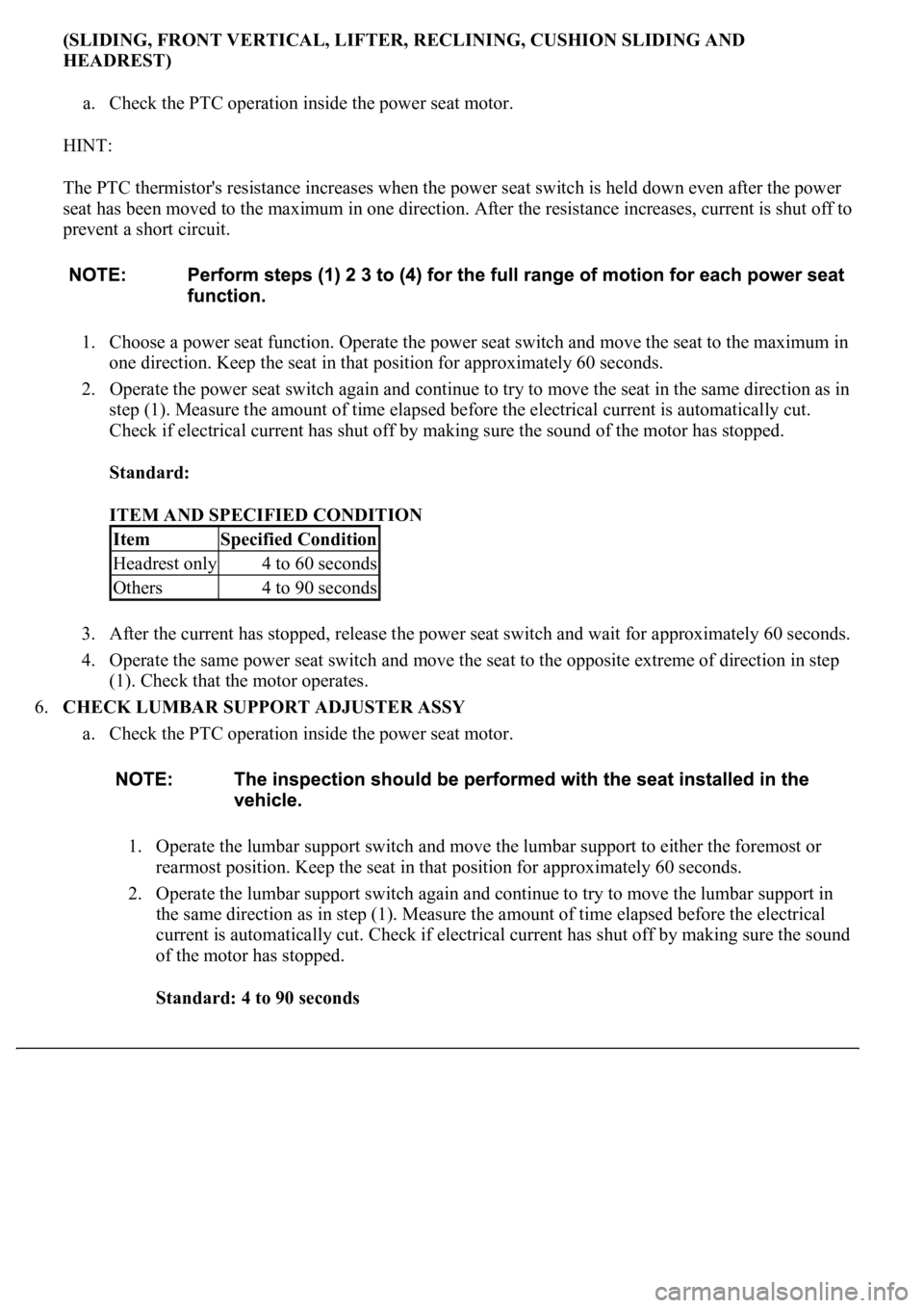
(SLIDING, FRONT VERTICAL, LIFTER, RECLINING, CUSHION SLIDING AND
HEADREST)
a. Check the PTC operation inside the power seat motor.
HINT:
The PTC thermistor's resistance increases when the power seat switch is held down even after the power
seat has been moved to the maximum in one direction. After the resistance increases, current is shut off to
prevent a short circuit.
1. Choose a power seat function. Operate the power seat switch and move the seat to the maximum in
one direction. Keep the seat in that position for approximately 60 seconds.
2. Operate the power seat switch again and continue to try to move the seat in the same direction as in
step (1). Measure the amount of time elapsed before the electrical current is automatically cut.
Check if electrical current has shut off by making sure the sound of the motor has stopped.
Standard:
ITEM AND SPECIFIED CONDITION
3. After the current has stopped, release the power seat switch and wait for approximately 60 seconds.
4. Operate the same power seat switch and move the seat to the opposite extreme of direction in step
(1). Check that the motor operates.
6.CHECK LUMBAR SUPPORT ADJUSTER ASSY
a. Check the PTC operation inside the power seat motor.
1. Operate the lumbar support switch and move the lumbar support to either the foremost or
rearmost position. Keep the seat in that position for approximately 60 seconds.
2. Operate the lumbar support switch again and continue to try to move the lumbar support in
the same direction as in step (1). Measure the amount of time elapsed before the electrical
current is automatically cut. Check if electrical current has shut off by making sure the sound
of the motor has stopped.
Standard: 4 to 90 seconds
ItemSpecified Condition
Headrest only4 to 60 seconds
Others4 to 90 seconds