2003 LEXUS LS430 Ecm
[x] Cancel search: EcmPage 1591 of 4500
COMMUNICATION
1.GENERAL
The climate control seat system creates cold or warm air to increase the comfort of seats that have
become hot or cold.
The air is heated or cooled by the Peltier element on the back of the seat cushion pad and seatback. The
air is then sent to the seat cushion and seatback with the fan installed under the seat. The fan is operated
by pressing the climate control seat switch.
The climate control seat switch has several modes that vary the quantity of air to be sent to the seat. There
are 7 modes in total: 3 cooled air modes, 3 heated air modes and ventilation mode.
HINT:
When the highest level for cooled air operates for 15 minutes, the quantity of air falls 1 level.
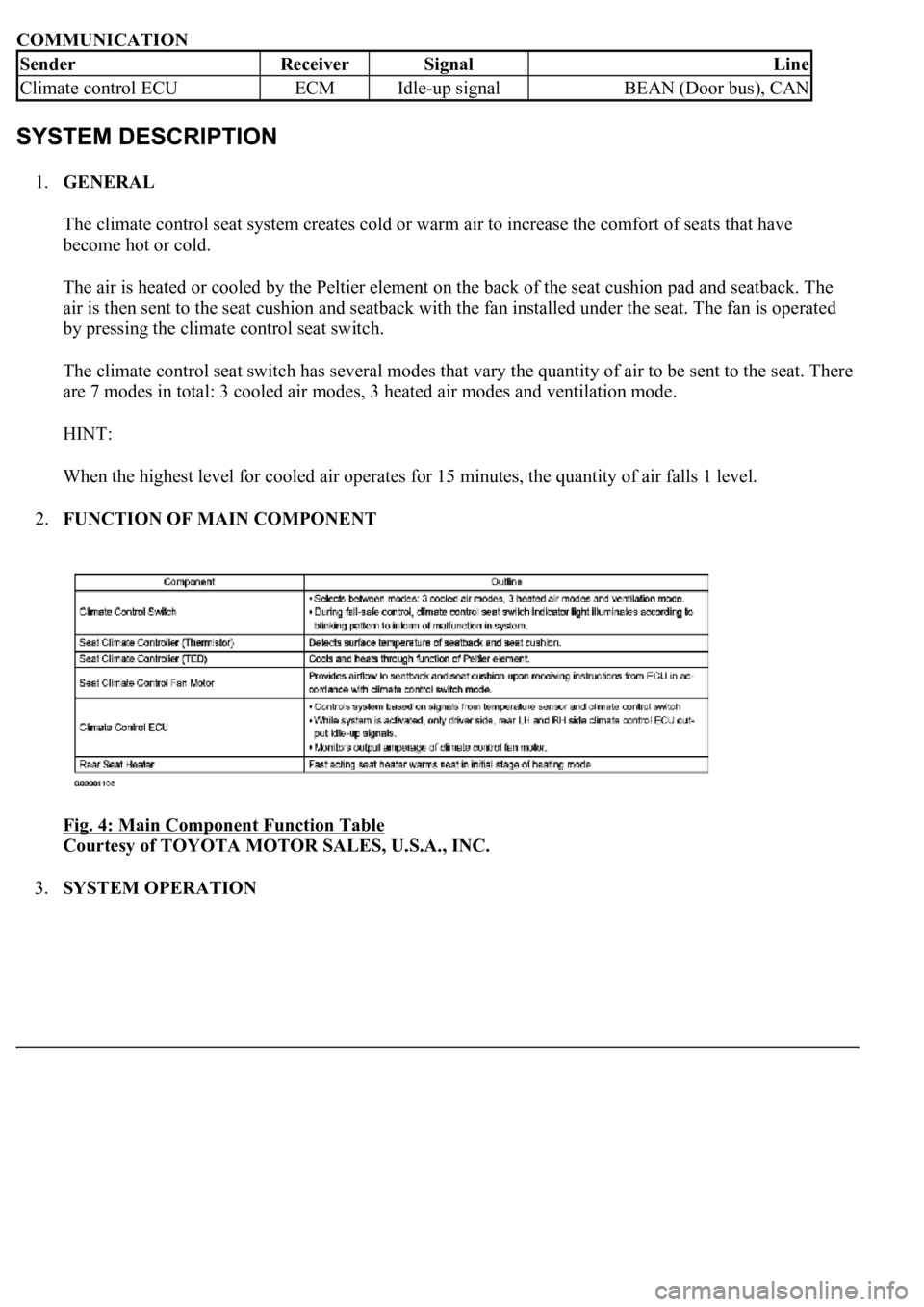
2.FUNCTION OF MAIN COMPONENT
Fig. 4: Main Component Function Table
Courtesy of TOYOTA MOTOR SALES, U.S.A., INC.
3.SYSTEM OPERATION
SenderReceiverSignalLine
Climate control ECUECMIdle-up signalBEAN (Door bus), CAN
Page 1743 of 4500
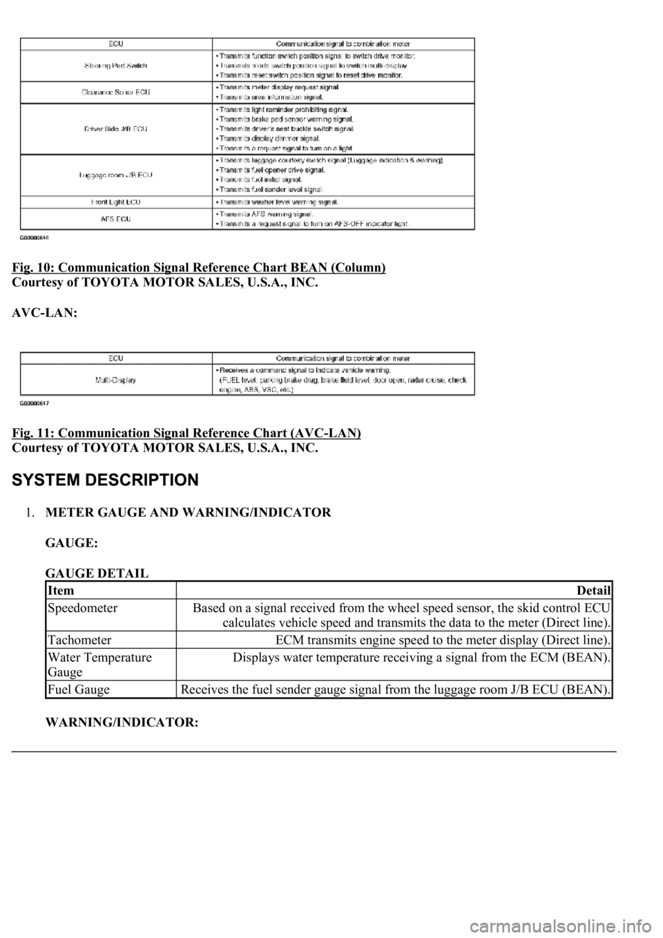
Fig. 10: Communication Signal Reference Chart BEAN (Column)
Courtesy of TOYOTA MOTOR SALES, U.S.A., INC.
AVC-LAN:
Fig. 11: Communication Signal Reference Chart (AVC
-LAN)
Courtesy of TOYOTA MOTOR SALES, U.S.A., INC.
1.METER GAUGE AND WARNING/INDICATOR
GAUGE:
GAUGE DETAIL
WARNING/INDICATOR:
ItemDetail
SpeedometerBased on a signal received from the wheel speed sensor, the skid control ECU
calculates vehicle speed and transmits the data to the meter (Direct line).
TachometerECM transmits engine speed to the meter display (Direct line).
Water Temperature
GaugeDisplays water temperature receiving a signal from the ECM (BEAN).
Fuel GaugeReceives the fuel sender gauge signal from the luggage room J/B ECU (BEAN).
Page 1744 of 4500
WARNING/INDICATOR DETAILS
2.MULTI-INFORMATION DISPLAY
ItemDetail
TURN SIGNALReceives the turn signal from the driver side J/B ECU (Direct line).
BEAMReceives the beam signal from the driver side J/B ECU (BEAN).
CHARGEReceives the malfunction charge signal from the ECM (BEAN).
CHECK E/GReceives the malfunction charge signal from the ECM (Direct line).
DOOROpen door indicator comes on receiving from a signal each door ECU (BEAN).
D BELTReceives the driver seat belt signal (Unfastened) from the driver side J/B ECU
(BEAN).
BELTReceives the passenger seat belt signal (Unfastened) from the airbag sensor ECU
(BEAN).
BRAKEReceives the parking brake switch/brake fluid level warning signal from the skid
control ECU (BEAN).
CRUISEReceives the malfunction signal from the ECM (BEAN).
AIR BAGReceives the malfunction signal from the airbag sensor ECU (BEAN).
A/TPReceives the P signal from the ECM (BEAN).
A/T RReceives the R signal from the ECM (BEAN).
A/T NReceives the N signal from the ECM (BEAN).
A/T DReceives the D signal from the ECM (BEAN).
A/T SReceives the S signal from the ECM (BEAN).
SLIPReceives the malfunction signal from the skid control ECU (BEAN).
VSC OFFReceives the malfunction signal from the skid control ECU (BEAN).
WASHERReceives the washer level warning switch from the front light control ECU (BEAN).
ABSReceives the malfunction skid control ECU (BEAN).
TEMS SPORTReceives the sports mode signal from the air suspension ECU (Direct line).
ECT POWERReceives the power mode signal from the ECM (BEAN).
ECT SNOWReceives the snow mode signal from the ECM (BEAN).
AFS OFFReceives the AFS OFF signal from the AFS ECU (BEAN).
TAIL or HEADReceives the malfunction tail or head signal from driver side J/B ECU (BEAN).
Page 1795 of 4500
Fig. 52: Identifying Signal Waveform
Courtesy of TOYOTA MOTOR SALES, U.S.A., INC.
NG: Go to step 5
OK: REPLACE COMBINATION METER ASSY (SEE OVERHAUL
)
5.CHECK HARNESS AND CONNECTOR (ECM - COMBINATION METER ASSY) (SEE HOW
TO PROCEED WITH TROUBLESHOOTING )
a. Disconnect the C12 and E2 connectors.
b. Measure the resistance according to the value (s) in the table below.
Standard
C12 AND E2 CONNECTORS RESISTANCE SPECIFICATIONS
Tester ConnectionConditionSpecified Condition
C12-4 - E2-16AlwaysBelow 1 ohms
C12-4 - Body groundAlways10 kohms or higher
Page 1810 of 4500
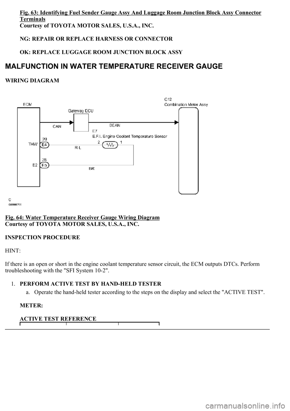
Fig. 63: Identifying Fuel Sender Gauge Assy And Luggage Room Junction Block Assy Connector
Terminals
Courtesy of TOYOTA MOTOR SALES, U.S.A., INC.
NG: REPAIR OR REPLACE HARNESS OR CONNECTOR
OK: REPLACE LUGGAGE ROOM JUNCTION BLOCK ASSY
WIRING DIAGRAM
Fig. 64: Water Temperature Receiver Gauge Wiring Diagram
Courtesy of TOYOTA MOTOR SALES, U.S.A., INC.
INSPECTION PROCEDURE
HINT:
If there is an open or short in the engine coolant temperature sensor circuit, the ECM outputs DTCs. Perform
troubleshooting with the "SFI System 10-2".
1.PERFORM ACTIVE TEST BY HAND-HELD TESTER
a. Operate the hand-held tester according to the steps on the display and select the "ACTIVE TEST".
METER:
ACTIVE TEST REFERENCE
Page 1904 of 4500
The computer which controls the cruise control system is combined with the ECM, and the actuator uses
the throttle position sensor and motor. A microcomputer is built into the ECM to control functions
including: ON-OFF, SET/COAST, RESUME/ACCEL, CANCEL, vehicle speed operation, motor output
control, and overdrive control.
The ECM compares the driving vehicle speed from the speed sensor with the stored vehicle speed
set through the cruise control main switch assy. The ECM instructs the throttle valve motor of the
throttle position sensor and motor to close the valve when the driving vehicle speed is greater than
the stored vehicle speed, and instructs it to open the valve when the driving speed is less than the
stored speed.
The ECM receives signals such as ON-OFF, SET/COAST, RESUME/ACCEL, and CANCEL from
the cruise control main switch assy and executes them.
The ECM turns on the indicator in the combination meter based upon the ON signal from the cruise
control main switch assy.
The ECM cancels the cruise control system when it detects that the brake pedal is depressed, based
on the stop lamp switch signal.
The ECM cancels the cruise control system when it detects that the shift position is changed from
D (6th, 5th or 4th gear) to N (3rd, 2nd or 1st gear), based on the park/neutral position switch assy
signal.
2.LIMIT CONTROL
a. Low speed limit
The lowest possible limit of the speed setting range is set at approximately 40 km/h (25 mph). The
cruise control system cannot be set when the driving vehicle speed is below the low speed limit.
Cruise control operation will be automatically canceled and the stored vehicle speed will be erased
when the vehicle speed goes below the low speed limit while the cruise control is in operation.
b. High speed limit
The highest possible limit of the speed setting range is set at approximately 200 km/h (125 mph).
The cruise control system cannot be set when the driving vehicle speed is over the high speed limit.
Speed up using RESUME/ACCEL with the cruise control main switch assy also cannot be set
beyond the high speed limit.
3.OPERATION OF CRUISE CONTROL
The cruise control main switch operates seven functions: SET, COAST, TAP-DOWN, RESUME,
ACCEL, TAP-UP, and CANCEL. The SET, TAP-DOWN and COAST functions, and the RESUME,
TAP-UP and ACCEL functions are operated with the same switch. The cruise control main switch assy is
an automatic return type switch which turns on only while operating it in each arrow direction and turns
off after releasing it.
a. SET CONTROL
Vehicle speed is stored and constant speed control is maintained when pushing the switch to SET/
COAST while drivin
g with the cruise control main switch ON-OFF button on (the CRUISE main
Page 1905 of 4500
indicator light is on), and the vehicle speed is within the set speed range (between the low and high
speed limits).
b. COAST CONTROL
The ECM makes the cruise control demanding throttle opening angle zero degrees and decelerates
the vehicle (the throttle valve is not fully closed due to idle speed control, etc.) when SET/COAST
on the cruise control main switch is pressed and held while the cruise control system is in
operation. Vehicle speed, when the cruise control main switch is released from SET/COAST, is
stored and constant speed control is maintained.
c. TAP-DOWN CONTROL
When tapping down on the cruise control main switch to SET/COAST (for approximately 0.5
second) while the cruise control system is in operation, the stored vehicle speed decreases each
time by approximately 1.6 km/h (1.0 mph). However, when the difference between the driving and
the stored vehicle speed is more than 5 km/h (approximately 3.1 mph), the vehicle speed, when the
cruise control main switch is released from SET/COAST, will be stored and constant speed control
is maintained.
d. ACCELERATION CONTROL
The throttle valve motor of the throttle position sensor and motor is instructed by the ECM to open
<0057004b0048000300590044004f005900480003005a004b00480051000300350028003600380030002800120024002600260028002f00030052005100030057004b00480003004600550058004c005600480003004600520051005700550052004f000300
500044004c005100030056005a004c00570046004b0003004c[s pressed and held while the
cruise control system is in operation. Vehicle speed, when the cruise control main switch is
released from RESUME/ACCEL, is stored and the vehicle is controlled at a constant speed.
e. TAP-UP CONTROL
When tapping up on the cruise control main switch to RESUME/ACCEL (for approximately 0.5
second) while the cruise control system is in operation, the stored vehicle speed increases each time
by approximately 1.6 km/h (1.0 mph). However, when the difference between the driving and the
stored vehicle speed is more than 5 km/h (approximately 3.1 mph), the stored vehicle speed will not
be changed.
f. RESUME CONTROL
If cruise control operation was cancelled with the stop lamp switch or the CANCEL switch, and if
driving speed is within the limit range, pushing the cruise control main switch to
RESUME/ACCEL restores vehicle speed memorized at the time of cancellation, and maintains
constant speed control.
g. MANUAL CANCEL CONTROL
Doing any of the following cancels the cruise control system while in operation. (The stored vehicle
speed in the ECM is maintained.)
Depressing the brake pedal
Page 1906 of 4500
Moving the shift lever to any position except D (6th, 5th and 4th gears)
Pushing the cruise control main switch to CANCEL
Pushing the cruise control main switch ON-OFF button off (The stored vehicle speed in the ECM is
not maintained.)
4.AUTO CANCEL (FAIL-SAFE)
This system has an automatic cancellation function (fail-safe) (for details, see FAIL
-SAFE CHART ).
The hand-held tester can be used at steps 4, 5, 6, 7, and 12.
1.VEHICLE BROUGHT TO WORK SHOP
2.(SEE CUSTOMER PROBLEM ANALYSIS CHECK
)
3.PROBLEM SYMPTOM CONFIRMATION
4.CHECK BODY MULTIPLEX COMMUNICATION SYSTEM (SEE HOW TO PROCEED WITH
TROUBLESHOOTING )
a. Check for output DTCs.
HINT:
The ECM of this system is connected to the multiplex communication system. Therefore, before starting
troubleshooting, make sure to check that there is no trouble in the multiplex communication system.
MULTIPLEX SYSTEM DTC IS OUTPUT (PROCEED TO "MULTIPLEX COMMUNICATION
SYSTEM ")
NO MULTIPLEX SYSTEM DTC (GO TO STEP 5)
5.CHECK CAN COMMUNICATION SYSTEM (SEE PRECAUTION
)
a. Check for output DTCs.
HINT:
The ECM of this system is connected to the CAN communication system. Therefore, before starting
<00570055005200580045004f00480056004b005200520057004c0051004a000f000300500044004e00480003005600580055004800030057005200030046004b00480046004e00030057004b0044005700030057004b0048005500480003004c0056000300
510052000300570055005200580045004f00480003004c0051[ the CAN communication system.
NG: CAN SYSTEM DTC IS OUTPUT (PROCEED TO "CAN COMMUNICATION SYSTEM")
NO CAN SYSTEM DTC (GO TO STEP 6)
6.DTC CHECK AND CLEAR (SEE DTC CHECK/CLEAR
)
7.DTC CHECK (OTHER THAN MULTIPLEX AND CAN SYSTEM DTC) (SEE DTC
CHECK/CLEAR )