Page 4182 of 4500

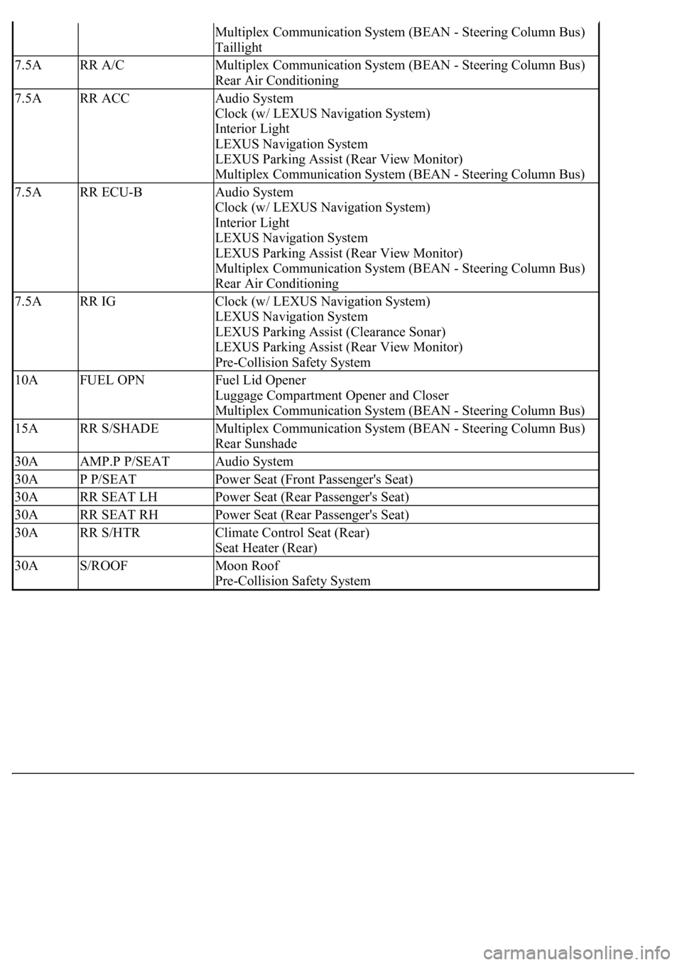
Multiplex Communication System (BEAN - Steering Column Bus)
Taillight
7.5ARR A/CMultiplex Communication System (BEAN - Steering Column Bus)
Rear Air Conditioning
7.5ARR ACCAudio System
Clock (w/ LEXUS Navigation System)
Interior Light
LEXUS Navigation System
LEXUS Parking Assist (Rear View Monitor)
Multiplex Communication System (BEAN - Steering Column Bus)
7.5ARR ECU-BAudio System
Clock (w/ LEXUS Navigation System)
Interior Light
LEXUS Navigation System
LEXUS Parking Assist (Rear View Monitor)
Multiplex Communication System (BEAN - Steering Column Bus)
Rear Air Conditioning
7.5ARR IGClock (w/ LEXUS Navigation System)
LEXUS Navigation System
LEXUS Parking Assist (Clearance Sonar)
LEXUS Parking Assist (Rear View Monitor)
Pre-Collision Safety System
10AFUEL OPNFuel Lid Opener
Luggage Compartment Opener and Closer
Multiplex Communication System (BEAN - Steering Column Bus)
15ARR S/SHADEMultiplex Communication System (BEAN - Steering Column Bus)
Rear Sunshade
30AAMP.P P/SEATAudio System
30AP P/SEATPower Seat (Front Passenger's Seat)
30ARR SEAT LHPower Seat (Rear Passenger's Seat)
30ARR SEAT RHPower Seat (Rear Passenger's Seat)
30ARR S/HTRClimate Control Seat (Rear)
Seat Heater (Rear)
30AS/ROOFMoon Roof
Pre-Collision Safety System
Page 4184 of 4500

registered with the vehicle's garage door opener. After registration, the vehicle's garage door opener can mimic
the signal of the transmitter systems and the original transmitters of each transmitter system are not needed.
1.RESISTER TRANSMITTER CODE
HINT:
The vehicle's garage door opener records transmitter codes for systems such as garage doors, gates,
entry gates, door locks, home lighting systems, security systems or other transmitter code based
systems.
The garage door opener is built into the dome lamp No. 1. If replacing the dome lamp No. 1,
transmitter codes for any systems previously registered in the garage door opener must be re-
registered.
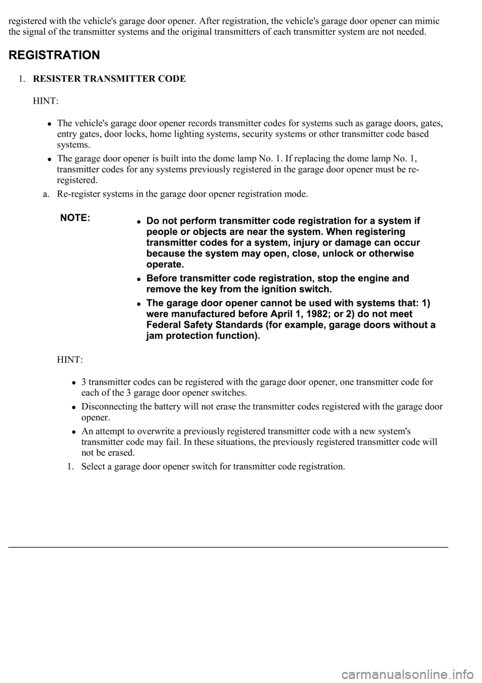
a. Re-register systems in the garage door opener registration mode.
HINT:
3 transmitter codes can be registered with the garage door opener, one transmitter code for
each of the 3 garage door opener switches.
Disconnecting the battery will not erase the transmitter codes registered with the garage door
opener.
An attempt to overwrite a previously registered transmitter code with a new system's
transmitter code may fail. In these situations, the previously registered transmitter code will
not be erased.
1. Select a
garage door opener switch for transmitter code registration.
Page 4252 of 4500
Fig. 66: Checking Water Valve Operation
Courtesy of TOYOTA MOTOR SALES, U.S.A., INC.
35.ADJUST WATER VALVE CONTROL CABLE
a. Turn the ignition switch to the ON position.
b. Disconnect the control cable.
c. Set the temperature control switch to "MAX. COOL".
d. Set the water valve lever to the "COOL" position, connect the control cable and lock the clamp.
HINT:
Lock the clamp while lightly pushing the outer cable in the direction shown in Fig. 67
by an arrow.
Page 4278 of 4500
Fig. 90: Removing Smog Ventilation Sensor Bolt
Courtesy of TOYOTA MOTOR SALES, U.S.A., INC.
10.REMOVE HOOD LOCK ASSY
a. Remove the 2 bolts, nut and hood lock ass
y.
Page 4279 of 4500
Fig. 91: Removing Hood Lock Assy
Courtesy of TOYOTA MOTOR SALES, U.S.A., INC.
11.REMOVE RADIATOR SUPPORT SUB-ASSY UPPER
a. Remove the 2 nuts and 2 radiator brackets.
Page 4295 of 4500
INSPECTION
1.INSPECT REAR BLOWER MOTOR CIRCUIT (See REAR BLOWER MOTOR CIRCUIT
)
2.EXHAUST DAMPER CONTROL SERVOMOTOR CIRCUIT (See EXHAUST DAMPER
CONTROL SERVOMOTOR CIRCUIT )
3.INSPECT REAR MAGNETIC VALVE CIRCUIT (See REAR MAGNETIC VALVE CIRCUIT
)
4.INSPECT SMOKE SENSOR CIRCUIT (See SMOKE SENSOR CIRCUIT
)
5.INSPECT EVAPORATOR SUB-ASSY (REAR)
a. Check the evaporator sub-assy (rear) fins for blockage.
If the fins are clogged, clean them with compressed air.
b. Check the fitting for cracks or scratches.
If necessary, repair or replace.
6.INSPECT COOLING BOX LAMP SUB-ASSY
a. Connect positive (+) lead to terminal 1 and negative (-) lead to terminal 2.
b. Check that the cooling box lamp sub-assy comes on.
If coolin
g box light does not come on, replace the cooling box lamp sub-assy.
Page 4358 of 4500
Fig. 10: Removing Outer Mirror Switch Assy
Courtesy of TOYOTA MOTOR SALES, U.S.A., INC.
19.REMOVE INSTRUMENT PANEL SAFETY PAD SUB-ASSY NO.1
a. Remove the 2 bolts and the screw < N >.
b. Remove the 2 bolts < D > and the hood lock control cable assy.
c. Disengage the 4 clips and remove the instrument panel safety pad sub-assy No.1.
d. Disconnect the connectors.
Page 4369 of 4500
tape up the screwdriver tip before use.
c. Disconnect the connectors.
33.REMOVE FRONT PILLAR GARNISH LH (SEE REPLACEMENT
)
34.REMOVE FRONT PILLAR GARNISH RH (SEE REPLACEMENT
)
35.REMOVE FRONT DOOR SCUFF PLATE LH (SEE REPLACEMENT
)
36.REMOVE FRONT DOOR SCUFF PLATE RH (SEE REPLACEMENT
)
37.REMOVE SHIFT LEVER KNOB SUB-ASSY
a. turn the shift lever knob sub-assy counterclockwise and remove the shift lever knob sub-assy.
Fig. 21: Removing Shift Lever Knob Sub
-Assy
Courtesy of TOYOTA MOTOR SALES, U.S.A., INC.
38.REMOVE CONSOLE PANEL SUB-ASSY UPPER
a. Using a moulding remover, disengage the 4 clips and remove the console panel sub-assy upper.
HINt:
Use a screwdriver if a moulding remover is not available.
tape up the screwdriver tip before use.