2003 LEXUS LS430 coolant temperature
[x] Cancel search: coolant temperaturePage 2679 of 4500
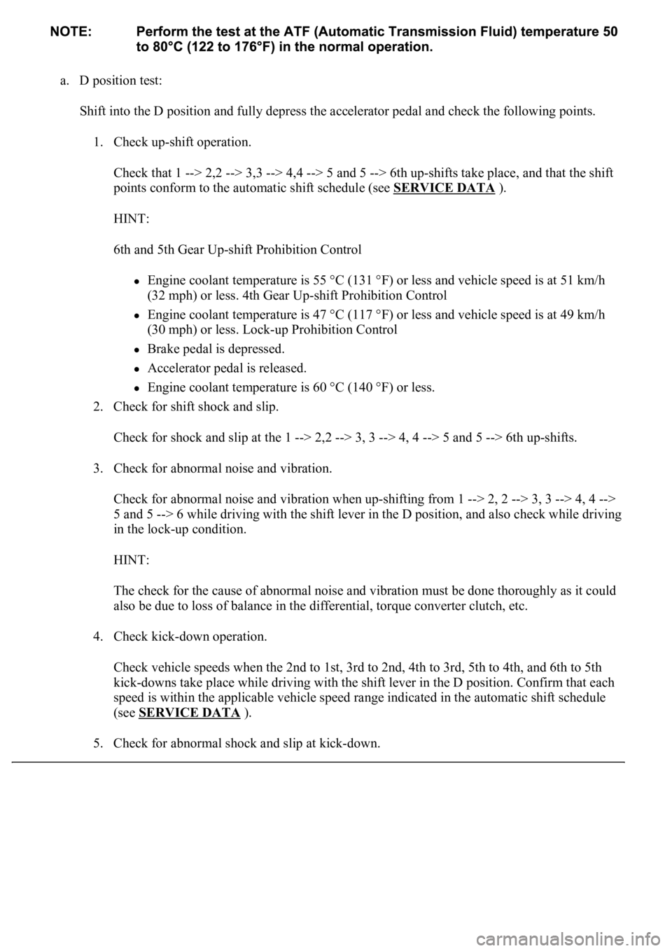
a. D position test:
Shift into the D position and fully depress the accelerator pedal and check the following points.
1. Check up-shift operation.
Check that 1 --> 2,2 --> 3,3 --> 4,4 --> 5 and 5 --> 6th up-shifts take place, and that the shift
points conform to the automatic shift schedule (see SERVICE DATA
).
HINT:
6th and 5th Gear Up-shift Prohibition Control
Engine coolant temperature is 55 °C (131 °F) or less and vehicle speed is at 51 km/h
(32 mph) or less. 4th Gear Up-shift Prohibition Control
Engine coolant temperature is 47 °C (117 °F) or less and vehicle speed is at 49 km/h
(30 mph) or less. Lock-up Prohibition Control
Brake pedal is depressed.
Accelerator pedal is released.
<00280051004a004c005100480003004600520052004f0044005100570003005700480050005300480055004400570058005500480003004c00560003001900130003008300260003000b001400170013000300830029000c0003005200550003004f004800
560056001100030003[
2. Check for shift shock and slip.
Check for shock and slip at the 1 --> 2,2 --> 3, 3 --> 4, 4 --> 5 and 5 --> 6th up-shifts.
3. Check for abnormal noise and vibration.
Check for abnormal noise and vibration when up-shifting from 1 --> 2, 2 --> 3, 3 --> 4, 4 -->
5 and 5 --> 6 while driving with the shift lever in the D position, and also check while driving
in the lock-up condition.
HINT:
The check for the cause of abnormal noise and vibration must be done thoroughly as it could
also be due to loss of balance in the differential, torque converter clutch, etc.
4. Check kick-down operation.
<0026004b00480046004e000300590048004b004c0046004f004800030056005300480048004700560003005a004b0048005100030057004b004800030015005100470003005700520003001400560057000f00030016005500470003005700520003001500
510047000f000300170057004b000300570052000300160055[d, 5th to 4th, and 6th to 5th
kick-downs take place while driving with the shift lever in the D position. Confirm that each
speed is within the applicable vehicle speed range indicated in the automatic shift schedule
(see SERVICE DATA
).
5. Check for abnormal shock and slip at kic
k-down.
Page 2695 of 4500
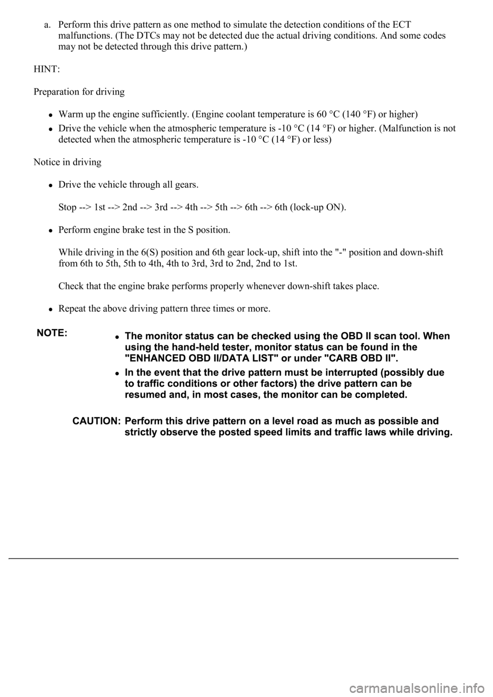
a. Perform this drive pattern as one method to simulate the detection conditions of the ECT
malfunctions. (The DTCs may not be detected due the actual driving conditions. And some codes
may not be detected through this drive pattern.)
HINT:
Preparation for driving
Warm up the engine sufficiently. (Engine coolant temperature is 60 °C (140 °F) or higher)
Drive the vehicle when the atmospheric temperature is -10 °C (14 °F) or higher. (Malfunction is not
detected when the atmospheric temperature is -10 °C (14 °F) or less)
Notice in driving
Drive the vehicle through all gears.
Stop --> 1st --> 2nd --> 3rd --> 4th --> 5th --> 6th --> 6th (lock-up ON).
Perform engine brake test in the S position.
While driving in the 6(S) position and 6th gear lock-up, shift into the "-" position and down-shift
<0049005500520050000300190057004b000300570052000300180057004b000f000300180057004b000300570052000300170057004b000f000300170057004b0003005700520003001600550047000f000300160055004700030057005200030015005100
47000f00030015005100470003005700520003001400560057[.
<0026004b00480046004e00030057004b0044005700030057004b0048000300480051004a004c005100480003004500550044004e00480003005300480055004900520055005000560003005300550052005300480055004f005c0003005a004b0048005100
48005900480055000300470052005a005100100056004b004c[ft takes place.
Repeat the above driving pattern three times or more.
Page 2712 of 4500
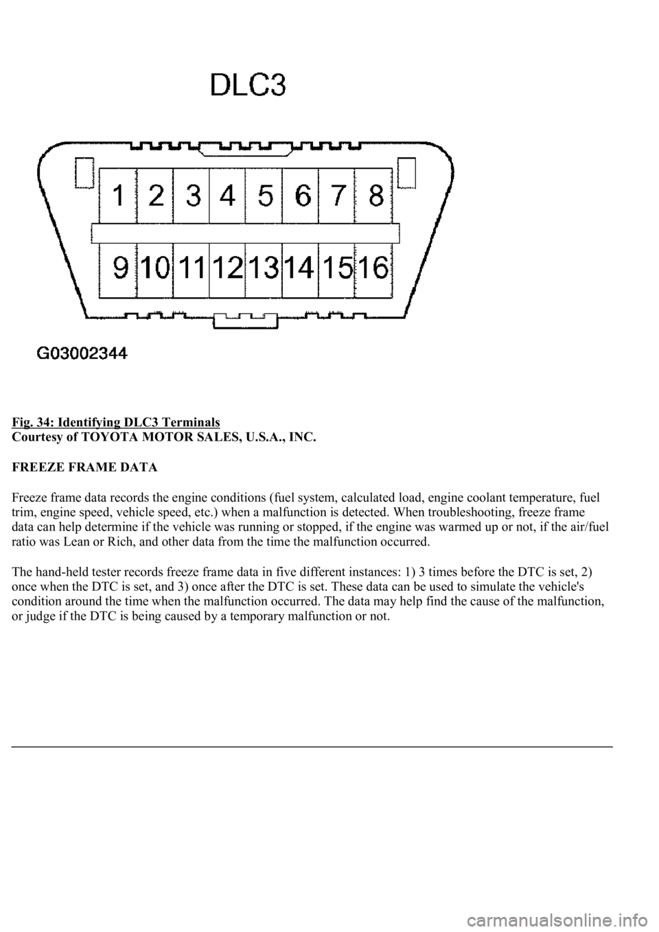
Fig. 34: Identifying DLC3 Terminals
Courtesy of TOYOTA MOTOR SALES, U.S.A., INC.
FREEZE FRAME DATA
Freeze frame data records the engine conditions (fuel system, calculated load, engine coolant temperature, fuel
trim, engine speed, vehicle speed, etc.) when a malfunction is detected. When troubleshooting, freeze frame
data can help determine if the vehicle was running or stopped, if the engine was warmed up or not, if the air/fuel
ratio was Lean or Rich, and other data from the time the malfunction occurred.
The hand-held tester records freeze frame data in five different instances: 1) 3 times before the DTC is set, 2)
once when the DTC is set, and 3) once after the DTC is set. These data can be used to simulate the vehicle's
condition around the time when the malfunction occurred. The data may help find the cause of the malfunction,
or
judge if the DTC is being caused by a temporary malfunction or not.
Page 2749 of 4500
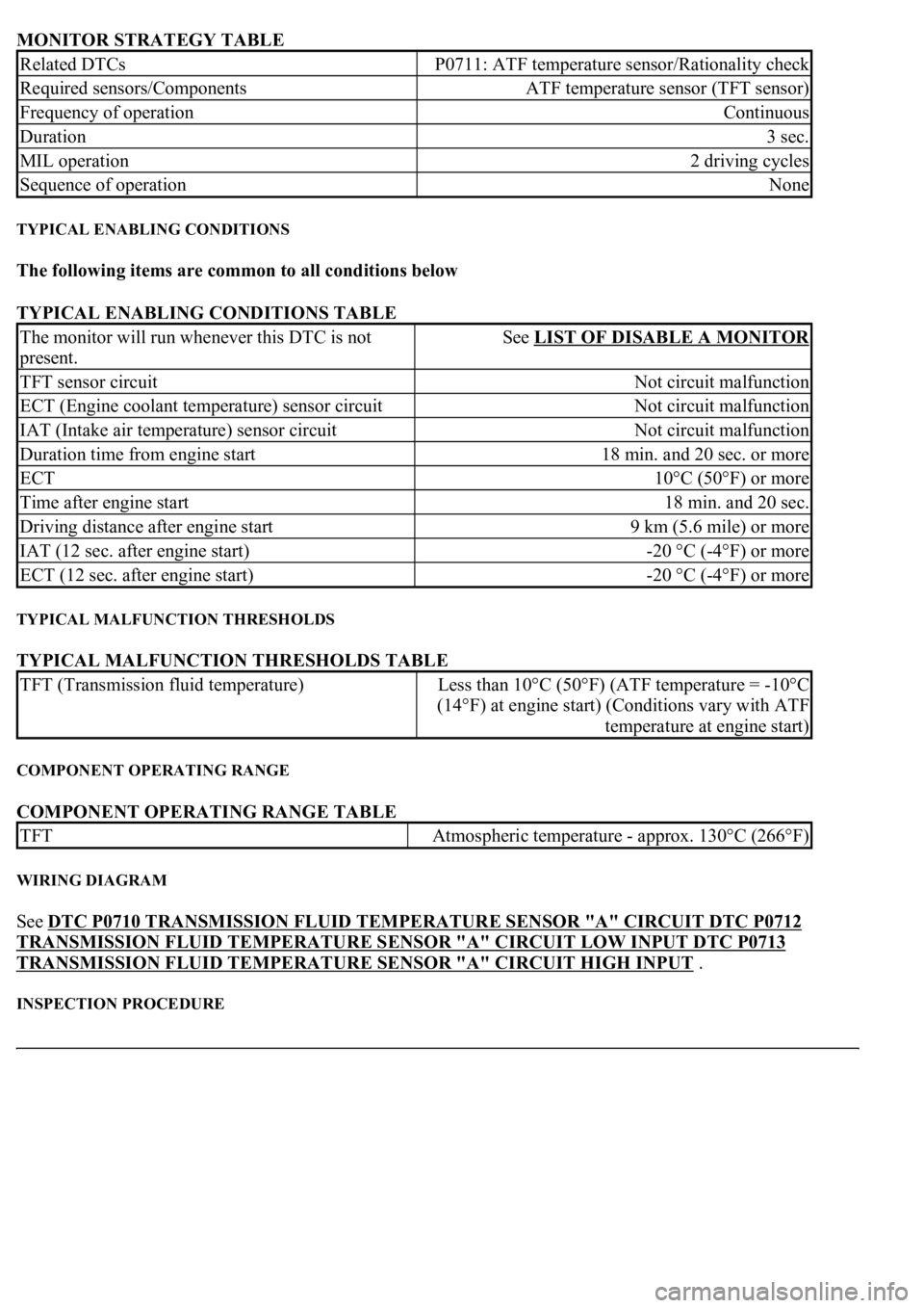
MONITOR STRATEGY TABLE
TYPICAL ENABLING CONDITIONS
The following items are common to all conditions below
TYPICAL ENABLING CONDITIONS TABLE
TYPICAL MALFUNCTION THRESHOLDS
TYPICAL MALFUNCTION THRESHOLDS TABLE
COMPONENT OPERATING RANGE
COMPONENT OPERATING RANGE TABLE
WIRING DIAGRAM
See DTC P0710 TRANSMISSION FLUID TEMPERATURE SENSOR "A" CIRCUIT DTC P0712
TRANSMISSION FLUID TEMPERATURE SENSOR "A" CIRCUIT LOW INPUT DTC P0713
TRANSMISSION FLUID TEMPERATURE SENSOR "A" CIRCUIT HIGH INPUT .
INSPECTION PROCEDURE
Related DTCsP0711: ATF temperature sensor/Rationality check
Required sensors/ComponentsATF temperature sensor (TFT sensor)
Frequency of operationContinuous
Duration3 sec.
MIL operation2 driving cycles
Sequence of operationNone
The monitor will run whenever this DTC is not
present.See LIST OF DISABLE A MONITOR
TFT sensor circuitNot circuit malfunction
ECT (Engine coolant temperature) sensor circuitNot circuit malfunction
IAT (Intake air temperature) sensor circuitNot circuit malfunction
Duration time from engine start18 min. and 20 sec. or more
ECT10°C (50°F) or more
Time after engine start18 min. and 20 sec.
Driving distance after engine start9 km (5.6 mile) or more
IAT (12 sec. after engine start)-20 °C (-4°F) or more
ECT (12 sec. after engine start)-20 °C (-4°F) or more
TFT (Transmission fluid temperature)Less than 10°C (50°F) (ATF temperature = -10°C
(14°F) at engine start) (Conditions vary with ATF
temperature at engine start)
TFTAtmospheric temperature - approx. 130°C (266°F)
Page 2766 of 4500
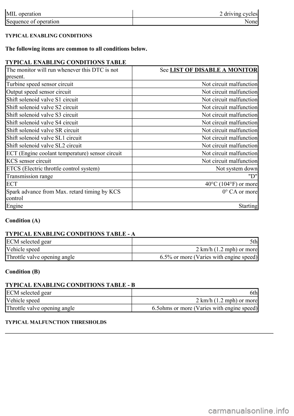
TYPICAL ENABLING CONDITIONS
The following items are common to all conditions below.
TYPICAL ENABLING CONDITIONS TABLE
Condition (A)
TYPICAL ENABLING CONDITIONS TABLE - A
Condition (B)
TYPICAL ENABLING CONDITIONS TABLE - B
TYPICAL MALFUNCTION THRESHOLDS
MIL operation2 driving cycles
Sequence of operationNone
The monitor will run whenever this DTC is not
present.See LIST OF DISABLE A MONITOR
Turbine speed sensor circuitNot circuit malfunction
Output speed sensor circuitNot circuit malfunction
Shift solenoid valve S1 circuitNot circuit malfunction
Shift solenoid valve S2 circuitNot circuit malfunction
Shift solenoid valve S3 circuitNot circuit malfunction
Shift solenoid valve S4 circuitNot circuit malfunction
Shift solenoid valve SR circuitNot circuit malfunction
Shift solenoid valve SL1 circuitNot circuit malfunction
Shift solenoid valve SL2 circuitNot circuit malfunction
ECT (Engine coolant temperature) sensor circuitNot circuit malfunction
KCS sensor circuitNot circuit malfunction
ETCS (Electric throttle control system)Not system down
Transmission range"D"
ECT40°C (104°F) or more
Spark advance from Max. retard timing by KCS
control0° CA or more
EngineStarting
ECM selected gear5th
Vehicle speed2 km/h (1.2 mph) or more
Throttle valve opening angle6.5% or more (Varies with engine speed)
ECM selected gear6th
Vehicle speed2 km/h (1.2 mph) or more
Throttle valve opening angle6.5ohms or more (Varies with engine speed)
Page 2778 of 4500
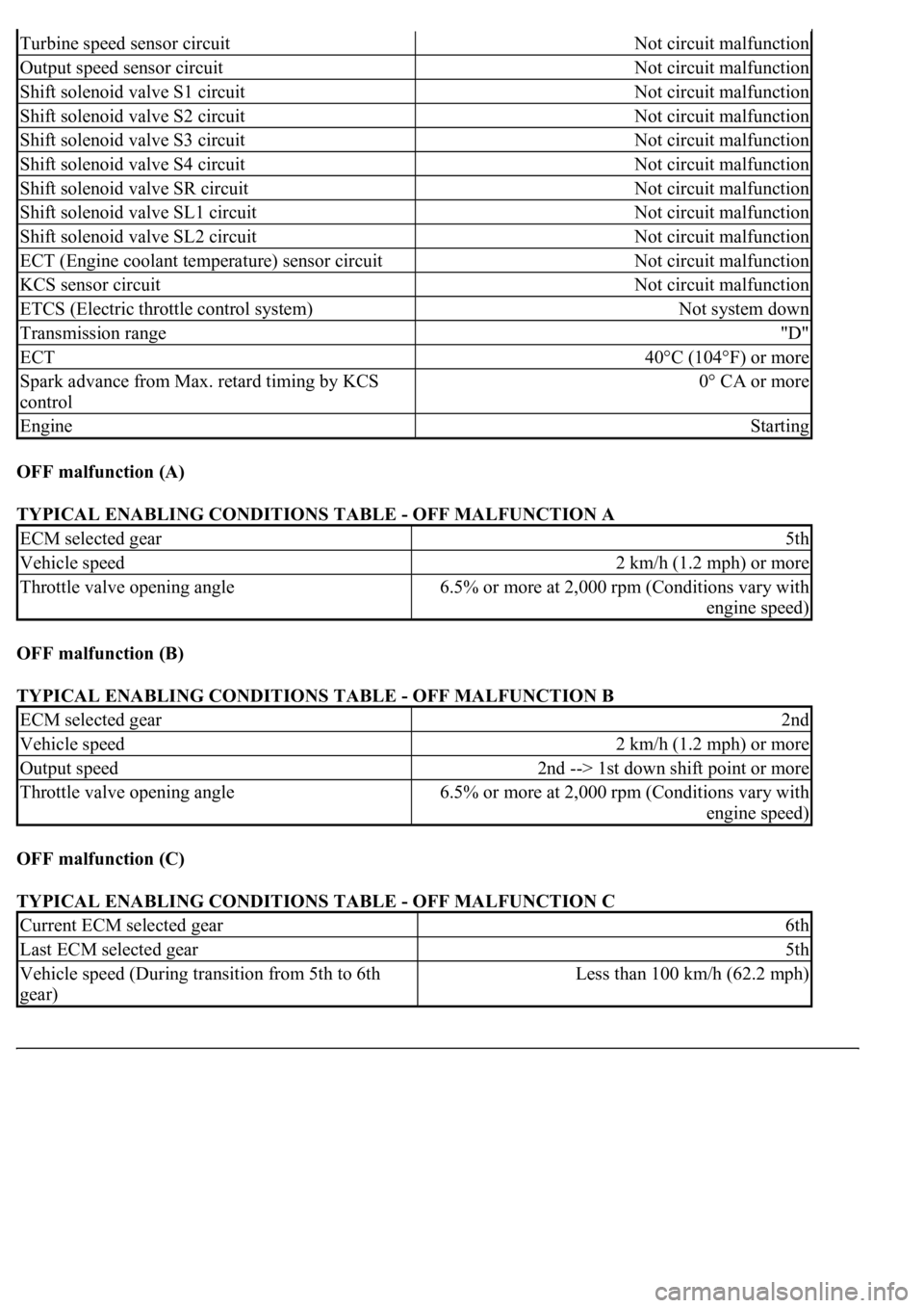
OFF malfunction (A)
TYPICAL ENABLING CONDITIONS TABLE - OFF MALFUNCTION A
OFF malfunction (B)
TYPICAL ENABLING CONDITIONS TABLE - OFF MALFUNCTION B
OFF malfunction (C)
TYPICAL ENABLING CONDITIONS TABLE - OFF MALFUNCTION C
Turbine speed sensor circuitNot circuit malfunction
Output speed sensor circuitNot circuit malfunction
Shift solenoid valve S1 circuitNot circuit malfunction
Shift solenoid valve S2 circuitNot circuit malfunction
Shift solenoid valve S3 circuitNot circuit malfunction
Shift solenoid valve S4 circuitNot circuit malfunction
Shift solenoid valve SR circuitNot circuit malfunction
Shift solenoid valve SL1 circuitNot circuit malfunction
Shift solenoid valve SL2 circuitNot circuit malfunction
ECT (Engine coolant temperature) sensor circuitNot circuit malfunction
KCS sensor circuitNot circuit malfunction
ETCS (Electric throttle control system)Not system down
Transmission range"D"
ECT40°C (104°F) or more
Spark advance from Max. retard timing by KCS
control0° CA or more
EngineStarting
ECM selected gear5th
Vehicle speed2 km/h (1.2 mph) or more
Throttle valve opening angle6.5% or more at 2,000 rpm (Conditions vary with
engine speed)
ECM selected gear2nd
Vehicle speed2 km/h (1.2 mph) or more
Output speed2nd --> 1st down shift point or more
Throttle valve opening angle6.5% or more at 2,000 rpm (Conditions vary with
engine speed)
Current ECM selected gear6th
Last ECM selected gear5th
Vehicle speed (During transition from 5th to 6th
gear)Less than 100 km/h (62.2 mph)
Page 2786 of 4500
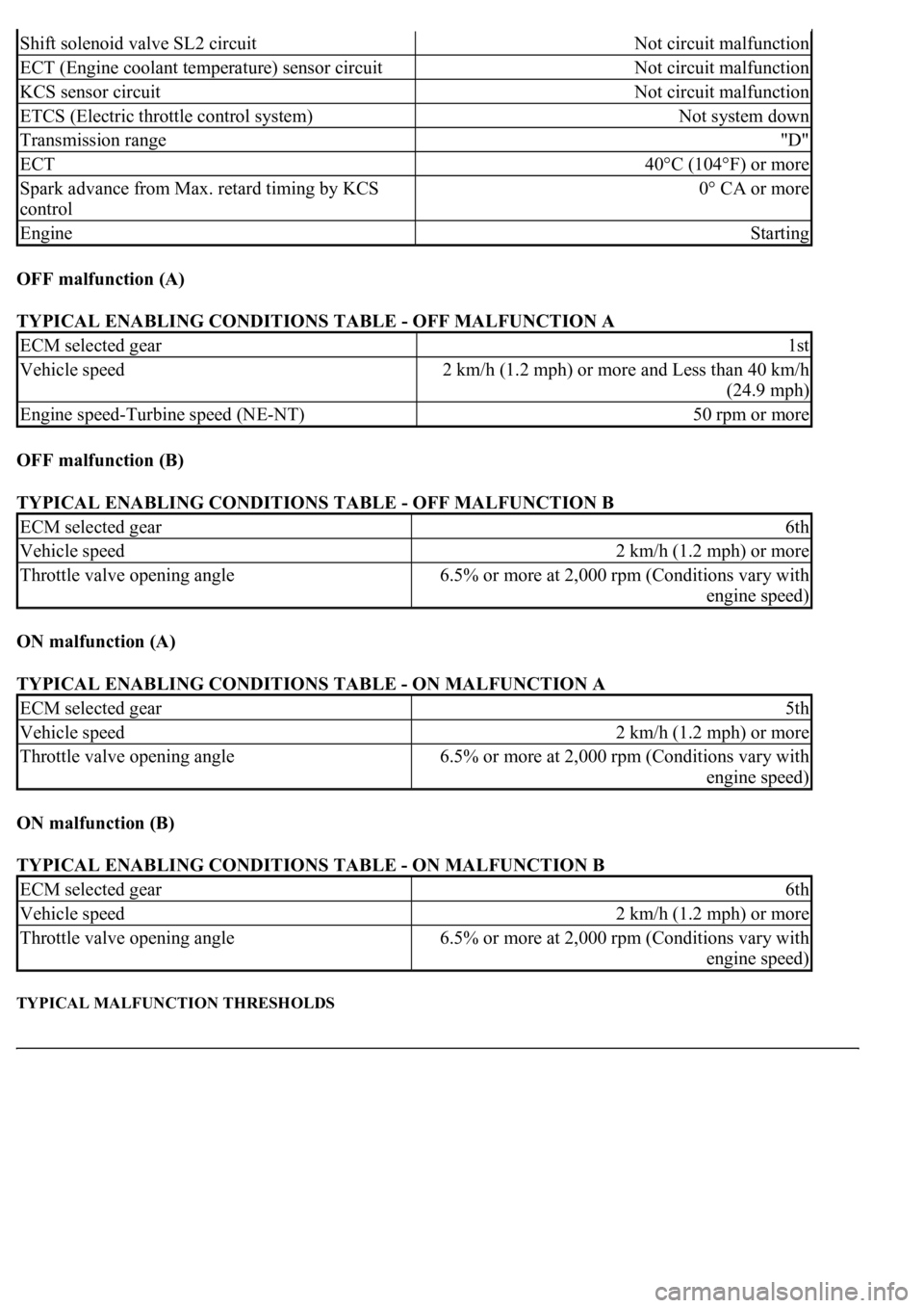
OFF malfunction (A)
TYPICAL ENABLING CONDITIONS TABLE - OFF MALFUNCTION A
OFF malfunction (B)
TYPICAL ENABLING CONDITIONS TABLE - OFF MALFUNCTION B
ON malfunction (A)
TYPICAL ENABLING CONDITIONS TABLE - ON MALFUNCTION A
ON malfunction (B)
TYPICAL ENABLING CONDITIONS TABLE - ON MALFUNCTION B
TYPICAL MALFUNCTION THRESHOLDS
Shift solenoid valve SL2 circuitNot circuit malfunction
ECT (Engine coolant temperature) sensor circuitNot circuit malfunction
KCS sensor circuitNot circuit malfunction
ETCS (Electric throttle control system)Not system down
Transmission range"D"
ECT40°C (104°F) or more
Spark advance from Max. retard timing by KCS
control0° CA or more
EngineStarting
ECM selected gear1st
Vehicle speed2 km/h (1.2 mph) or more and Less than 40 km/h
(24.9 mph)
Engine speed-Turbine speed (NE-NT)50 rpm or more
ECM selected gear6th
Vehicle speed2 km/h (1.2 mph) or more
Throttle valve opening angle6.5% or more at 2,000 rpm (Conditions vary with
engine speed)
ECM selected gear5th
Vehicle speed2 km/h (1.2 mph) or more
Throttle valve opening angle6.5% or more at 2,000 rpm (Conditions vary with
engine speed)
ECM selected gear6th
Vehicle speed2 km/h (1.2 mph) or more
Throttle valve opening angle6.5% or more at 2,000 rpm (Conditions vary with
engine speed)
Page 2793 of 4500
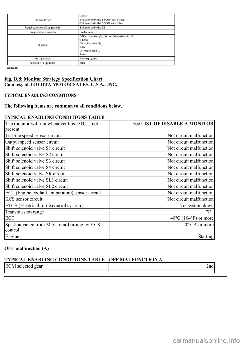
Fig. 108: Monitor Strategy Specification Chart
Courtesy of TOYOTA MOTOR SALES, U.S.A., INC.
TYPICAL ENABLING CONDITIONS
The following items are common to all conditions below.
TYPICAL ENABLING CONDITIONS TABLE
OFF malfunction (A)
TYPICAL ENABLING CONDITIONS TABLE - OFF MALFUNCTION A
The monitor will run whenever this DTC is not
present.See LIST OF DISABLE A MONITOR
Turbine speed sensor circuitNot circuit malfunction
Output speed sensor circuitNot circuit malfunction
Shift solenoid valve S1 circuitNot circuit malfunction
Shift solenoid valve S2 circuitNot circuit malfunction
Shift solenoid valve S3 circuitNot circuit malfunction
Shift solenoid valve S4 circuitNot circuit malfunction
Shift solenoid valve SR circuitNot circuit malfunction
Shift solenoid valve SL1 circuitNot circuit malfunction
Shift solenoid valve SL2 circuitNot circuit malfunction
ECT (Engine coolant temperature) sensor circuitNot circuit malfunction
KCS sensor circuitNot circuit malfunction
ETCS (Electric throttle control system)Not system down
Transmission range"D"
ECT40°C (104°F) or more
Spark advance from Max. retard timing by KCS
control0° CA or more
EngineStarting
ECM selected gear2nd