Page 390 of 4500

a. Connect the hand-held tester to the DLC3.
b. Turn the ignition switch to the ON position and push the hand-held tester main switch on.
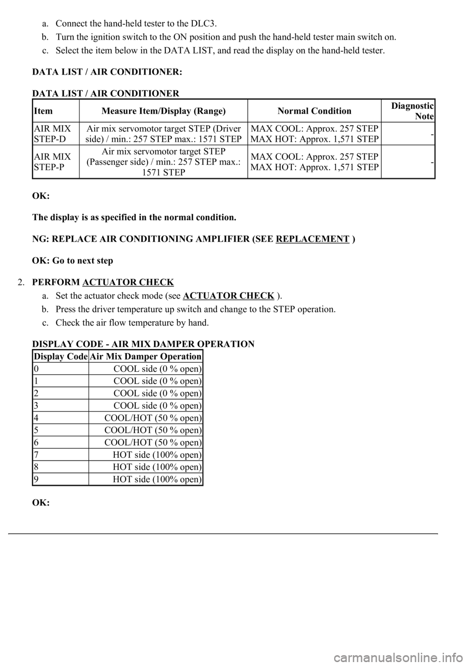
c. Select the item below in the DATA LIST, and read the display on the hand-held tester.
DATA LIST / AIR CONDITIONER:
DATA LIST / AIR CONDITIONER
OK:
The display is as specified in the normal condition.
NG: REPLACE AIR CONDITIONING AMPLIFIER (SEE REPLACEMENT
)
OK: Go to next step
2.PERFORM ACTUATOR CHECK
a. Set the actuator check mode (see ACTUATOR CHECK
).
b. Press the driver temperature up switch and change to the STEP operation.
c. Check the air flow temperature by hand.
DISPLAY CODE - AIR MIX DAMPER OPERATION
OK:
ItemMeasure Item/Display (Range)Normal ConditionDiagnostic
Note
AIR MIX
STEP-DAir mix servomotor target STEP (Driver
side) / min.: 257 STEP max.: 1571 STEPMAX COOL: Approx. 257 STEP
MAX HOT: Approx. 1,571 STEP-
AIR MIX
STEP-PAir mix servomotor target STEP
(Passenger side) / min.: 257 STEP max.:
1571 STEPMAX COOL: Approx. 257 STEP
MAX HOT: Approx. 1,571 STEP-
Display CodeAir Mix Damper Operation
0COOL side (0 % open)
1COOL side (0 % open)
2COOL side (0 % open)
3COOL side (0 % open)
4COOL/HOT (50 % open)
5COOL/HOT (50 % open)
6COOL/HOT (50 % open)
7HOT side (100% open)
8HOT side (100% open)
9HOT side (100% open)
Page 391 of 4500
Air flow temperature changes in accordance with each display code.
NG: REPLACE AIR CONDITIONING AMPLIFIER (SEE REPLACEMENT
)
OK: Go to next step
3.INSPECT AIR MIX CONTROL SERVOMOTOR
a. Remove the air mix control servomotor.
b. Measure the resistance according to the value (s) in the table below:
Standard: (Driver side)
AIR MIX CONTROL SERVOMOTOR RESISTANCE (DRIVER'S SIDE)
Tester connectionConditionSpecified condition
A42-1 (AMDr1) -A42-4 (AMDB)Always24.3 to 26.3 ohms
A42-2 (AMDr2) -A42-4 (AMDB)Always24.3 to 26.3 ohms
A42-5 (AMDr3) -A42-4 (AMDB)Always24.3 to 26.3 ohms
A42-6 (AMDr4) -A42-4 (AMDB)Always24.3 to 26.3 ohms
Page 395 of 4500
Courtesy of TOYOTA MOTOR SALES, U.S.A., INC.
NG: REPLACE AIR MIX CONTROL SERVOMOTOR
OK: Go to next step
4.CHECK HARNESS AND CONNECTOR (AIR MIX CONTROL SERVOMOTOR - AIR
CONDITIONING AMPLIFIER) (SEE ELECTRONIC CIRCUIT INSPECTION PROCEDURE
)
a. Measure the resistance according to the value (s) in the table below.
Standard (Driver side):
AIR MIX CONTROL SERVOMOTOR - AIR CONDITIONING AMPLIFIER RESISTANCE
(DRIVER'S SIDE)
Tester connectionConditionSpecified condition
A37-1 (AMDr1) -A42-6AlwaysBelow 1 ohms
A37-2 (AMDr2) -A42-5AlwaysBelow 1 ohms
A37-3 (AMDr3) -A42-2AlwaysBelow 1 ohms
A37-4 (AMDr4) -A42-1AlwaysBelow 1 ohms
A37-10 (AMDB) - A42-4AlwaysBelow 1 ohms
A37-1 (AMDr1) - Body groundAlways10 kohms or higher
A37-2 (AMDr2) - Body groundAlways10 kohms or higher
A37-3 (AMDr3) - Body groundAlways10 kohms or higher
A37-4 (AMDr4) - Body groundAlways10 kohms or higher
A37-10 (AMDB) - Body groundAlways10 kohms or higher
Page 396 of 4500
Fig. 144: Checking Harness And Connector (Air Mix Control Servomotor - Air Conditioning
Amplifier) (Driver'S Side)
Page 397 of 4500
Courtesy of TOYOTA MOTOR SALES, U.S.A., INC.
Standard (Passenger side):
AIR MIX CONTROL SERVOMOTOR - AIR CONDITIONING AMPLIFIER RESISTANCE
(PASSENGER SIDE)
Tester connectionConditionSpecified condition
A36-1 (AMPa1) -A43-6AlwaysBelow 1 ohms
A36-2 (AMPa2) -A43-5AlwaysBelow 1 ohms
A36-3 (AMPa3) -A43-2AlwaysBelow 1 ohms
A36-4 (AMPa4) -A43-1AlwaysBelow 1 ohms
A36-13 (AMPB) - A43-4AlwaysBelow 1 ohms
A36-1 (AMPa1) - Body groundAlways10 kohms or higher
A36-2 (AMPa2) - Body groundAlways10 kohms or higher
A36-3 (AMPa3) - Body groundAlways10 kohms or higher
A36-4 (AMPa4) - Body groundAlways10 kohms or higher
A36-13 (AMPB) - Body groundAlways10 kohms or higher
Page 398 of 4500
Fig. 145: Checking Harness And Connector (Air Mix Control Servomotor - Air Conditioning
Amplifier) (Passenger Side)
Page 399 of 4500
Courtesy of TOYOTA MOTOR SALES, U.S.A., INC.
NG: REPAIR OR REPLACE HARNESS OR / CONNECTOR
OK: REPLACE AIR CONDITIONING AMPLIFIER (SEE REPLACEMENT
)
CIRCUIT DESCRIPTION
This is the back-up power source circuit for the A/C amplifier. Power is supplied even when turning the ignition
switch off and is used for diagnostic trouble code memory, etc.
WIRING DIAGRAM
Fig. 146: Back
-Up Power Source Circuit
Page 401 of 4500
Fig. 147: Identifying Location Of Fuse (A/C)
Courtesy of TOYOTA MOTOR SALES, U.S.A., INC.
OK: Go to next step
3.INSPECT AIR CONDITIONING AMPLIFIER (B - BODY GROUND)
a. Remove the A/C amplifier assy and disconnect the connector.
b. Measure the voltage according to the value (s) in the table below.
Standard:
AIR CONDITIONING AMPLIFIER (B - BODY GROUND) VOLTAGE
NG: REPAIR OR REPLACE WIRE HARNESS (AIR CONDITIONING AMPLIFIER -
BATTERY)
Tester connectionConditionSpecified condition
A11-21 (+B) - Body groundAlways10 to 14 V