Page 210 of 4500

Fig. 6: Air Conditioning System Diagram (2 Of 2)
Courtesy of TOYOTA MOTOR SALES, U.S.A., INC.
1.GENERAL
a. The air conditioning system has the following features:
In compliance with the temperature set at the temperature control switch, the neural network
control calculates the outlet temperature based on the input signals from various sensors. In
addition, corrections in accordance with the signals from the evaporative temperature sensor
and the water temperature sensor are added to control the outlet air temperature.
Controls the front and rear blower motors in accordance with the airflow volume that has
been calculated by the neural network control based on the input signals from various
sensors.
Automatically switches the outlets in accordance with the outlet mode ratio that has been
calculated by the neural network control based on the input signals from various sensors.
Automatically controls the air inlet control damper in accordance with the airflow volume
that has been calculated by the neural network control.
Turns the compressor on/off and controls the discharge capacity based on the signals from
various sensors.
Based on the signals from the ambient temperature sensor, this control calculates the outside
temperature, which is then corrected in the air conditioner ECU, and shown in the multi-
information display in the combination meter.
Switched the rear defogger and outside rear view mirror heaters on for 15 minutes when the
rear defogger switch is switched on. Switched them off if the switch is pressed while they are
operating.
Controls the orientation and the angle of the front center register based on the input signals
from various sensors and on the outlet mode.
Determines whether the clean air filter (for the front A/C) is clogged by monitoring the air
inlets, and airflow volume.
The A/C amplifier automatically controls the air inlets based on the signals from the smog
ventilation sensor.
Improves the air quality by linking the air inlet control damper and the blower motor (for the
rear A/C and air purifier), based on the signals from the exhaust gas sensor and the smoke
sensor.
Checks the sensors in accordance with operation of the air conditioner switches.
2.MODEL POSITION AND DAMPER OPERATION
Page 3032 of 4500
Fig. 48: Removing Remaining Tape On Door Side
Courtesy of TOYOTA MOTOR SALES, U.S.A., INC.
7.REMOVE OUTER REAR VIEW MIRROR ASSY LH
a. Disconnect the connector.
b. Remove the 3 bolts and mirror.
Page 3033 of 4500
Fig. 49: Removing Outer Rear View Mirror Assy LH
Courtesy of TOYOTA MOTOR SALES, U.S.A., INC.
8.REMOVE FRONT DOOR ECU
a. Disconnect the connector.
b. Remove the 2 screws and ECU.
9.REMOVE FRONT NO.1 SPEAKER ASSY (See REPLACEMENT
)
10.REMOVE FRONT DOOR BELT MOULDING ASSY LH (See REPLACEMENT
)
11.REMOVE FRONT DOOR WINDOW FRAME MOULDING REAR LH (See REPLACEMENT
)
12.REMOVE FRONT DOOR WINDOW FRAME MOULDING FRONT LH (See REPLACEMENT
)
13.REMOVE FRONT DOOR GLASS RUN LH
a. Using a drill of less than +/- 4 mm (0.16 in.), drill out the heads of the 5 rivets and remove the glass
run.
Page 3068 of 4500
Fig. 81: Connecting Speaker Connector
Courtesy of TOYOTA MOTOR SALES, U.S.A., INC.
36.INSTALL OUTER REAR VIEW MIRROR ASSY LH
a. Install the mirror with the 3 bolts.
Torque: 5.5 N.m (56 kgf.cm, 49 in..lbf)
b. Connect the mirror connector.
Page 3853 of 4500
4.REMOVE DOOR FRAME GARNISH LH (See step 5 in OVERHAUL )
5.REMOVE OUTER REAR VIEW MIRROR ASSY LH (See step 7 on OVERHAUL
)
6.REMOVE FRONT DOOR BELT MOLDING ASSY LH
a. Put protective tape under the molding.
b. Remove the screw.
c. Using a molding remover, pry out the molding as shown in Fig. 67
.
HINT:
Tape the remover tip before use.
Page 3903 of 4500
Open the control switch box.
b. w/o LEXUS link system:
Open the upper console.
c. Using a screwdriver, pry out the lens.
HINT:
Tape the screwdriver tip before use.
d. Remove the 4 screws and map lamp, and then disconnect the connectors.
Fig. 113: Removing Map Lamp Assy
Courtesy of TOYOTA MOTOR SALES, U.S.A., INC.
33.REMOVE INNER REAR VIEW MIRROR ASSY
a. Remove the 2 screws and mirror.
Page 3904 of 4500
b. Disengage the connector from the body.
c. Disconnect the connector.
Fig. 114: Removing Inner Rear View Mirror Assy
Courtesy of TOYOTA MOTOR SALES, U.S.A., INC.
34.REMOVE VISOR HOLDER
a. Remove the screw and visor holder.
Page 4163 of 4500

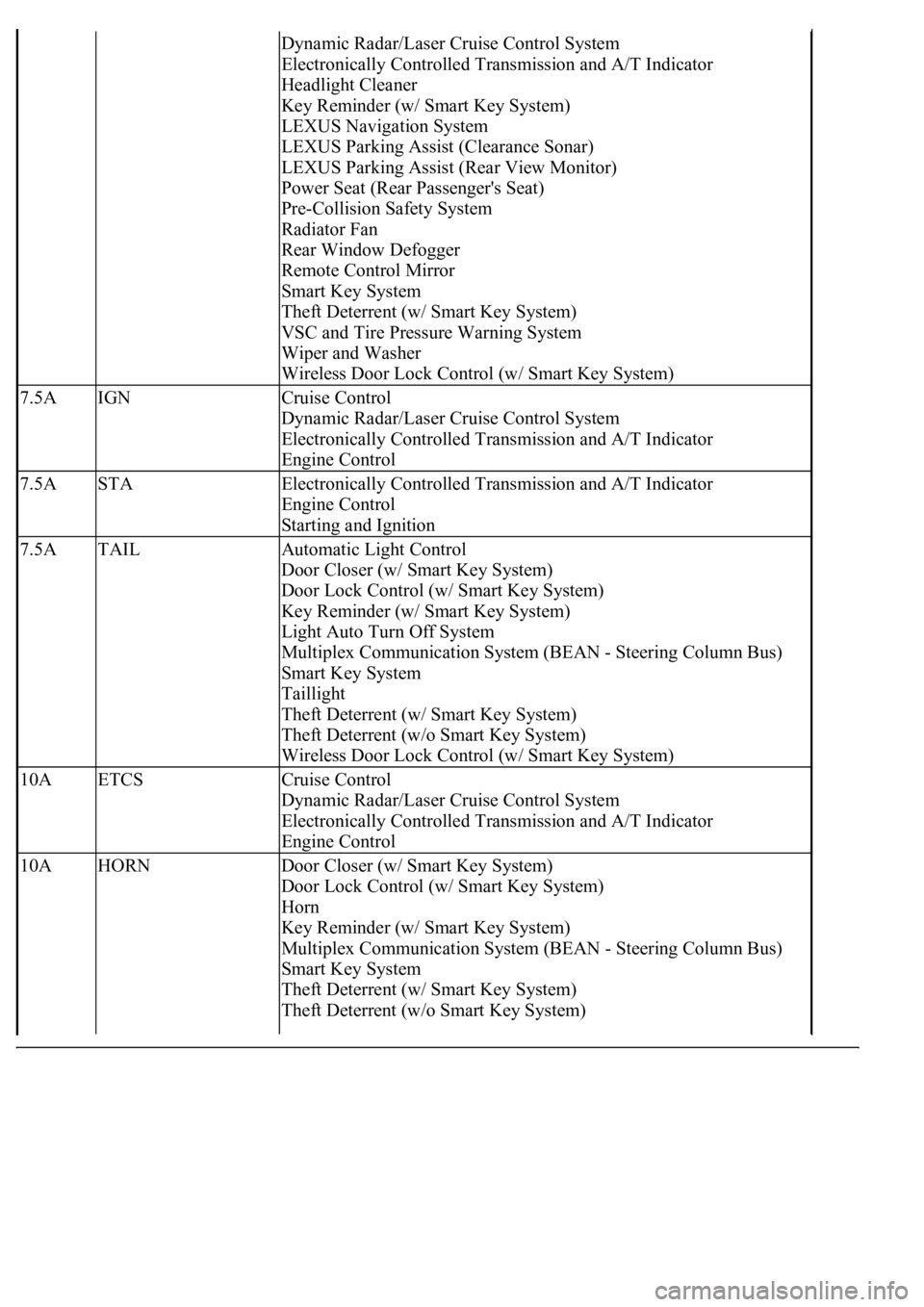
Dynamic Radar/Laser Cruise Control System
Electronically Controlled Transmission and A/T Indicator
Headlight Cleaner
Key Reminder (w/ Smart Key System)
LEXUS Navigation System
LEXUS Parking Assist (Clearance Sonar)
LEXUS Parking Assist (Rear View Monitor)
Power Seat (Rear Passenger's Seat)
Pre-Collision Safety System
Radiator Fan
Rear Window Defogger
Remote Control Mirror
Smart Key System
Theft Deterrent (w/ Smart Key System)
VSC and Tire Pressure Warning System
Wiper and Washer
Wireless Door Lock Control (w/ Smart Key System)
7.5AIGNCruise Control
Dynamic Radar/Laser Cruise Control System
Electronically Controlled Transmission and A/T Indicator
Engine Control
7.5ASTAElectronically Controlled Transmission and A/T Indicator
Engine Control
Starting and Ignition
7.5ATAILAutomatic Light Control
Door Closer (w/ Smart Key System)
Door Lock Control (w/ Smart Key System)
Key Reminder (w/ Smart Key System)
Light Auto Turn Off System
Multiplex Communication System (BEAN - Steering Column Bus)
Smart Key System
Taillight
Theft Deterrent (w/ Smart Key System)
Theft Deterrent (w/o Smart Key System)
Wireless Door Lock Control (w/ Smart Key System)
10AETCSCruise Control
Dynamic Radar/Laser Cruise Control System
Electronically Controlled Transmission and A/T Indicator
Engine Control
10AHORNDoor Closer (w/ Smart Key System)
Door Lock Control (w/ Smart Key System)
Horn
Key Reminder (w/ Smart Key System)
Multiplex Communication System (BEAN - Steering Column Bus)
Smart Key System
Theft Deterrent (w/ Smart Key System)
Theft Deterrent (w/o Smart Key System)