2003 INFINITI G35 tow
[x] Cancel search: towPage 36 of 256

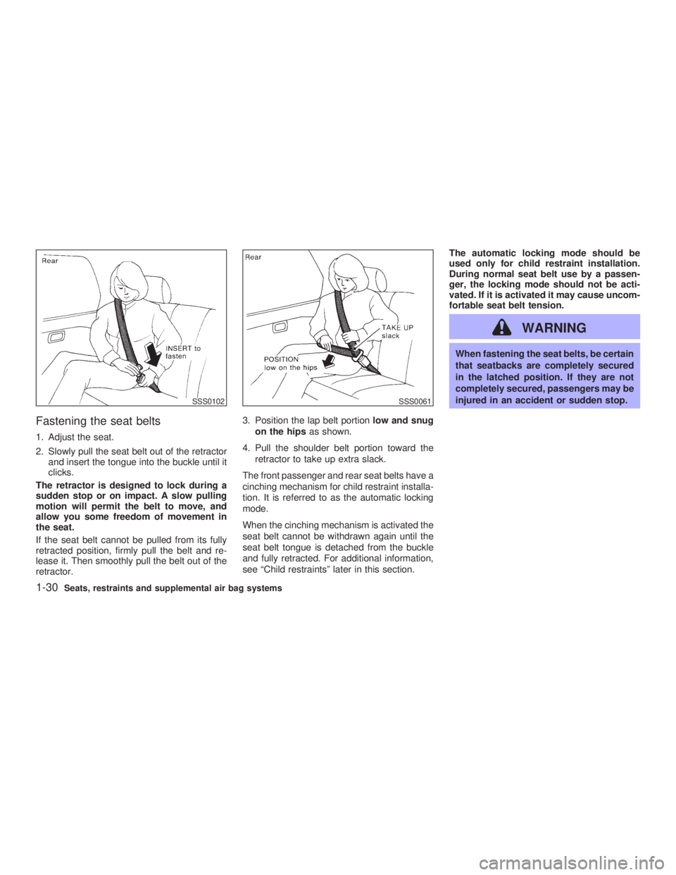
Fastening the seat belts 1. Adjust the seat.
2. Slowly pull the seat belt out of the retractor
and insert the tongue into the buckle until it
clicks.
The retractor is designed to lock during a
sudden stop or on impact. A slow pulling
motion will permit the belt to move, and
allow you some freedom of movement in
the seat.
If the seat belt cannot be pulled from its fully
retracted position, firmly pull the belt and re-
lease it. Then smoothly pull the belt out of the
retractor. 3. Position the lap belt portion low and snug
on the hips as shown.
4. Pull the shoulder belt portion toward the
retractor to take up extra slack.
The front passenger and rear seat belts have a
cinching mechanism for child restraint installa-
tion. It is referred to as the automatic locking
mode.
When the cinching mechanism is activated the
seat belt cannot be withdrawn again until the
seat belt tongue is detached from the buckle
and fully retracted. For additional information,
see ªChild restraintsº later in this section. The automatic locking mode should be
used only for child restraint installation.
During normal seat belt use by a passen-
ger, the locking mode should not be acti-
vated. If it is activated it may cause uncom-
fortable seat belt tension.
WARNING When fastening the seat belts, be certain
that seatbacks are completely secured
in the latched position. If they are not
completely secured, passengers may be
injured in an accident or sudden stop.SSS0102 SSS0061
1-30 Seats, restraints and supplemental air bag systems
Z 02.11.1/V35-D/V5.0
X
Page 54 of 256

2 Instruments and controls Instrument panel ....................................................... 2-2
Meters and gauges ................................................... 2-3
Speedometer and odometer ................................ 2-4
Tachometer .......................................................... 2-4
Engine coolant temperature gauge ...................... 2-5
Fuel gauge ........................................................... 2-5
Compass display ...................................................... 2-6
Warning/indicator lights and audible reminders ........ 2-9
Checking bulbs ..................................................... 2-9
Warning lights....................................................... 2-9
Indicator lights .................................................... 2-11
Audible reminders .............................................. 2-13
Security systems ..................................................... 2-13
Vehicle security system ...................................... 2-13
Infiniti Vehicle Immobilizer System ................... 2-14
Windshield wiper and washer switch ...................... 2-16
Rear window and outside mirror (if so equipped)
defroster switch ....................................................... 2-16
Headlight and turn signal switch ............................. 2-17
Xenon headlights (if so equipped) ..................... 2-17
Headlight switch ................................................. 2-17
Turn signal switch .............................................. 2-19
Fog light switch ....................................................... 2-20
Hazard warning flasher switch ................................ 2-20 Horn......................................................................... 2-21
Heated seats (if so equipped) ................................. 2-21
Vehicle dynamics control (VDC) off switch ............ 2-22
Clock ....................................................................... 2-23
Adjusting the time............................................... 2-23
Power outlet ............................................................ 2-23
Cigarette lighter and ashtray (accessory) ............... 2-24
Storage .................................................................... 2-25
Instrument pocket (Except for Navigation system
equipped models) ............................................... 2-25
Pocket (Manual transmission model) ................. 2-25
Glasses case ...................................................... 2-26
Cup holder .......................................................... 2-26
Glove box ........................................................... 2-27
Upper glove box (Except for Navigation system
equipped models) ............................................... 2-28
Console box ....................................................... 2-28
Rear armrest pocket ........................................... 2-29
Cargo net............................................................ 2-29
Coat hook (Coupe) ............................................. 2-30
Stowing golf bags ............................................... 2-30
Windows .................................................................. 2-31
Power windows .................................................. 2-31
Automatic adjusting function (Coupe) ................ 2-33
Z 02.7.29/V35-D/V5.0
X
Page 64 of 256

Parking brake indicator:
When the ignition key is in the ON position, the
light comes on when the parking brake is
applied.
Low brake fluid warning light:
The light warns of a low brake fluid level. If the
light comes on while the engine is running with
the parking brake not applied, stop the vehicle
and perform the following:
1. Check the brake fluid level. Add brake fluid
as necessary. See ªBrake fluidº in the ª8.
Do-it-yourselfº section.
WARNINGO Your brake system may not be work-
ing properly if the warning light is on.
Driving could be dangerous. If you
judge it to be safe, drive carefully to
the nearest service station for re-
pairs. Otherwise, have your vehicle
towed because driving it could be
dangerous.
O Pressing the brake pedal with the
engine stopped and/or low brake fluid level may increase your stopping dis-
tance and braking will require greater
pedal effort as well as greater pedal
travel.
O If the brake fluid level is below the
MIN mark on the brake fluid reservoir,
do not drive until the brake system
has been checked at an INFINITI re-
tailer.
2. If the brake fluid level is correct, have the
warning system checked by an INFINITI
retailer.
ABS component warning light:
The electronic component of ABS does not
work properly, if the light comes on together
with the anti-lock brake warning light when the
brake fluid is correct and the parking brake is
released. Have the system checked by an
INFINITI retailer. Drive vehicle at speeds and
avoid abrupt braking.
Charge warning light If the light comes on while the engine is
running, it may indicate that the charging sys-
tem is not functioning properly. Turn the en-
gine off and check the alternator belt. If the belt is loose, broken, missing or if the light remains
on, see your INFINITI retailer immediately.
CAUTION Do not continue driving if the belt is
loose, broken or missing.
Door open warning light This light comes on when any of the doors are
not closed securely while the ignition key is
ON.
Engine oil pressure warning
light This light warns of low engine oil pressure. If
the light flickers or comes on during normal
driving, pull off the road in a safe area, stop the
engine immediately and call an INFINITI re-
tailer or other authorized repair shop.
The engine oil pressure warning light is not
designed to indicate a low oil level. Use the
dipstick to check the oil level. See ªEngine
oilº in the ª8. Do-it-yourselfº section.
2-10 Instruments and controls
Z 02.7.29/V35-D/V5.0
X
Page 66 of 256

on, the cruise control system is operational.
Cruise set switch indicator
lightThe light comes on while the vehicle speed is
controlled by the cruise control system. If the
light blinks while the engine is running, it may
indicate the cruise control system is not func-
tioning properly. Have the system checked by
your INFINITI retailer.
High beam indicator light
(Blue)This light comes on when the headlight high
beam is on and goes out when the low beam is
selected.
Malfunction indicator lamp
(MIL)If the malfunction indicator lamp comes on
steady or blinks while the engine is running, it
may indicate a potential emission control mal-
function.
The malfunction indicator lamp may also come
on steady if the fuel filler cap is loose or
missing, or if the vehicle runs out of fuel.
Check to make sure the fuel filler cap is
installed and closed tightly, and that the ve- hicle has at least three gallons (14 liters) of fuel
in the fuel tank.
After a few driving trips, the lamp should
turn off if no other potential emission control
system malfunction exists.
Operation
The malfunction indicator lamp will come on in
one of two ways:
O Malfunction indicator lamp on steady Ð An
emission control system malfunction has
been detected. Check the fuel filler cap. If
the fuel filler cap is loose or missing, tighten
or install the cap and continue to drive the
vehicle. The lamp should turn off after
a few driving trips. If the lamp does
not turn off after a few driving trips, have the
vehicle inspected by an authorized
INFINITI retailer. You do not need to have
your vehicle towed to the retailer.
O Malfunction indicator lamp blinking Ð An
engine misfire has been detected which
may damage the emission control system.
To reduce or avoid emission control system
damage:
a) Do not drive at speeds above 45 MPH
(72 km/h).
b) Avoid hard acceleration or deceleration.
c) Avoid steep uphill grades. d) If possible, reduce the amount of cargo
being hauled or towed.
The malfunction indicator lamp may stop
blinking and come on steady.
Have the vehicle inspected by an autho-
rized INFINITI retailer. You do not need to
have your vehicle towed to the retailer.
CAUTION Continued vehicle operation without
having the emission control system
checked and repaired as necessary
could lead to poor driveability, reduced
fuel economy, and possible damage to
the emission control system.
Slip indicator light This indicator will blink when the VDC system
or the traction control system is operating, thus
alerting the driver to the fact that the road
surface is slippery and the vehicle is nearing
its traction limits.
Vehicle dynamics control off
indicator light The light comes on when the vehicle dynamics
2-12 Instruments and controls
Z 02.7.29/V35-D/V5.0
X
Page 70 of 256

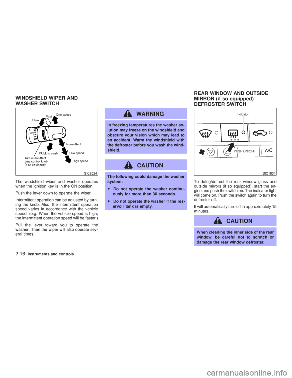
The windshield wiper and washer operates
when the ignition key is in the ON position.
Push the lever down to operate the wiper.
Intermittent operation can be adjusted by turn-
ing the knob. Also, the intermittent operation
speed varies in accordance with the vehicle
speed. (e.g. When the vehicle speed is high,
the intermittent operation speed will be faster.)
Pull the lever toward you to operate the
washer. Then the wiper will also operate sev-
eral times. WARNING In freezing temperatures the washer so-
lution may freeze on the windshield and
obscure your vision which may lead to
an accident. Warm the windshield with
the defroster before you wash the wind-
shield.
CAUTION The following could damage the washer
system:
O Do not operate the washer continu-
ously for more than 30 seconds.
O Do not operate the washer if the res-
ervoir tank is empty. To defog/defrost the rear window glass and
outside mirrors (if so equipped), start the en-
gine and push the switch on. The indicator light
will come on. Push the switch again to turn the
defroster off.
It will automatically turn off in approximately 15
minutes.
CAUTION When cleaning the inner side of the rear
window, be careful not to scratch or
damage the rear window defroster.SIC2024 SIC1831
WINDSHIELD WIPER AND
WASHER SWITCH REAR WINDOW AND OUTSIDE
MIRROR (if so equipped)
DEFROSTER SWITCH
2-16 Instruments and controls
Z 02.7.29/V35-D/V5.0
X
Page 73 of 256

Instrument brightness control The instrument brightness control operates
when the light switch is in the or
position.
Turn the control to adjust the brightness of
instrument panel lights and clock (except
power window switch lights).
When the control is turned upward until it
stops, the light intensity will be at maximum.
When the control is turned downward until it
stops, the light will be turned off. Headlight beam select To select the high beam, push the lever for-
ward. Pull it back to select the low beam.
Flashing signal Pulling the lever toward you will flash the
headlight high beam.
Daytime running light system
(Canada only) The headlights automatically illuminate at a
reduced intensity when the engine is started
with the parking brake released. The daytime
running lights operate with the headlight switch
in the OFF position or in the position.
Turn the headlight switch to the position
for full illumination when driving at night.
If the parking brake is applied before the
engine is started, the daytime running lights do
not illuminate. The daytime running lights illu-
minate once the parking brake is released.
The daytime running lights will remain on until
the ignition switch is turned off. WARNING When the daytime running light system
is active, tail lights on your vehicle are
not on. It is necessary at dusk to turn on
your headlights. Failure to do so could
cause an accident injuring yourself and
others.
TURN SIGNAL SWITCH
Turn signal Move the lever up or down to signal the turning
direction. When the turn is completed, the turn
signals cancel automatically.
Lane change signal To indicate a lane change, move the lever up
or down to the point where lights begin flash-
ing.SIC0922
Instruments and controls
2-19
Z 02.7.29/V35-D/V5.0
X
Page 84 of 256

Small cargo net (Sedan for Canada) COAT HOOK (Coupe)
CAUTION Avoid hanging heavy goods on the
hook.
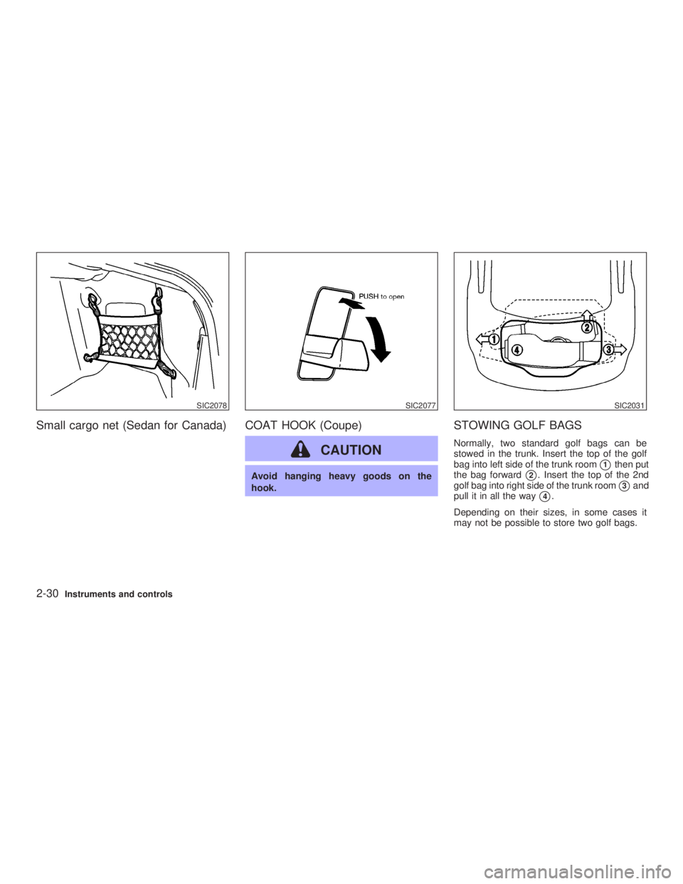
STOWING GOLF BAGS Normally, two standard golf bags can be
stowed in the trunk. Insert the top of the golf
bag into left side of the trunk room
j 1
then put
the bag forward
j 2
. Insert the top of the 2nd
golf bag into right side of the trunk room
j 3
and
pull it in all the way
j 4
.
Depending on their sizes, in some cases it
may not be possible to store two golf bags.SIC2078 SIC2077 SIC2031
2-30 Instruments and controls
Z 02.7.29/V35-D/V5.0
X
Page 106 of 256

INTERIOR TRUNK LID RELEASE
WARNINGClosely supervise children when they
are around cars to prevent them from
playing and becoming locked in the
trunk where they could be seriously in-
jured. Keep the car locked, with the
trunk closed, when not in use, and pre-
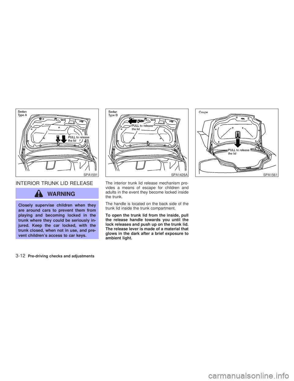
vent children's access to car keys. The interior trunk lid release mechanism pro-
vides a means of escape for children and
adults in the event they become locked inside
the trunk.
The handle is located on the back side of the
trunk lid inside the trunk compartment.
To open the trunk lid from the inside, pull
the release handle towards you until the
lock releases and push up on the trunk lid.
The release lever is made of a material that
glows in the dark after a brief exposure to
ambient light.SPA1591 SPA1426A SPA1561
3-12 Pre-driving checks and adjustments
Z 02.7.29/V35-D/V5.0
X