Page 368 of 415
�µ
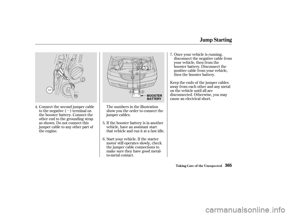
Connect the second jumper cable
to the negative ( ) terminal on
the booster battery. Connect the
other end to the grounding strap
as shown. Do not connect this
jumper cable to any other part of
the engine.Once your vehicle is running,
disconnect the negative cable f rom
your vehicle, then f rom the
booster battery. Disconnect the
positive cable f rom your vehicle,
then the booster battery.
Keep the ends of the jumper cables
away from each other and any metal
on the vehicle until all are
disconnected. Otherwise, you may
cause an electrical short.
Start your vehicle. If the starter
motor still operates slowly, check
the jumper cable connections to
make sure they have good metal-
to-metal contact. If the booster battery is in another
vehicle, have an assistant start
that vehicle and run it at a fast idle. The numbers in the illustration
show you the order to connect the
jumper cables.
4.
6.7.
5.
Jump Starting
T aking Care of t he Unexpect ed365
BOOSTER
BATTERY
Page 373 of 415
This indicator should come on when
the ignition switch is ON (II), and go
out af ter the engine starts. If it
comes on brightly when the engine
is running, it indicates that the
charging system has stopped
charging the battery.By eliminating as much of the
electrical load as possible, you can
drive several miles (kilometers)
before the battery is too discharged
to keep the engine running. Drive to
a service station or garage where
you can get technical assistance.
Immediately turn of f all electrical
accessories:radio,heater,A/C,
climate control, rear def ogger, cruise
control, etc. Try not to use other
electrically-operated controls such as
the power windows. Keep the engine
running and take extra care not to
stall it. Starting the engine will
discharge the battery rapidly.
Charging System Indicator
T aking Care of t he Unexpect ed370
CHARGING SYSTEM INDICATOR
Page 375 of 415
Your vehicle has certain ‘‘readiness
codes’’ that are part of the on-board
diagnostics f or the emissions
systems. In some states, part of the
emissions testing is to make sure
these codes are set. If they are not
set, the test cannot be completed.
If your vehicle’s battery has been
disconnected or gone dead, these
codes are erased. It takes several
days of driving under various
conditions to set the codes again.If possible, do not take your vehicle
f or a state emissions test until the
readiness codes are set. Ref er to
State Emissions Testing f or more
inf ormation. (See page .)
To check if they are set, turn the
ignition ON (II), but do not start the
engine. The Malf unction Indicator
Lamp will come on f or 20 seconds. If
it then goes of f , the readiness codes
are set. If it blinks 5 times, the
readiness codes are not set.
395
Readiness Codes
Malf unction Indicator L amp
T aking Care of t he Unexpect ed372
Page 378 of 415

CONT INUED
The secondary f use box is in the
engine compartment next to the
battery.If something electrical in your
vehicle stops working, the first thing
youshouldcheckforisablownfuse.
Determine f rom the chart on page
to , or the diagram on the
f use box lid (the diagram f or the
driver’s side interior f use box is on
the kick panel below the f use box),
which f use or f uses control that
component. Check those f uses f irst,
but check all the f uses bef ore
deciding that a blown f use is not the
cause. Replace any blown f uses and
check the component’s operation.
Turn the ignition switch to LOCK
(0). Make sure the headlights and
all other accessories are off.
Remove the cover f rom the f use
box. Check each of the large f uses in
the primary under-hood f use box
by looking through the top at the
wire inside. Removing these f uses
requires a Phillips-head screw-
driver.
1.
2. 379377
3.
Fuses
T aking Care of t he Unexpect ed
Checking and Replacing Fuses
375
FUSE
BLOWN
SECONDARY UNDER-HOOD FUSE BOX
Page 380 of 415

�µ�Î
�Î
�Î
CONT INUED
Amps.
No. Circuits Protected No. Amps. Circuits Protected
If the replacement fuse of the
same rating blows in a short time,
there is probably a serious
electrical problem in your vehicle.
Leave the blown fuse in that
circuit and have your vehicle
checked by a qualif ied mechanic.
If the driver’s power window f use is
removed, the AUTO feature of the
driver’s window will be disabled. You
should reset the AUTO f eature (see
page ).
If the radio f use is removed, the
audio system will disable itself . The
nexttimeyouturnontheradioyou
will see ‘‘ ’’ in the f requency
display. Use the Preset buttons to
enter the f ive-digit code (see page ).
6.
126
200
20 A
30 A
15 A
15 A
15 A
20 A
15 A
20 A
1
2
3
4
5
6
7
8
9 Spare Fuse
Spare Fuse
Right Headlight
ACG S
Hazard
Not Used
Stop
Lef t Headlight
ABS F/S 10
11
12
13
14
15
16
17
18
19
20
21
22
23
24
40 A
30 A
30 A
40 A
40 A
40 A
30 A
7.5 A 10 A
15 A
120 A 30 A
7.5 A 50 A
30 A Power Window Motor
Power Sliding Door
Rear Defroster
Back Up, ACC
Power Seat
Heater Motor
Cooling Fan
Spare Fuse
Spare Fuse
Spare Fuse
Battery
Condenser Fan
MG Clutch
Ignition Switch (IG 1 Main)
ABS Motor
: EX and EX-L models
On EX and EX-L models
Fuses
T aking Care of t he Unexpect ed377
PRIMARY UNDER-HOOD FUSE BOX
Page 384 of 415
If you decide to tow your vehicle
with all f our wheels on the ground,
make sure you use a properly-
designed and attached tow bar.
Prepare the vehicle for towing as
described above, and leave the
ignition switch in Accessory (I) so
the steering wheel does not lock.
Make sure the radio and any items
plugged into the accessory power
socket are turned of f so they do not
rundownthebattery.
Emergency T owing
T aking Care of t he Unexpect ed381
The steering system can be damaged if
the steering wheel is locked. Leave the
ignition switch in Accessory (I), and
make sure the steering wheel turns
f reely bef ore you begin towing.Trying to lif t or tow your vehicle by the
bumpers will cause serious damage.
The bumpers are not designed to
support the vehicle’s weight.
Page 390 of 415
")
�µ
�µ
�µ
�µ
�µ
�µ
�µ
�µ
�µ
�µ
�µ
�µ
�µ
�µ
�µ
Specif ications
T echnical Inf ormation387
Lights
Battery
Fuses Engine
Alignment
Tires
12 V 21 W
12 V 21/5 W
3.50 x 3.66 in (89.0 x 93.0 mm)
212 cu-in (3,471 cm
)
10 : 1
0.00 in (0.0 mm)
0.00 in (0.0 mm) 0°
0°30’
2°07’
225/60R16 98T
T135/80D16 101M
36 psi (250 kPa , 2.5 kgf/cm
)
60 psi (420 kPa , 4.2 kgf/cm)
24/2.2 CP
12 V 1.8 W 12 V 8 W 12 V 21 W
12 V 3 CP 2CP
21 CP (18 W)
4CP
10 W
12 V
12 V
12 V
12 V 12 V
60/55 W (HB2)
12 V
65 AH/20 HR 52 AH/5 HR
12 V
12 V
Headlights
Front turn signal/parking/side
marker lights
Rear turn signal lights
Stop/Taillights/Rear side
marker lights
Taillights
Back-up lights
License plate light
High-mount brake light
Individual map lights
Cargo area light
Vanity mirror lights
Capacity
Interior
Under-hood Type
BorexStroke
Displacement
Compression ratio
Spark plugs
Toe-in
Camber
Caster
Size
Pressure
See page 379or the fuse label
attached to the dashboard.
See page 379or the fuse label
attached to the inside of the fuse
box door under the dashboard. See spark plug maintenance sec-
tion page 316 .
See pages 377and 378or the fuse
box cover.
High/Low
Front/Rear
Spare
Front/Rear
Spare Front
Rear
Front
Rear
Front
Front
Rear
Driver’s side
Passenger’s side (Amber)
Water cooled 4-stroke SOHC VTEC,
6-cylinder, gasoline engine
Page 398 of 415

CONT INUED
If you take your vehicle f or a state
emissions test shortly af ter the
battery has been disconnected or
gone dead, it may not pass the test.
This is because of certain ‘‘readiness
codes’’ that must be set in the on-
board diagnostics f or the emissions
systems. These codes are erased
when the battery is disconnected,
and set again only after several days
of driving under a variety of
conditions.If the testing f acility determines that
the readiness codes are not set, you
will be requested to return at a later
date to complete the test. If you must
get the vehicle re-tested within the
next two or three days, you can
condition the vehicle for re-testing
by doing the f ollowing.
Make sure the gas tank is nearly,
but not completely, f ull (around
3/4).
Make sure the vehicle has been
parked with the engine of f f or 8
hours or more.
Make sure the ambient
temperature is between 20° and
95°F. Without touching the accelerator
pedal, start the engine and let it
idle f or 20 seconds.
Keep the vehicle in Park
(automatic transmission). Increase
the engine speed to 2,000 rpm and
hold it there until the temperature
gauge rises to at least 1/4 of the
scale (approximately 3 minutes).
T echnical Inf ormation
St at e Emissions T est ing
T esting of Readiness Codes
395
, and go
out af ter the engine starts. If it
comes on brightly when the engine
is running, it indicates that the
charging system has st")

