Page 538 of 1139

EPS Indicator Circuit Troubleshooting
1.Turn the ignition switch ON (ll), start the engine,
and watch the EPS indicator.
Does the EPS indicator come on?
YES lf the EPS indicator comes on and goes off, it's
OK. lf the EPS indicator stays on or blinks. go to
step 12.
NO Go to step 2.
Turn the ignition switch OFF, then ON (ll) again,
and watch the brake system indicator,
Does the brake system indicator come on?
YES-Go to step 3.
NO Repair open in the indicator power source
circuit.l. Blown No. 10 (7.5A)fuse.
. Open in the wire between the No. 10 (7.5A) fuse
and gauge assembly.. Open circuit inside the under-dash fuse/relay box,. Faulty gauge assembly.
Turn the ignition switch OFF,
Connect a jumper wire between the gauge
assembly 22P connector terminal No. 13 and body
ground, then turn the ignition switch ON (ll).
GAUGE ASSEMBLY 22P CONNECTOR (Blue connector)
Wire side of female terminals
Does the EPS indicator come on?
YES-Go to step 5.
NO Inspect the EPS indicator bulb, if the bulb is
OK, replace the bulb circuit board in the gauge
assembly.l
3.
4.
5. Turn the ignition switch OFF.
6. Disconnect EPS control u n it connector C (20P).
7. Turn the ignition switch ON (ll).
8. Connect EPS control unit connector C (20P)
terminal No. 6 to body ground with a jumper wire.
Wire s d€ oflemale16rmina s
Does the EPS indicatot come on?
YES Go to step 9.
NO Repair open in the wire between the gauge
assembly and the EPS control unit.l
Turn the ignition switch OFF.
Disconnect EPS control unit connector A (2P),
Check for continuity between EPS control unit
connector A terminal No. 2 and body ground.
EPS CONTROL UNITCONNECTOA A I2PI
wire s de oftemale terminals
ls there continuity?
YES Check for loose or poor connections at the
EPS control unit. lf the connections are good,
substitute a known-good EPS control unit. lf the
symptom/indication goes away, replace the
original EPS control unit and recheck.I
NO Repair open in the wire or a bad ground at
G151,t(cont'd)
9.
10.
'l 1.
EPS CONTBOL UNIT CONNECTOB C {2OP)
17-47
Page 539 of 1139

EPS Components
I
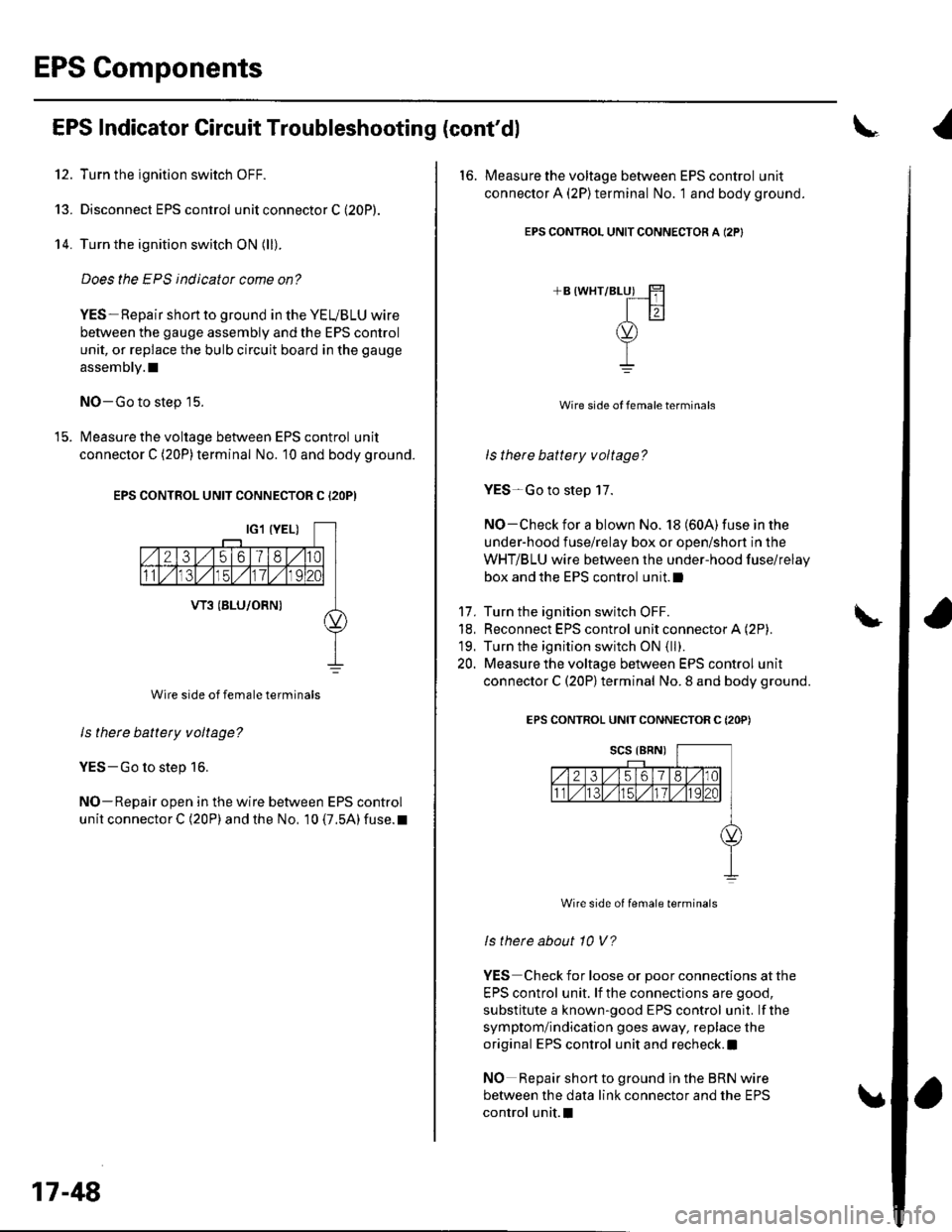
12.
EPS Indicator Circuit Troubleshooting (cont'dl
Turn the ignition switch OFF.
Disconnect EPS control unit connector C (20P).
Turn the ignition switch ON (ll).
Does the EPS indicator come on?
YES-Repair short to ground in the YEUBLU wire
between the gauge assembly and the EPS control
unit, or replace the bulb circuit board in the gauge
assembly.l
NO-Go to step 15.
Measure the voltage between EPS control unit
connector C (20P)terminal No. 10 and body ground.
EPS CONTROL UNIT CONNECTOR C I2OP)
Wire side of female terminals
ls there battery voltage?
YES-Go to step 16.
NO-Repair open in the wire between EPS control
unit connector C (20P) and the No, 10 (7.5A) fuse. t
13.
14.
17-48
16. Measure the voltage between EPS control unit
connector A (2P)terminal No. '1 and body ground.
EPS CONTROL UNITCONNECTON A (2P}
+B (WHT/BLUI H
Itr
v-L
17.
18,
19.
20.
Wire side of female terminals
ls there battery voltage?
YES-Go to step 17.
NO-Check for a blown No. 18 (604) fuse in the
under-hood fuse/relay box or open/short in the
WHT/BLU wire between the under-hood fuse/relay
box and the EPS control unit.l
Turn the ignition switch OFF.
Reconnect EPS control unit connector A (2P).
Turn the ignition switch ON (ll).
Measure the voltage between EPS control unit
connector C (20P)terminal No. 8 and body ground.
EPS CONTROL UNIT CONNECTOR C (2OP)
Wire side of female terminals
ls therc about 10 V?
YES Check for loose or poor connections at the
EPS control unit. lf the connections are good,
substitute a known-good EPS control unit. lf the
symptom/indication goes away, replace the
original EPS control unit and recheck.l
NO Repair short to ground in the BRN wire
between the data link connector and the EPS
control unit.I
Page 541 of 1139

EPS Components
(Motor RemovaUlnstallation (cont'dl
lnsiallation
7. Clean the mating surface of the motor (A) and
gearbox.
Apply a thin coat of silicone grease (P/N 08733-
8070E)to the new O-ring (B), and carefully fit it on
the motor.
Apply grease {Nippon Grease WR-S or equivalent
steering gear grease) into the motor shaft (C).
qE
8 x '1.25 mm20 N.m12.0 kgt.m,7 .2lbl ftl
L==-c].E@
9.
17-50
r0.Install the motor on the gearbox by engaging the
motor shaft and worm shaft (D). Note the motor
installation position {direction of motor wires).
Before tightening the bolts, turn the motor two or
three times right and left about 45 degrees. lvlake
sure the motor is evenly seated on the steering
gearbox and that the O-ring is not pinched betlveen
the mating surfaces.
Installthe removed Darts in the reverse order of
removal. and note these items:
lvlake sure the motor 2P connector is properly
connected.
lvlake sure the motor and EPS wires are not
caught or pinched by any parts.
Reconnect the negative cable to the battery.
Do the engine control module (ECM) idle learn
procedure (see page 11-139).
Enter the anti-theft code for the radio station
Dresets. Reset the clock,
Do the oower window control unit reset
procedure (see page 22-1241.
After installation, start the engine, and let it idle.
Turn the steering wheel from lock-to-lock several
times. Check that the EPS indicator does not come
on.
11.
12.
13.
Page 558 of 1139

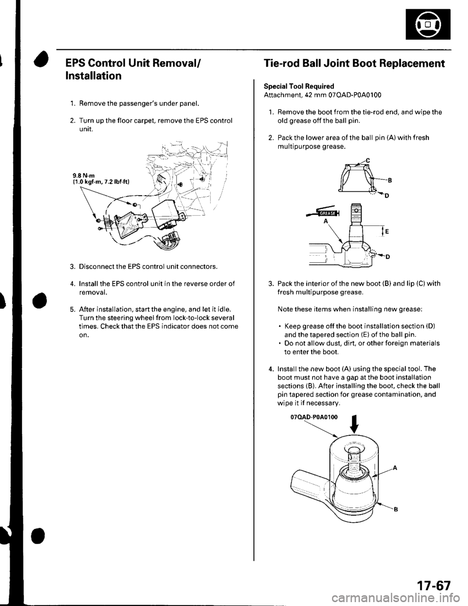
EPS Control Unit Removal/
Installation
1. Remove the passenger's under panel.
2. Turn up the floor carpel, remove lhe EPS control
untr.
Disconnect the EPS control unit connectors.
lnstallthe EPS control unit in the reverse order of
removal.
After installation, start the engine, and let it idle.
Turn the steering wheelfrom lock-to-lock several
times. Check that the EPS indicator does not come
on.
3.
E
Tie-rod Ball Joint Boot Replacement
Special Tool Required
Attachment, 42 mm 07OAD-P0A0100
l. Remove the boot from the tie-rod end, and wipe the
old grease off the ball pin.
2. Pack the lower area of the ball pin(A)wilhfresh
mulr purpose grease.
3. Pack the interior of the new boot (B) and lip (C) with
fresh multipurpose grease.
Note these items when installing new grease;
. Keep grease offthe boot installation section (D)
and the tapered section (E) of the ball pin.
. Do not allow dust, dirt, or other foreign materials
to enter the boot.
4. Installthe new boot (A) using the specialtool. The
boot must not have a gap at the boot installation
sections (B). After installing the boot. check the ball
pin tapered section for grease contamination, and
wipe it if necessary.
07(lAD-P0A0100
*-4
r/ \-,d______i.l+_D
-6rA
17-67
Page 596 of 1139

Brakes
Conventional Brake Components
Special Tools ... ..... ... l9-2
Component Location Index ......................................... 19-3
Brake System Inspection and
Tests ............... .......... 19-4
Brake Pedal and Brake Pedal Position Switch
Adjustment .............. 19-6
Parking Brake Check and
Adjustment .............. 19-7
Brake System Bleeding ...................... 19-8
Brake System Indicator Circuit
Diagram ................... 19-9
Parking Brake Switch Test ................. 19-10
Brake Fluid Level Switch Test ...................................... 19-10
Front Brake Pads lnsoection and
Replacement ........... 19-11
Front Brake Disc Inspection ............... 19-13
Front Brake Calioer Overhaul ...................................... 19-14
Master Cylinder Replacement ........... 19-15
Master Cylinder Inspection ................ 19-16
Brake Booster
Pushrod Clearance Adjustment ................................ 19-16
Brake BoosterTest ................... .......... 19-18
Brake Booster Reolacement .............. 19-19
Rear Brake Pads Inspection and
Reolacement ........... 19-20
Rear Brake Disc Inspection ................ 19-22
Rear Brake Caliper Overhaul ....................................... 19-23
Brake Hoses and Lines Insoection .... 19-24
Brake Hose Reolacement ................... 19-25
Parking Brake Cable Replacement .............................. 19-26
ABS (Anti-lock Brake System)
Gomponents ... 19-29
Page 598 of 1139

Component Location Index
FRONT BRAKESFront Brake Pads, Inspection andReplacement, page 19-1 1Front Brake DiscInspection, page 19'13Front Brake CaliperOverhaul, page 19-14
INDICATORBrake System Indicator CircuitDiagram, page 19-9Parking Brake SwitchTest, page 19 10Brake Fluid Level SwitchTest, page 19-10
BRAKE CABLE
BRAKE BOOSTERBrake BoosterTest, page 19-18Brake EoosterReplacement, page 19 19
Parking Brake CableReplacement, page 19 26
REAR DISC BRAKERear Brake Pads Inspection andReplacement, page l9-20Rear Brake DiscInspection, page 19'22Rear Brake Caliper Overhaul,page 19'23
PARKING BRAKE LEVERParkino BrakeCheck and Adjustment, page 19-7
BRAKE PEDALBrake Pedal and Erake Pedal Position SwitchAdjustment, page l9-6
BRAKE HOSES and LINESBrake Hoses and LinesInspection, page 19 24Brake HosesReplacement, page 19 25
MASTER CYLINDERMaster CylinderFl6^1.^6m6nr ^2^o 1O-18Master Cylinder Inspection, page 19-16Brake Booster Pushrod ClearanceAdjustment, page'19-16Brake System Bleeding, page 19-8
19-3
Page 604 of 1139
GRN/ORN
,tk ,o"","o ""o*.(b, 3s1E8,.""",,"
I oPEN,Leve,down
I-=:
I
A
YBtK
+csor
Brake System Indicator Circuit Diagram
UNDER.OASHFUSE/FELAYBOX
EBAK€FLUIDIEVELSwlICH
19-9
Page 607 of 1139

Conventional Brake Gomponents
Front Brake Pads Inspection and Replacement (cont'dl
3. Remove the pad retainers (A), and check the caliperpins for free movement.
/:-."
t-... .,.';-iri.: '1=' r
.. a.-
4. Clean the caliper thoroughly; remove any rust, andcheck for grooves and cracks.
5. Checkthe brake disc for damage and cracks.
6. Apply Dow Corning Molykote M77 grease to theretainers on their mating surfaces against thecaliper bracket.
7. Installthe pad retainers. Wipe excess grease offtheretainers. Contaminated brake discs and pads
reduce stopping ability. Keep grease off the discsand pads.
8. Apply Molykote l\477 grease to both sides of thepad shim {A), the back ofthe pads (B), and the other
areas indicated by the arrows.
Wipe excess grease off the shim. Contaminated
brake discs and pads reduce stopping ability. Keepgrease off the discs and pads.
Installthe brake pads and pad shim correctly.Install the pads with the wear indicators (C) on theinside.
lf you are reusing the pads, always reinstall thebrake pads in their original positions to prevent amomentary loss of braking efficiency.
, a .).
19-12
10. Push in the piston (A) so the caliper will fitoverthepads. Check the brake fluid level. The brake fluid
may overflow if the reservoir is too full. lvlake surethe piston boot is in position to prevent damaging itwhen pivoting the caliper down
8x1.0mm34 N.m3.5 kgt m.25 tbf.ft)
11. Pivot the caliper down into position. Being carefulnot to damage the pin boots, install the bolt (B), and
tighten it to the specified torque.
12. Press the brake pedal several timestomakesure
the brake works, then test drive.
NOTE: Engagement of the brake may require agreater pedal stroke immediately after the brakepads have been replaced as a set. Several
applications of lhe brake pedal will restore thenormal pedal stroke.
13. After installation, check for leaks at hose and linejoants or connections, and retighten if necessary.
\