2003 HONDA CIVIC Indicator
[x] Cancel search: IndicatorPage 514 of 1139
![HONDA CIVIC 2003 7.G Workshop Manual Symptom Troubleshooting Index
SymptomDiagnostic procedureAlso check fo]
EPS indicator does not
come on
EPS lndicator Circuit Troubleshooting (see page 17-47)
EPS indicator does not go
off and no DTC i HONDA CIVIC 2003 7.G Workshop Manual Symptom Troubleshooting Index
SymptomDiagnostic procedureAlso check fo]
EPS indicator does not
come on
EPS lndicator Circuit Troubleshooting (see page 17-47)
EPS indicator does not go
off and no DTC i](/manual-img/13/5744/w960_5744-513.png)
Symptom Troubleshooting Index
SymptomDiagnostic procedureAlso check fo]
EPS indicator does not
come on
EPS lndicator Circuit Troubleshooting (see page 17-47)
EPS indicator does not go
off and no DTC is stored
EPS Indicator Circuit Troubleshooting (see page 17-47)
EPS indicator does not stay
on, no DTC is stored, and
there is no power assist
1. Check the motor wires between the EPS control unit and the
motor for a short to ground. Repair as needed.
2. lf the motor wires are OK, replace the steering gearbox
{short in the motor).
17-23
Page 516 of 1139

EPS Gontrol Unit Inputs and Outputs at Connestor C (20P1
EPS CONTROL UNIT CONNECTOR C (2OP)
Wire side of female terminals
TerminalnumbelWire colorTerminal sign{Terminel name}DescriplionMeasuremeniTerminalsConditions{lqnition switch ON {lll)Voltage
2PNKT/S GND(Torque sensor qround)Ground for the torque
ORNvccl(Voltaqe common 1Power source fortorque3-Groundtartthe enqrneBa$erv voltaqeOV
5YEUBEDVT6(Voltaqe torque 6)Detects torque sensorstonal5 GroundStartthe engine andturn the steerino wheelAbout
YEUBLU(Warninq lamp)Drives the EPS indicatorlidhr6 GroundEPS ONtnotcatol uTl-OVBanerv voltaqe
7BLUAVHTVSP(Vehicle speed pulseiDetects the vehicle speedinput signal for the speedsensor or the ECM (4 pulse/
Raise the vehicle off theground and spin theAlternatingvoltage aboutOV 5V OV-5V
BRNSCS{Servjco check siqnal)Detects service check8-GroundSCS not groundedBattery voltage
10YELIG1llqnition 1Power source for activating10-Groundon switch ON (ll)Batterv voltaqeon switch OFF11G RN//ELvcc2(Voltaqe common 2)Drives the torque sensor1'l-Groundtan the enoineAbout5Von switch OFF8LU/ORNVT3(Voltaoe toroue 3)Detects torque sensor13-GroundStartthe engine andtrrrn the steerino wheelAbout5-0 v
YEUBLKT/SIG(Torque sensor F/SDetects torque sensorsrgnal15-GroundStartthe engineMomentarily 5 V
1'lLT GRN/BI KPSWiPower steerino switch)Provides power steeringswitch sionall7-GroundStartthe engine andnrrn the steerino wheel0-12V
19BLUNEPDetects the engine pulse19-GroundStartthe engine, and let;t idte
20GRYDIAG-HCommunications withHonda PGNI Tester20-GroundPGM Tester not5V
17-25
Page 520 of 1139

'I 1.Substitute a known-good EPS control unit, and
connect the all disconnected connectors.
Sta rt the engine.
Does the EPS indicator come on?
YES Go to step 13.
NO Check for loose EPS control unitconnectors. lf
necessary, replace the EPS control unit and
retest.l
Stop the engine, and verify the DTC.
ls DTCl2 indicated?
YES Check for loose torque sensor connectors.
lf necessary, substitute a known-good steering
gearbox and recheck.l
NO-Perform the appropriate troubleshooting for
the code indicated. !
12.
13.
DTC 16: Torque Sensor VT3 and W6
1. Clear the DTC.
2. Start the engine.
3. Wait at least 10 seconds.
Does the EPS indicator come on?
YES Go to step 4.
NO Check for loose wires or poor connnections. lf
the connections are good, the system is OK at this
time.l
4. Stop the engine, and verify the DTC.
ls DTC16 indicated?
YES-Go to step 5.
NO Perform the appropriate troubleshooting for
the code indicated. t
5. Make sure the ignition switch is OFF, then
disconnect EPS control unit connector C (20P) and
the torque sensor 6P connector.
6, Check for continuity between the appropriate EPS
control unit connector C (20P) terminal and body
ground (see table).
Terminal nameEPS control unit connector C
terminal No.
Vccl3
Vcc211
VT313
VT65
T/S GND2
W re s d€ oltemalelermi.als
ls there continuity?
YES- Repair short to body ground in the
appropriate sensor circuit between the torque
sensor and EPS control unit, !
NO Go to step 7.
{cont'd)
EPS CONINOT UNITCONNECIOR C (2OP)
17-29
Page 522 of 1139

11.
't2.
Substitute a known-good EPS control unit, and
reconnect the disconnected connectors.
Sta rt the engine.
Does the EPS indicator come on?
YES Go to step 13.
NO Check for loose or poor connections at the
EPS control unit and the torque sensor conneclors.
lf the connections are good, replace the EPS control
unit and recheck.I
Stop the engine, and verify the DTC.
ls DTC16 indicated?
YES Replace the steering gearbox and recheck.l
NO Perform the appropriate troubleshooting for
the code indicated.l
13.
DTC 17: Torque Sensor Vccl
DTC 18: Torque Sensor Vcc2
1. Clear the DTC.
2. Start the engine.
3. Wait at least 10 seconds.
4.
Does the EPS indicator come on?
YES Go to step 4.
NO Check for loose wires or poor connections. lf
the connections are good, the system is OK at this
time.I
Stop the engine, and verify the DTC.
Is DTCl7 or DTCl8 indicated?
YES Go to step 5.
NO Do the troubleshooting for the DTc
indicated.I
Make sure the ignition switch is OFF, then
disconnect EPS control unit connector C (20P) and
the torque sensor 6P connector.
Check for continuity between EPS control unit
connector C (20P)terminal No. 3 and body ground.
EPS CONTROL UNIT CONNECTOR C (2OP)
Wire side o{ female terminals
ls there continuity?
YES Repair shon to body ground in the wire
between the torque sensor and EPS control unit.I
NO Go to step 7.
(cont'd)
17-31
Page 523 of 1139

EPS Components
DTC Troubleshooting (cont'dl
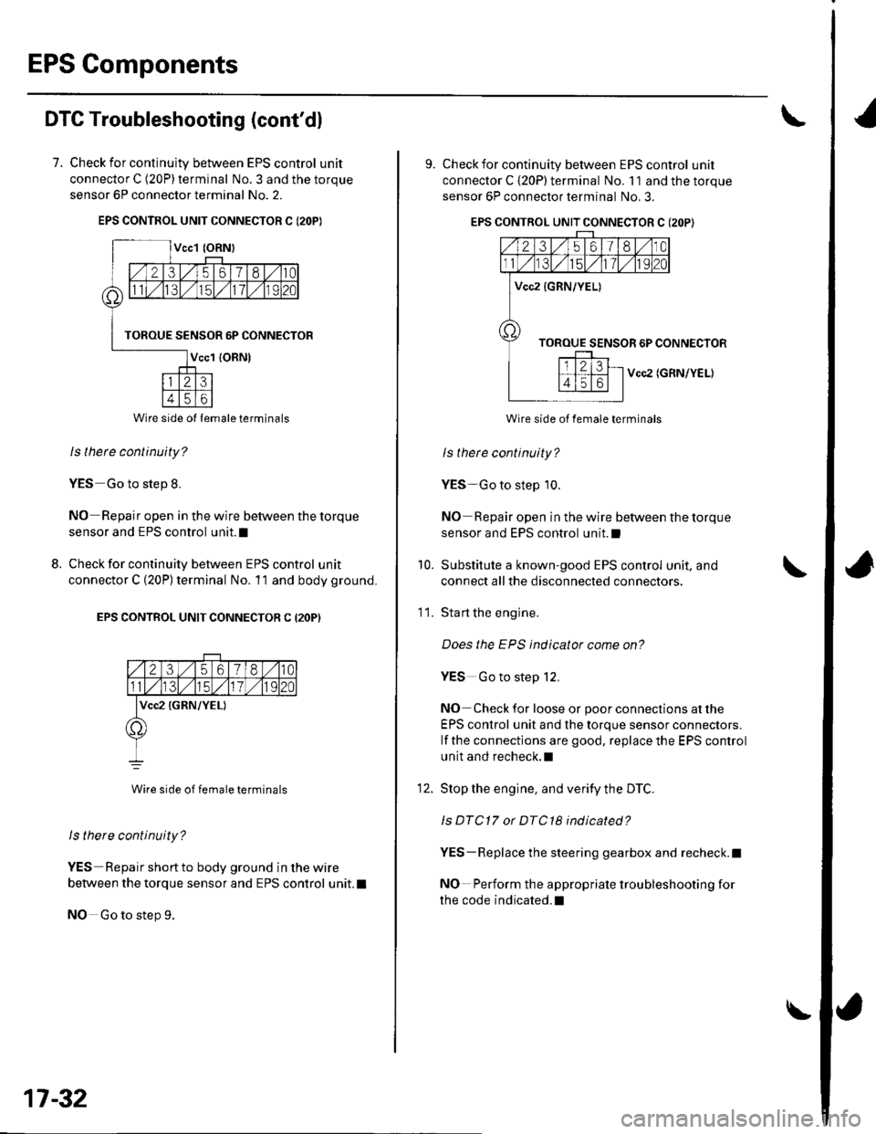
7. Check for continulty between EPS control unit
connector C (20P) terminal No. 3 and the torque
sensor 6P connector terminal No. 2.
EPS CONTROL UNIT CONNECTOR C I2OP)
ls thete continuity?
YES Go to step 8.
NO Repair open in the wire between the torque
sensor and EPS control unit.I
Check for continuity between EPS control unit
connector C (20P) terminal No. 11 and body ground.
EPS CONTROL UNIT CONNECTOR C (2OP)
2356180
lvcc2 {GRN/YEL)
Wire side of female terminals
ls there continuity?
YES Repair short to body ground in the wire
between the torque sensor and EPS control unit. t
NO Go to step 9.
8.
Wire side ol lemale terminals
17-32
\
9. Check for continuity between EPS control unit
connector C {20P) terminal No. 11 and the torque
sensor 6P connector terminal No. 3.
EPS CONTROL UNIT CONNECTOR C (2OP}
Vcc2 (GRN/YEL)
Wire side of female terminals
ls therc continuity?
YES-Go to step 10.
NO Repair open in the wire between the torque
sensor and EPS control unit.l
Substitute a known-good EPS control unit, and
connect all the disconnected connectors.
Sta rt the engine.
Does the EPS indicator come on?
YES Go to step 12.
NO Check for loose or poor connections at the
EPS control unit and the torque sensor connectors.
lf the connections are good, replace the EPS control
unit and recheck.l
Stop the engine, and verity the DTC.
ls DTC17 or DTC18 indicated?
YES-Replace the steering gearbox and recheck.l
NO Perform the appropriate troubleshooting for
the code indicated.l
10.
11.
12.
Page 524 of 1139

DTC 22: Vehicle Speed Sensor Signal
DTC 23: Engine Speed Signal
NOTE:. lf the MIL indicator is ON, troubleshoot the PGIVI-Fl
system first.. Even though the system is operating normally, the
EPS indicator will come on under the following
conditions.
- Condition 1:. The vehicle was traveling at least '12.4 mph(20 km/h), then. A rapld change in vehicle speed was detected,
then. The vehicle (or the vehicle speed sensor signal)
stopped for at least 5 seconds, and. The engine speed was still 1,640 rpm or higher for
at least 5 seconds- Condition 2:
After the vehicle (or the vehicle speed sensor
signal) has stopped for at least 10 seconds, yetthe
engine speed was still 1,640 rpm or higher for at
least 20 seconds.- Condition 3:
When the vehicle speed is 10 km/h (6.2 mph) or
above and the engine is running at 280 rpm or
below for 3 seconds.
1. Start the engine and check the tachometer.
ls the tachometer working correctly?
YES- Go to step 2.
NO-Go to step 9.
2. Test-drive the vehicle above 15 km/h {9.3 mph).
ls the speedometer working correctly?
YES Go to step 3.
NO-Perform the speedometer system
troubleshooting {see page 22-651.a
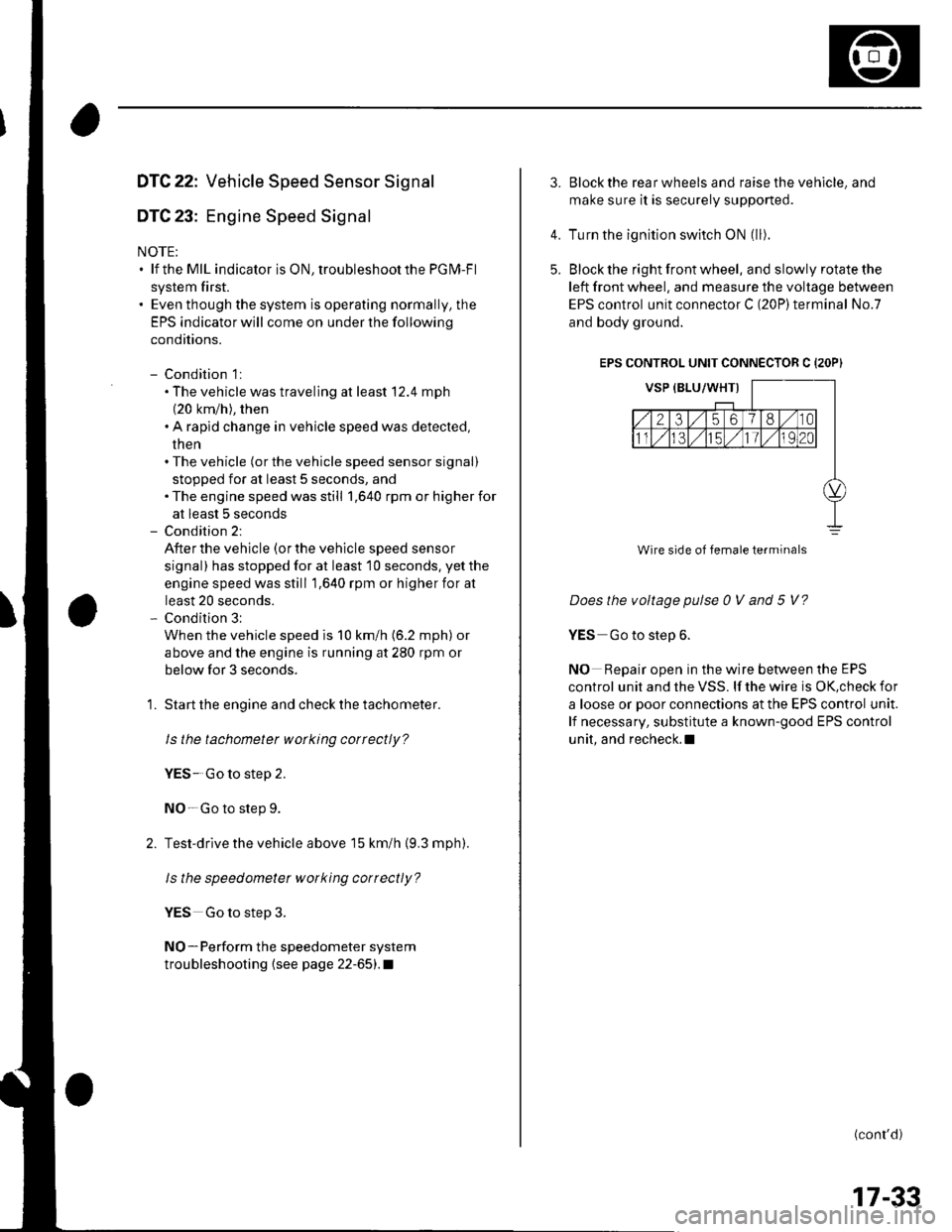
3.Block the rear wheels and raise the vehicle, and
make sure it is securely supported.
Turn the ignition switch ON (ll).
Block the right front wheel, and slowly rotate the
left front wheel, and measure the voltage between
EPS control unit connector C (20P)terminal No.7
and body ground.
EPS CONTROL UNIT CONNECTOR C {2OP)
Does the voltage pulse 0 V and 5 V?
YES Go to step 6.
NO Repair open in the wire between the EPS
control unit and the VSS. lf the wire is OK,check for
a loose or poor connections at the EPS control unit.
lf necessary, substitute a known-good EPS control
unit, and recheck.l
(conr'd)
4.
5.
Wire side of female terminals
17-33
Page 526 of 1139

'14. Check for continultv between EPS control unit
connector C (20P)terminal No. 19 and ECM
connector E (31P) terminal No. 26.
ECM CONNECTOR E {31PI
ls thete continuity?
YES-Go to step 15.
NO-Repair open in the wire between the EPS
control unit and ECM.I
Disconnect the gauge assembly 22P connector.
Check for continuity between EPS control unit
connector C (20P)terminal No. 19 and body ground,
EPS CONTROL UNIT CONNECTOR C (2OP}
Wire side of female terminals
ls there continuity?
YES Repair shortto body ground in the wire
between the EPS control unit, the test tachometer
connector, the gauge assembly, and the ECM.I
NO Check for loose ECM control unit connectors.
lf necessary, substitute a known-good ECM control
unit and recheck.I
15.
DTC 37: EPS Control Unit Internal Circuit(lnput Circuit For Motor Voltage)
1. Clear the DTC.
2. Start the engine.
3. Turn the steering wheel from lock-to-lock several
times, and wait 10 seconds or more.
Does the EPS indicator come on?
YES Go to step 4.
NO Check for loose wires or poor connections. lf
the connections are good, the system is OK at this
trme.l
4. Stop the engine, and verify the DTC.
ls DTC 37 indicated?
Y€S Check for loose EPS control unit conneclors.
lf necessary, substitute a known-good EPS control
unit and recheck.l
NO Perform the appropriate troubleshooting for
the code indicated.l
17-35
Page 527 of 1139

EPS Components
DTC Troubleshooting (cont'dl
DTC 41: Voltage For Motor
1. Clear the DTC.
2. Start the engine.
3. Turn the steering wheel from lock-to-lock several
times, and wait 10 seconds or more,
Does the EPS indicator come on?
YES-Go to step 4.
NO Check for loose wires or poor connections. lf
the connections are good, the system is OK at this
time.l
4. Stop the engine, and verify the DTC.
ls DTC 41 indicated?
YES Go to step 5.
NO Perform the appropriate troubleshooting for
the code indicated.l
5. Make sure the ignition switch is OFF, then
disconnect EPS control unit connector B (2P) and
the motor 2P conneclor.
6. Check for continuity between EPS control unit
connector B (2P) terminal No. 1 and body ground.
EPS CONTROL UNIT CONNECTOR B {2P}
M1 (RED} HF---t||
Itr(f))
T,L
Wire side of female terminals
ls there continuity?
YES Repair short to body ground in the RED wire
between the EPS control unit and the motor. !
NO-Go to step 7.
17-36
7. Check for continuity between EPS control unit
connector B (2P)terminal No. 2 and body ground.
EPS CONTROL UNIT CONNECTOR B I2P)
TitM2 {GRN) FJ
-r
o)
TI
Wire side of female terminals
ls there continuity?
YES-Repair short to body ground in the GRN wire
between the EPS control unit and the motor,l
NO Go to step 8.
Check for continuity between EPS control unit
connector B (2P)terminal No. 1 and No. 2.
EPS CONTROL UNIT CONNECTOR B {2P)
Wire side of female terminals
ls there continuity?
YES Repair short between the RED and GRN
wires in the motor circuit between the EPS control
unit and the motor.l
NO Go to step 9.
M2 (GRNI
.l
\