Page 76 of 1139

CavityWireTest conditionTest: Desired resultPossible cause il result is not obtained
6GRYiREDSet button pushedCheck for voltage to ground:
There should be battery
voltage,
When testing terminal No.6,
there should be no voltage on
terminal No. 7.
Blown No.7 (15 A)fuse in the
under-hood fuse/relay box
Faulty horn relay
Faulty sevresume/cancel
swrtch
Faulty cable reel
An open in the wire
Shon to ground (horn sounds
when button is pressed)
7LT GRN/
BLK
Resume button
pusneo
Check for voltage to ground:
There should be battery
voltage.
When testing terminal No.7,
there should be no voltage on
terminal No. 6.
BRNConnect battery
power to the BRN
terminal and ground
to the BRNIVEL
termrnal
Check the operation of the
actuator motor: You should
be able to hear the motor.
. Faulty actuator. An open in the wire11BRNI/EL
10B LUIVE Llgnition switch ON
0r)
Attach to groundi
Cruise indicator light in the
gauge assembly should come
on.
Blown No. 10 (7.5 A) fuse in
the under-dash fuse/relay box
Blown cruise indicator bulfl
Faulty gauge assembly
An open in the wire
12BLU/VVHTlgnition switch ON
(ll) and main switch
ON; raise the front of
the vehicle, and
rotate one wheel
slowly while holding
the other wheel
Check for voltage between
thE BLU/VVHT (+) ANd BLK
( )terminals:
Thereshouldbe0 5Vor
more repeatedly.
Faulty VSS
An open in the wire
Short to ground
13LT GRNlgnition switch oN
{ll) and main switch
ON
Check for voltage to ground:
There should be battery
voltage.
Blown No. 4 (10 A)fuse in the
under-dash fuse/relay box
Faulty main switch
An oDen in the wire
14LT BLUClutch pedal
reteaseo
Check for continuity to
grouno:
There should be continuity.
NOTE:There should be no
continuity when the clutch
oedal is Dressed.
Faulty clutch pedal position
swtlcn
Poor ground (G501)
Incorrect clutch switch
adjustment
An open in the wire
lf any test indicates a problem, find and correct the cause, then recheck the system. lf all the input tests prove OK,
the cruise control unit may be faulty. Substitute a known-good cruise control unit and retest. lf the system works
properly, replace the cruise control unit.
4-41
Page 124 of 1139
Gamshaft Inspection
NOTE: Do not rotate the camshaft during inspection.
1. Remove the rocker arm assembly (see page 6-26).
and disassemble it (see page 6-27).
2. Put the rocker shaft holders, camshaft, and
camshaft holders on the cylinder head, then tighten
the bolts to the specified torque.
Specified torque:
I mm bolis:
22 N.m {2.2 kgt m, 16lbf.ft}
6 mm bolts:
12 N.m {1.2 kgf.m,8.7 tbf.ftl
6 mm bolts: @, €0, @
I
I
3. Seat the camshaft by pushing it away from the
camshaft pulley end ofthe cylinder head.
4. Zero the dial indicator against the end of the
camshaft, then push the camshaft back and forth
and read the end play. lf the end play is beyond the
service limit, replace the camshaft head and
recheck. lf it is still beyond the service limit, replace
the cylinder.
Camshaft End Play:
Standard {New}: 0.05 0.20 mm(0.002 0.008 in.l
Service Limit: 0.4 mm (0.02 in.)
(cont'd)
6-29
Page 127 of 1139

Gylinder Head
Valve Inspection
1.Remove the valves (see page 6-31),
Measure the valve in these areas.
lntake Valve Dimensions
A Standard lNewl: 34.85 35.15 mm
B Standard {Newl:
C Standard lNew):
C Service Limit:
B Standard (New):
C Standard (New):
C Service Limit:
Exhaust Valve Dimensions
A Standard (New): 29.85-30.15 mm
{1.372 1.384 in.l
108.7 - 109.5 mm
14.280- 4.311 in.)
5.475 5.485 mm
10.2156-0.2159 in.)
5.445 mm {0.214 in.l
(1.175- 1.187 in.)
108.3 109.1 mm
(4.264- 4.295 in.l
5.450 5.460 mm(0.2146 0.2150 in.)
5.42 mm (0.213 in.)
2.
.<
6-32
t-
Valve Stem-to-Guide Clearance\
Inspection
1.Remove the valves (see page 6-3'1).
Slide the valve out of its guide about 10 mm. then
measure the guide-to-stem clearance with a dial
indicator while rocking the stem in the direction of
normal thrust (wobble method).. lf the measurement exceedsthe service limit,
recheck it using a new valve.. lf the measurement is nowwithin the service
limit, reassemble using a new valve.. lf the measurementwith a newvalve still
exceeds the service limit, go to step 3.
lntake Valve Stem-to-Guide Clearance:
Standard lNew): 0.06 0.11 mm
{0.002 0.004 in.}
Service Limil: 0.16 mm {0.006 in.)
Exhaust Valve Stem-to-Guide Clearance:
Standard lNewl:0.11 -0.16 mm
10.004 0.006 in.)
Service Limit: 0.22 mm 10.009 in.)
Subtract the O.D. of the valve stem. measured with
a micrometer, from the LD. of the valve guide,
measured with an inside micrometer or ball gauge.
Take the measurements in three places along the
valve stem and three places inside the valve guide.
The difference between the largest guide
measurement and the smallest stem measurement
should not exceed the service limit
lntake Valve Stem-to-Guide Clearance:
Standard (New): 0.030 0.055 mm
{0.0012 0.0022 in.)
Service Limit; 0.08 mm (0.003 in.l
Exhaust Valve Stem-to-Guide Clearance:
Standard {Newl: 0.055 0.080 mm(0.0022-0.003r in.l
Service Limit: 0.11 mm (0.004 in.)
(
3.
4,.
I
Page 143 of 1139

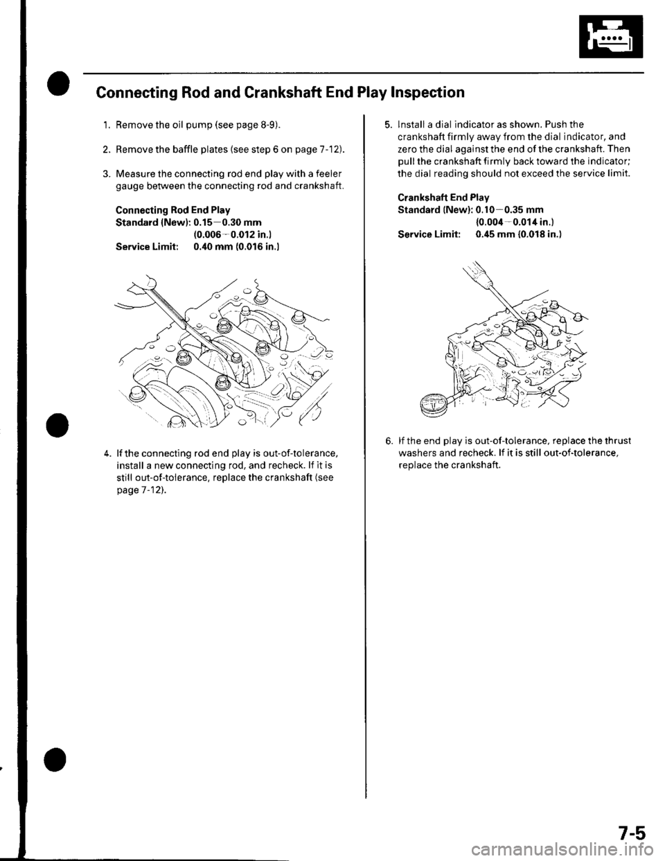
Connecting Rod and Crankshaft End Play Inspection
1.Remove the oil pump (see page 8-9).
Remove the baffle plates (see step 6 on page 1 -12).
3. Measure the connecting rod end play with a feeler
gauge between the connecting rod and crankshaft.
Connecting Rod End Play
Standard {New): 0.15 0.30 mm(0.006-0.012 in.l
Service Limit 0.40 mm (0.016 in.l
4.lf the connecting rod end play is out-of-tolerance,
install a new connecting rod, and recheck. lf it is
still out-of-tolerance, replace the crankshaft (see
page 7 -12],.
5. lnstall a dial indicator as shown. Push the
crankshaft firmly away from the dial indicator, and
zero the dial against the end of the crankshaft. Then
pull the crankshaft firmly back toward the indicator;
the dial reading should not exceed the service limit.
Crankshaft End Plav
Standard lNew): 0.10-0.35 mm
{0.004-0.014 in.l
Service Limit: 0.45 mm {0.018 in.)
lf the end play is out-of-tolerance, replace the thrust
washers and recheck. lf it is still out-of-tolerance,
replace the crankshaft.
7-5
Page 157 of 1139
v
Inspection
NOTE: Inspect the piston, piston pin, and connecting
rod when they are at room temperature.
1. Measure the diameter of the piston pin.
Piston Pin Diameter
Standard (New): 21.961 21.965 mm(0.8646-0.8648 in.)
Service Limit: 21.953 mm 10.8643 in.l
2. Zerc the dial indicator to the piston pin diameter.
3. Check the difference between the Diston Din
diameter and piston pin hole diameter in the piston.
Piston Pin-to-Piston Clearance
Standard (Newl: -0.005 to +0.002 mm(-0.00020 to +0.00008 in.)
Service Limit: 0.005 mm (0.0002 in.)
Measure the piston pin-to-connecting rod clearance.
Piston Pin.to-Connecting Rod Clearance
Standard (New): 0.005 0.015 mm
{0.0002 0.0006 in.}
Service Limil: 0.02 mm (0.0008 in.l
4.
(cont'd)
7-19
Page 170 of 1139

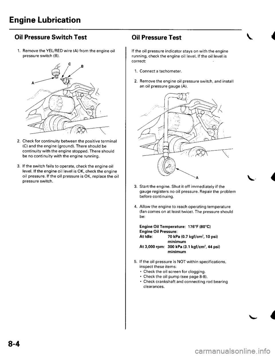
Engine Lubrication
Oil Pressure Switch Test
1. Remove the YEURED wire (A)from the engine oilpressure switch (B).
Check for continuity between the positive terminal(C) and the engine (ground). There should be
continuity with the engine stopped. There should
be no continuity with the engine running.
lf the switch fails to operate, check the engine oil
level. lf the engine oil level is OK. check the engine
oil pressure. lf the oil pressure is OK, replace lhe oil
Dressure switch.
2.
8-4
Oil Pressure Test
lf the oil pressure indicator stays on with the engine
running. check the engine oil level. lf the oil level is
correct:
Connect a tachometer.
Remove the engine oil pressure switch, and install
an oil pressure gauge {A).
{
'1.
\.(
4.
Sta rt the engine. Shut it off immediately if thegauge registers no oil pressure. Repair lhe problem
before continuing.
Allow the engine to reach operating temperature(fan comes on at least twice), The pressure should
be:
Engine Oil Temperature: 176'F (80'Cl
Engine Oil Pressure:
At ldle:70 kPa (0.7 kgf/cm', 10 psi)
mtntmum
At 3,000 rpm: 300 kPa (3.1 kgf/cm',44 psi)
minimum
lf the oil pressure is NOT within specifications,
inspect these items:. Check the oil screenforclogging.. Check the oil pump (see page 8-8).. Check crankshaft and connecting rod bearing
clearances.
I
Page 177 of 1139
1.
Balancer Shaft Inspection
Seat the balancer shaft by pushing it away from the
oil pump sprocket end ofthe oil pump.
Zero the dial indicator against the end of the
balancer shaft, then push the balancer shaft back
and forth and read the end olav.
Balancer Shaft End Play:
Fronl Balancer Shaft:
Standard {Newl: 0.070 0.135 mm
{0.0028 0.0053 in.}
Service Limit: 0.15 mm (0.006 in.)
Rear Balancer Shaft:
Standard {New): 0.070-0.135 mm(0.0028 0.0053 in.l
Service Limit: 0.15 mm (0.006 in.)
2.
3. Remove the baffle plate (A) and upper balancer
shaft holder {with bearings) (B), then remove the
front balancer shaft (C) and rear balancer shaft (D).
9H.A''/.r L=] j/
R
Rfl|]
3I] UUr Be
+-
(cont'd)
8-11
Page 210 of 1139

General Troubleshooting Information
Intermittent Failures
The term "intermittent failure" means a svstem mav
have had a failure. but it checks OK now. lf the
Malfunction Indicator Lamp (MlL) on the dash does not
come on, check for Door connections or loose terminals
at all connectors related to the circuit that Vou are
troubleshooting.
Opens and Shorts
"Ooen" and "Short" are common electrical terms. An
open is a break in a wire or at a connection. A short is
an accidental connection of a wire to ground or to
another wire. In simple electronics, this usually means
something won't work at all. With complex electronics(such as ECMs)this can sometimes mean something
works, but not the way it's supposed to.
How to Use the PGM Tester or a Scan Tool
lf the MIL {Malfunction Indicator Lamp} has come on
'1. Start the engine and check the MIL {A).
NOTE: lf the ignition switch is turned ON (ll), and
the engine is not started, the MIL will stay on for
15 20 seconds (see page 11-46).
K-> ;"PN/.- -::: - -d V-: !
w:ix&K#
2. lf the MIL stays on, connect the Honda PGM Tester(A) or an OBD ll scan tool to the Data Link
Connector {DLC) (B) located under the driver's side
of the dashboard.
3.
5.
Turn the ignition switch ON (ll).
Check the Diagnostic Trouble Code (DTC) and note
it. Also check the freeze data. Refer to the DTC
Troubleshooting Index, and begin the appropriate
troubleshooting procedure.
lf you do not find any DTCS, go to MIL circuit
troubleshooting (see page 11-97).
NOTE:. Freeze data indicates the engine conditions when the
first malfunction, misfire, or fuel trim malfunction
was detected.. The scan tool and the Honda PGM Tester can read the
DTC, freeze data, current data, and other Engine
Control l\4odule {EClvl) data.. For specific operations, refer to the user's manual
that came with the scan tool or Honda PG l\4 Tester.
lf the MIL did not stay
lf the MIL did not come on but there is a driveability
problem, refer to the Symptom Troubleshooting Index
in this section.
lf you can't duplicate the DTC
Some of the troubleshooting in this section requires
you to reset the ECM and try to duplicate the DTC. lf rhe
problem is intermittent and you can't duplicate the code,
do not continue through the procedure. To do so will
only result in confusion and, possibly, a needlessly
replaced ECM.
(cont'd)
11-3