2003 HONDA CIVIC Turn signal
[x] Cancel search: Turn signalPage 25 of 1139

t
v
2-13
o
o
a
ItemMeasurementOualilicationSpecitication
ELECTRICAL
RATINGS
Battery12V 36 AH/5 hours
Sta rter12 V-.1.1 kW, 1.2 kW
Alternator12V 95A,90A
FusesUnder-hood fuse80 A, 60 A, 50 A, 40 A, 30 A, 20 A, 15 A, 10 A, 7.5 A
Under'dash Iuse30 4,20 a, 15 A, 10 A,7.5 A
Light bulbsHeadlight high
beam
'12 v.' 60 w
Headlight low
beam
12V 55W
Frontturn signal
liqhts
12V 21W
Front parlinq lights12V 5W
Bear turn signal
lights
12V " 21W
FronVrear side
marker lights
12V 5W
Brale/taillighls12V 21/5W
High moLrnt brake
light
12V 5W
Back up lights12V 21W
License plate light12V 5W
Ceiling light'12 v'.8 w
Cargo area light12V 5W
Spotlights12V 5W
Gauge lights
Indicator lightsLED
Side turn signal
light
12V 5W
Page 219 of 1139

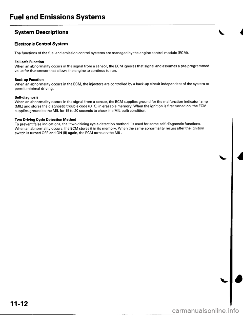
Fuel and Emissions Systems
System Descriptions
Electronic Control System
The functions of the fuel and emlssion control systems are managed by the engine control module (ECM).
Fail-safe Function
When an abnormality occurs in the signal from a sensor, the ECI\4 ignores that signal and assumes a pre-programmed
value for that sensor that allows the enqine to continue to run.
Back-up Function
When an abnormality occurs in the ECM, the injectors are controlled by a back-up circuit independent of the system to
permit minimal driving.
Self-diagnosis
When an abnormality occurs in the signal from a sensor, the ECM supplies ground for the malfunction indicator lamp
{MlL) and stores the diagnostic trouble code {DTC) in erasable memory. When the ignition is first turned on, the EClvl
supplies ground to the l\4lL for 15 to 20 seconds to check the M lL bulb condition.
Two Driving Cycle Detection Method
To prevent false indications, the "two driving cycle detection method" is used for some self-diagnostic functions.
When an abnormality occurs, the ECM stores it in its memory. When the same abnormality recurs afterthe ignition
switch is turned OFF and ON (ll) again, the ECM turns on the MlL.
\
11-12
\.
\{
Page 229 of 1139
![HONDA CIVIC 2003 7.G Workshop Manual Fuel and Emissions Systems
System Descriptions (contdl
ECM lnputs and Outputs at Connector E (31P}
L
u
1iMoFPR
2sr-{]zs3LG34SG3
6$1025HTC
1M RLY
8AFSHTCR
I
14FTP15ELD
16EPSLD
18ACC20Z/VBS21VSV
22BKSW HONDA CIVIC 2003 7.G Workshop Manual Fuel and Emissions Systems
System Descriptions (contdl
ECM lnputs and Outputs at Connector E (31P}
L
u
1iMoFPR
2sr-{]zs3LG34SG3
6$1025HTC
1M RLY
8AFSHTCR
I
14FTP15ELD
16EPSLD
18ACC20Z/VBS21VSV
22BKSW](/manual-img/13/5744/w960_5744-228.png)
Fuel and Emissions Systems
System Descriptions (cont'dl
ECM lnputs and Outputs at Connector E (31P}
L
u
1iMoFPR
2sr-{]zs3LG34SG3
6$1025HTC
1M RLY
8AFSHTCR
I
14FTP15ELD
16EPSLD
18ACC20Z/VBS21VSV
22BKSW23K-LINE24SEFMJ26NEP
21rMoCD
29scs30WEN31MIL
Wire side of female terminals
NOTE: Standard battery voltage is '12 V.
TerminalnumberWire colorferminal nameDescription Signal
GRNI/ELIMO FPR (IMMOBILIZERFLJEL PUMP RELAYIDrives PGM Fl main relay 20Vfor2 seconds after turning ignition switch ON{ll). then batterv voltaoe2WHT/REDSHO2S (SECONDARYHEATED OXYGEN SENSOR(SECONDARY HO2S),SENSOR 2r
Detects secondary HO2S{sensor 2) signalWith throttle Jully opened from idle with fullywarmed up engine: above 0.6VWith throttle quickly closed: below 0.4 V
3BRN/YELLG3 (LOGIC GROUND)cround forthe ECM/PCMcontrolcircuitLess than 1.0 V at all times
4PNKSG3 {SENSOR GBOUND)Sensor oroundLess than 1.0 V at all times5YEUELUVCC3 {SENSOR VOLTAGE)Provides sensor voltageWith ignition switch ON (ll): about 5 VWith ionition switch OFF: about 0 V6BLKATr'HTSO25HTC (SECONDARYHEATED OXYGEN SENSOR(SECONDARY H02S)HEATER CONTROL)
Drives secondary HO2SheaterWith ignition switch ON (ll): baftery voltageWilh fullv warmed up engine running: dul,controlled
1REDA/ELMRLY (PGM.FI MAINRELAY}Drives PGM-Flmain relay 1Power source forthe DTCWith ignition switch ON (ll): about 0 VWith ignition switch OFF: battery voltage
IORNAFSHTCR {AIR FUEL BATIO(Iy'F)SENSOR HEATERCONTROL RELAY)
Drives air fuel ratio sensorheater relayWith ignition swirch ON {ll): 0 V
IYEUBLKIGl (IGNITION SIGNAL)Detecrs ignition signalWith ignition switch ON (ll): battery voltageWith iqnition switch OFF: about 0 V't4LT GRNFIP lFUEL TANKPRESSURE (FTP) SENSOR)Detects FTP sensor signalWith ignition switch ON (ll) and fuel fill cap open:about 2.5 VGRN/REDELD (ELECTRICAL LOADDETECTOF)Detects ELD signalWith ignition swjtch ON itt):aOoutO.t V l-gV(deDendino on electrical load)LT GRN/8LKEPSLD (ELECIRICALPOWEB STEEBING LOADDETECT)
Detects Power steering loadsrgnalAt idle with steering wheel in straight aheadposition: about 0 VAt idle with steering wheelatfull lock: momentary
'18REDACC (Ay'C CLUTCH RELAY)Drives P,/C clutch relayWith compressor ON: about 0 VWith comoressor OFF: batterv voltaoe
11-22
\-
Page 230 of 1139

ECM Inputs and Outputs at Connector E (31P)
ltMoFPR
2$.c2s
i6SFIO2SHTC
1
IV RLY
IAFSHTCR
9tGl
14FTP15ELD
16EPSLD
t8202,4/BS21VSV
22BKSW23K LINE24SEFMJ26NEP
21lvoCD
29scs30WEN31MIL
Wire side of female terminals
NOTE: Standard battery voltage is 12 V.
TerminalWire colorTerminalnameDescriptionSignal
20BLU/RED2WBS (EVAPORATIVEEMISSION (EVAP)BYPASSSOLENOID VALVE)
Drives EVAP bypass With ignition switch ON (ll): baftery voltagesolenoid valve
21LT GRN/REDVSV (EVAPORATIVE
EI\4ISSION iEVAP)CANISTEB VENT SHUTVALVE)
Drives EVAP canister ventshut valveWith ignilion switch ON (ll): battery voltage
22WHT/BLKBKSW lBRAKE PEDALPOSITION SWITCH)Detects brake pedaloosition switch sionalWith brake pedal released: about 0 VWith hrake nedal nresse.l: batterv voltaoe23LT BLUK-LIN ESends and receives scanWith ignition switch ON (li)r pulses or battery
YELSEFMJCommunicates withmrltinleY eontrol unitWith ignition switch ON (ll): about 5 VWith enoine runnino under load: DUlses26BLUNEP (ENGINE SPEEDPULSE)Outputs engine speed pulseWith engine running: pulses
21RED/BLU \40CD fl\4MOBTLTZERCODE)Detects imrnobilizer signal
29BRNSCS (SERVICE CHECKSIGNAL)Oetects service check signalWith the service check signal shorted with the PGMTester: about 0 VWiih rhe service check sional ooened: about 5 V
30RED,A/VHTWEN (WRITE ENABLESIGNALiDetects write enable signal With ignition switch ON (ll): about 0 V
GRN/ORNMIL (MALFUNCTION
INDICATOR LAMP)Drives N4lLWith MIL turned ON: about 0 VWith MIL turned OFF: batterv voltaqe
(cont'd)
11-23
Page 234 of 1139

lgnition Timing Control
The ECM contains the memory for basic ignition timing
at various engine speeds and manifold absolute
pressure. lt also adjusts the timing according to engine
coolant temperature.
Iniector Timing and Duration
The ECM contains the memory for basic discharge
duration at various engine speeds and manifold
pressures. The basic discharge duration, after being
read out from the memory, is further modified by
signals sent from various sensors to obtain the final
discharge duration.
By monitoring long term fuel trim, the ECM detects long
term malfunctions in the fuel system and sets a
Diagnostic Trouble Code {DTC).
Intake Air Temperature (lAT) Sensor
The IAT sensor is a temperature dependent resistor
{thermistor). The resistance of the thermistor decreases
as the intake air temDerature increases.
Knock Sensor
The knock control system adjusts the ignition timing to
minimize knock.
PIEZOCERAMIC
Malfunction Indicator Lamp lMlLl Indication {ln relation
to Readiness Codes)
The vehicle has certain "readiness codes" that are part
of the on-board diagnostics for the emissions systems.
lf the vehicle's baftery has been disconnected or gone
dead. if the DTCS have been cleared, or if the ECM has
been reset. these codes are set to incomplete. In some
states, part of the emissions testing is to make sure
these codes are set to comDlete. lf all of them are not
set to complete, the vehicle may fail the test and the
test cannot be finished.
To check if the readiness codes are set to complete,
turn the ignition switch ON (ll). but do not start the
engine.TheMILwill comeonforlS 20seconds. lf it
then goes off, the readiness codes are set to complete,
lf it blinks severaltimes, one or more readiness codes
are not set to comolete. To set each code, drive the
vehicle or run the engine as described in the
procedures to set them in this section (see page 1 1-46).
Manifold Absolute Pressure {MAP) Senso]
The MAP sensor converts manifold absolute pressure
into electrical signals to the ECM.
SENSOR UNIT
(cont'd)
11-27
Page 239 of 1139

Fuel and Emissions Systems
(
{
System Descriptions (cont'd)
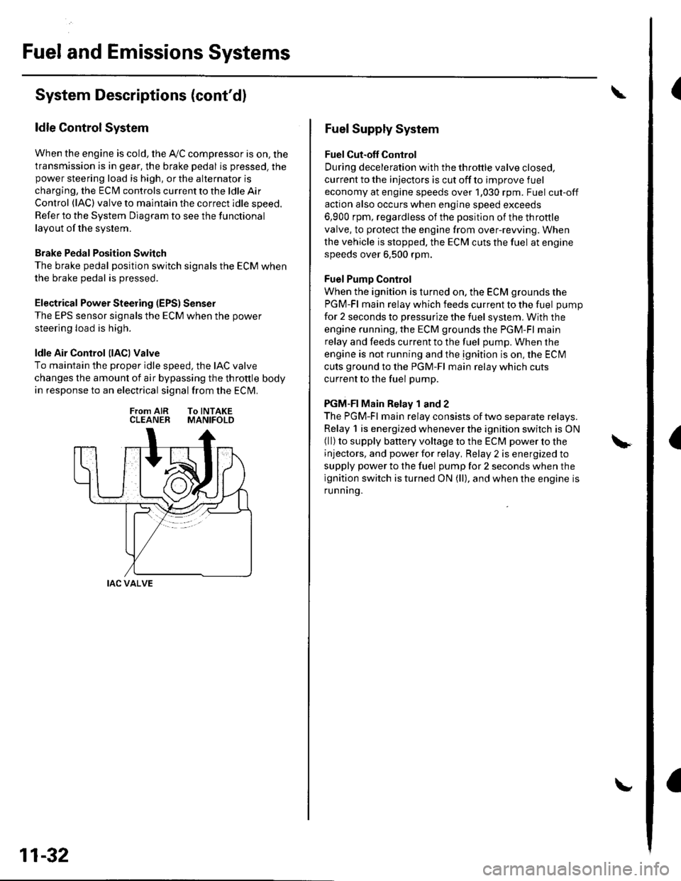
ldle Control System
When the engine is cold, the Ay'C compressor is on, the
transmission is in gear, the brake pedal is pressed. thepower steering load is high, or the alternator is
charging, the ECIM controls current to the ldle Air
Control (lAC) valve to maintain the correct idle speed.
Refer to the System Diagram to see the functional
layout of the system.
Brake Pedal Position Switch
The brake pedal position switch signals the ECM when
the brake pedal is oressed.
Electrical Power Steering (EPS) Senser
The EPS sensor signals the ECM when the power
steering load is high.
ldle Air Control llACl Valve
To maintain the proper idle speed, the IAC valve
changes the amount of air bypassing the throttle body
in response to an electrical signal from the ECM.
From AIR To INTAKECLEANER MANIFOLD
IAC VALVE
11-32
Fuel Supply System
Fuel Cut-off Control
During deceleration with the throttle valve closed,
current to the injectors is cut off to improve fuel
economy at engine speeds over 1,030 rpm. Fuel cut-off
action also occurs when engine speed exceeds
6,900 rpm, regardless of the position of the throttle
valve, to protect the engine from over-rewing. When
the vehicle is stopped. the ECM cuts the fuel at engine
speeds over 6,500 rpm.
Fuel Pump Control
When the ignition is turned on, the ECM grounds the
PGM-Fl main relay which feeds current to the fuel pump
for 2 seconds to pressurize the fuel system, With the
engine running. the ECM grounds the PGM-Fl main
relay and feeds current to the fuel pump. When the
engine is not running and the ignition is on, the ECI\4
cuts ground to the PGM-Fl main relay which cuts
current to the fuel pump.
PGM-FI Main Relay 1 and 2
The PGM-Fl main relay consists of two separate relays.
Relay 1 is energized whenever the ignition switch is ON(ll) to supply battery voltage to the ECM power to the
injectors, and power for relay, Relay 2 is energized to
supply power to the fuel pump for 2 seconds when the
ignition switch is turned ON (ll), and when the engine is
runnrng.
Page 261 of 1139

PGM-FI System
a
DTC Troubleshooting (cont'dl
DTC Pl128: MAP Sensor Signal Lower Than
Expected
1. Turn the ignition switch ON (ll).
2. Check the MAP with the scan tool.
ls 54.1 kPa(406mmHg, 16.0in.Hg), 1.6 V, or
higher indicated?
YES- Intermittent failure. system is OK at this
time.I
NO Replace the MAP sensor.l
11-54
\
\
DTC Pl129: MAP Sensor Signal Higher Than
Expected
1. Start the engine. Hold the engine at 3,000 rpm with
no load (in neutral) until the radiator fan comes on,
then Iet it idle.
2. Check the MAP with the scan toot.
ls 36.9 kPa (277 mmHg, 10.9 in.Hg), 1.1 V , or less
indicated?
YES- lntermittent failure, system is OK at this
time.l
NO Replace the MAP sensor.l
\
Page 270 of 1139

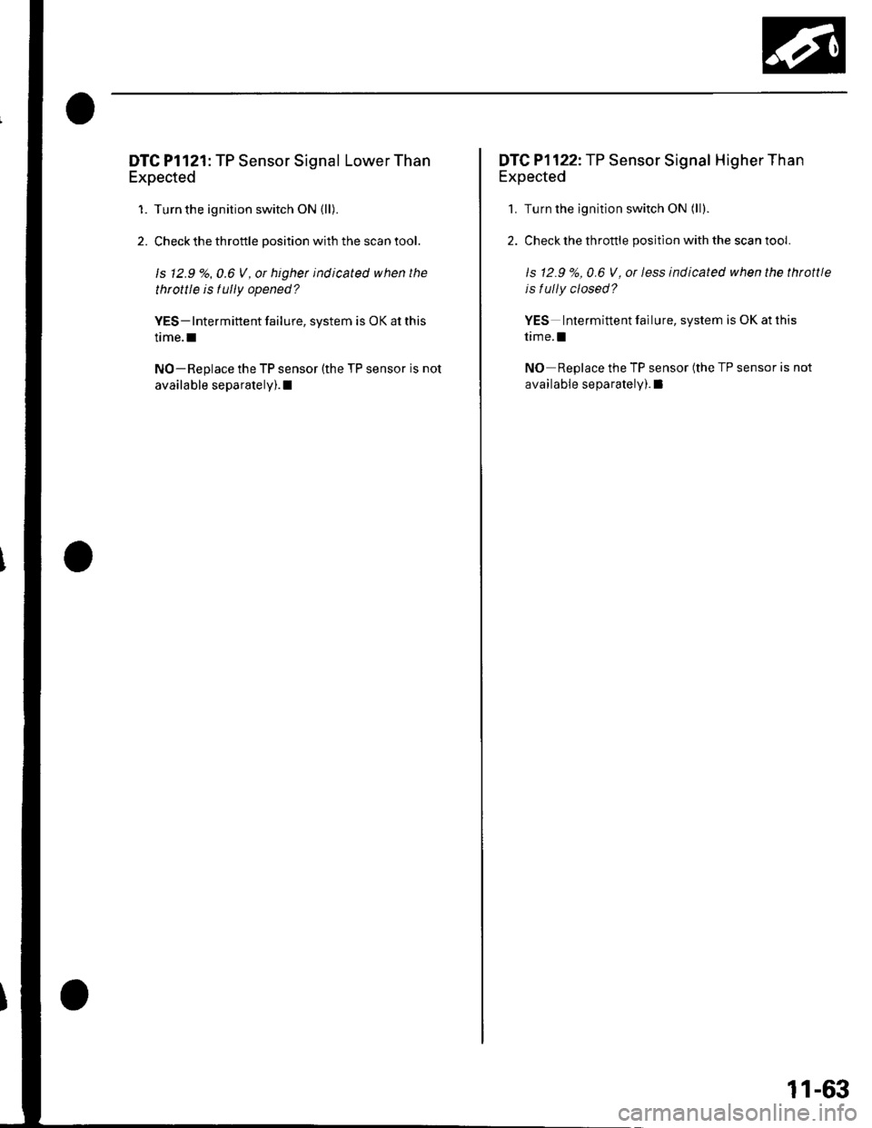
DTC Pl121: TP Sensor Signal Lower Than
Expected
1. Turn the ignition switch ON (ll).
2. Check the throttle position with the scan tool.
ls 12.9'/.,0.6 V, or higher indicated when the
throttle is tully opened?
YES- Intermittent failure, system is OK at this
time.I
NO-Replace the TP sensor (the TP sensor is not
available separately). I
DTCP1122:.fP Sensor Signal Higher Than
Expected
1. Turn the ignition switch ON (ll).
2. Check the throttle position with the scan tool.
ls 12.9 %,0.6 V, or less indicated when the throttle
is f ully closed?
YES Intermittent failure, system is OK at this
time.l
NO Replace the TP sensor (the TP sensor is not
available separately). I
11-63