2003 HONDA CIVIC weight
[x] Cancel search: weightPage 10 of 1139

General Information
Lift and Support Points
NOTE: If you are going to remove heavy componentssuch as suspension or the fuel tank from the rear of thevehicle, first supportthe front ofthe vehicle with tallsafety stands. When substantialweight is removed
from the rear of the vehicle, the center of gravity canchange and cause the vehicle to tip forward on the hoist.
Frame Hoist
1. Position the hoist lift blocks (A), or safety stands,under the vehicle's front support points (B) and rearsupport points (C).
2. Raise the hoist a few inches, and rock the vehiclegently to be sure it is firmly supported.
3. Raise the hoistto full height, and inspectthe liftpoints for solid contact with the lift blocks.
Safety Stands
To support the vehicle on safety stands. use the samesuppon points (B and C) as for a frame hoist, Alwaysuse satety stands when working on or under anyvehicle that is supported only by a jack.
1-8
Floor Jack
1. Set the parking brake.
2. Block the wheels that are not being lifted.
3. When lifting the rear of the vehicle. put thegearshift Iever in reverse.
4. Position the floor jack under the front jacking
bracket (A) or rear jacking bracket (B), center thejacking bracket in the jack lift ptatform (C), and jack
up the vehicle high enough to fit the safety standsunder it.
c
Position the safety stands underthe support points
and adjust them so the vehicle will tevet.
Lower the vehicle onto the stands.
0
Jt
Page 11 of 1139

Towing
lf the vehicle needs to be towed, call a professional
towing service. Never tow the vehicle behind another
vehicle with just a rope or chain. lt is very dangerous.
Emergency Towing
There are three popular methods of towing a vehicle.
Flat-bed Equipment The operator loads the vehicle
on the back of a truck. This is the best way of
transporting the vehicle.
To accommodate flat-bed equipment. the vehicle is
equipped with towing hooks (A)and tie down hooks {B).
The towing hook can be used with a winch to pull the
vehicle onto the truck, and the tie down hooks slots can
be used to secure the vehicle to truck.
1-9
Wheel Lift Equipment The tow truck uses two
pivoting arms that go under the tires (front or rear) and
lifts them off the ground. The other two wheels remain
on the ground. This is an acceptable way of towing the
vehicle.
Sling-type Equipment The tow truck uses metal
cables with hooks on the ends. These hooks go around
parts of the frame or suspension and the cables lift that
end of the vehicle off the ground. The vehicle's
suspension and body can be seriously damaged if this
method of towing is attemPted.
lf the vehicle cannot be transported by flat-bed, it
should be towed with the front wheels off the ground lf
due to damage, the vehicle must be towed with the
front wheels on the ground, do the following:
. Release the parking brake.. shift the transmission in Neutral.
It is best to tow the vehicle no farther than 50 miles (80
km), and keep the speed below 35 mph (55 km/h).
. lmproper towing preparation will damage the
transmission. Follow the above procedure exactly. lf
you cannot shift the transmission, the vehicle must
be transDorted on a flat-bed.. Trying to lift or tow the vehicle by the bumpers will
cause serious damage, The bumpers are not
designed to support the vehicle's weight.
Page 23 of 1139

L
v
2-11
Design Specifications
O
o
o
|temMeasurementOualificationSpecilication
DIMENSIONSOveralllength4,210 mm {165.8 in.)
Overallwidth1,695 mm 166.7 in.)
Overallheight1,440 mm (56.7 in.)
2,570 mm (101.2 in.)
Trackrront1,470 mm (57.9 in.)
Rear'1,470 mm (57.9 in.i
Ground clearance152 mm (5.98 in.)
Seating capacityfour {4)
wEtGt-iT {u.s.A.)Gross Vehicle Weight Rating
(GVWR)
3,660 rbs
WEIGHT
(CANADA)
Gross Vehicle Weight Rating
{GVWR)
1,660 kg
ENGIN ETvpeWater cooled. 4 stroke DOHC V-EC engin(
Cylinder arrangementInline 4'cylinder, transverse
Bore and stroke86 x 86 mm (3.39 x 3.39 in.)
Displacement1,998 cm'(122 cu in.)
Compression ratio9.8
Valve trainChain drive. DOHC VTEC 4 valves per cylinder
Lubrication systemForced, wet sump, with trochoid pumP
Oil pump displacementAt 6,000 engine
rpm
54.3 0 (57.4 US qo/minute
Water pump displacementAt 3,400 engine82 0 (87 US qt)/minute
F!el requiredUNLEADED gasoline with 86 pump octane number or higher
STARTERTvpeGear reduction
Normaloutput
Nominalvoltage12V
Hour rating30 seconds
Direction of rotationClockwise as viewecl from gear end
CLUTCHClutch tvpeSinqle plate dry, diaphragm spring
Clutch friction material surface area174 cm'{26.97 sq in.)
I\,1AN UAL
TRANSMISSION
TvpeSvnchronized, s-speed forward, 1 reverse
Primarv reductionDirect 1:1
Gear ratiolst3.062
2nd1.769
3rd1.212
4th0.921
5th0.738
Reverse3.583
FinalreductionTypeSinole helicalgear
Gear ratio4.164
Page 577 of 1139

Lower Arm Removal/lnstallation
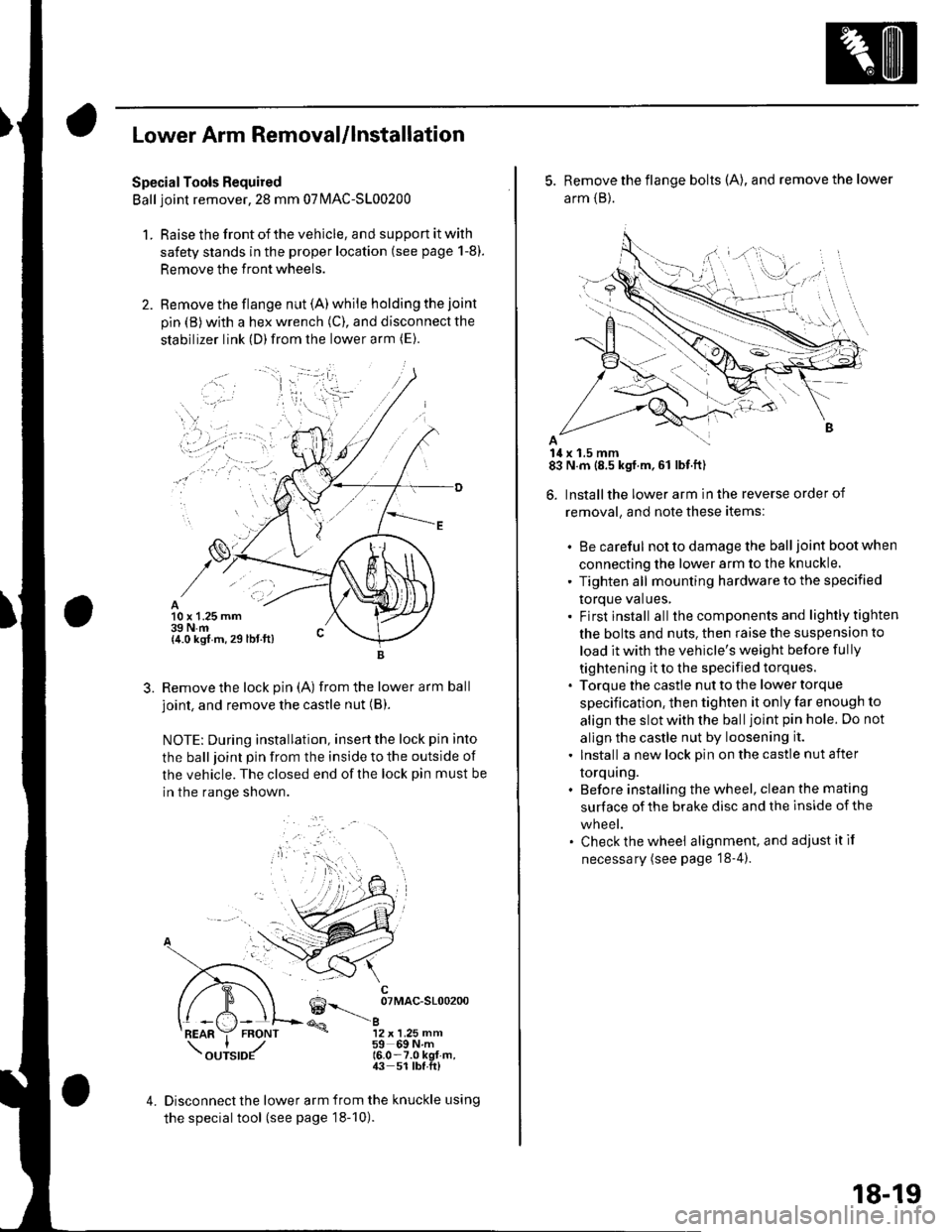
SpecialTools Required
Ball joint remover,2S mm 07|MAC-S100200
1. Raise the front of the vehicle, and support it with
safety stands in the proper location (see page 1-8).
Remove the front wheels.
Remove the flange nut (A) while holding the joint
pin {B) with a hex wrench (C), and disconnect the
stabilizer link (D)from the lower arm (E).
10 x 1.25 mm39 N.m{4.0 kgf m, 29 lbt.ft)
3.Remove the lock pin (A) from the lower arm ball
joint, and remove the castle nut (B).
NOTE: During installation, insertthe lock pin into
the ball joint pin from the inside to the outside of
the vehicle. The closed end of the lock pin must be
in the range shown.
6--__ oTMAc-sloo2oo
@a12 x 1.25 mm59 69Nm16.0-7.0 kgt-m,43 51 lbf.ft)
4.Disconnect the lower arm from the knuckle using
the special tool (see page 18-10).
5. Remove the flange bolts (A), and remove the lower
arm {B}.
14 x 1.5 mm83 N.m (8.5 kgf.m,61 lbf.ft)
6. Installthe lower arm in the reverse order of
removal, and note these items:
. Be careful not to damage the ball joint boot when
connecting the lower arm to the knuckle.
' Tighten all mounting hardware to the specified
torque values,. Firstinstall all the components and lightlytighten
the bolts and nuts. then raise the suspension to
load it with the vehicle's weight before fully
tightening it to the specified torques.. Torque the castle nut to the lower torque
specification, then tighten it only far enough to
align the slot with the ball joint pin hole. Do not
allgn the castle nut by loosening it.
. Install a new lock pin on the castle nut after
torquing.. Before installing the wheel, clean the mating
surface of the brake disc and the inside of the
wneet.. Check the wheel alignment, and adjustitif
necessary (see page '18-4).
18-19
Page 583 of 1139

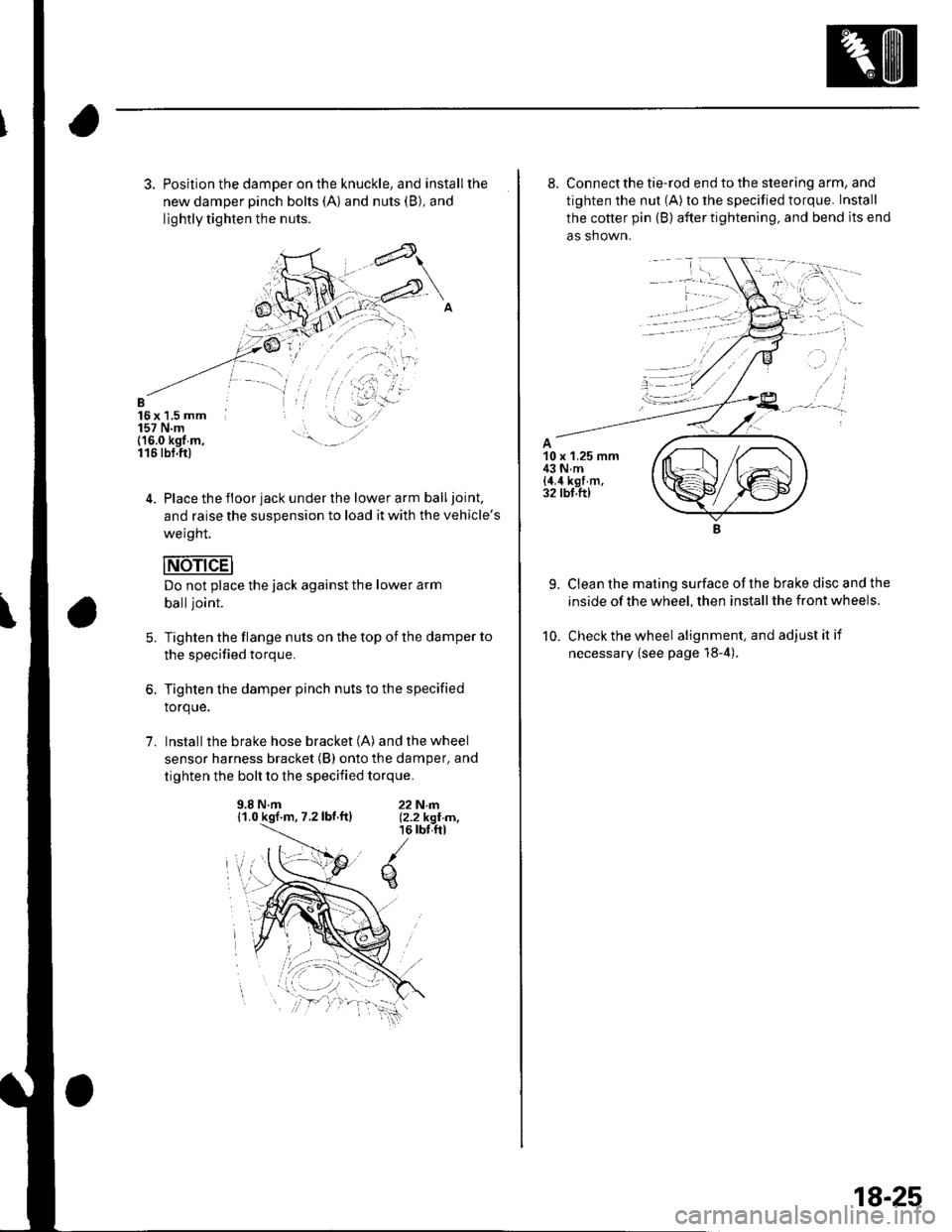
3. Position the damper on the knuckle, and installthe
new damper pinch bolts (A) and nuts (B), and
lightly tighten the nuts.
B16x 1,5 mm157 N.m(16.0 kgt m,116 tbt.ftl
4. Place the floor jack under the lower arm balljoint,
and raise the suspension to load it with the vehicle's
weight.
Do not place the jack against the lower arm
balljoint.
Tighten the flange nuts on the top of the damper to
the specified torque.
Tighten the damper pinch nuts to the specified
torque.
Install the brake hose bracket (A) and the wheel
sensor harness bracket (B) onto the damper, and
tighten the bolt to the specified torque.
5.
1.
9.8 N.m11.0 kgf.m, 7.2lbf.ftl22N|rl.12.2 kgI m,16 rbr,ftl
q
8. Connect the tie-rod end to the steering arm, and
tighten the nut (A) to the specified torque. Install
the cotter pin (B) after tightening, and bend lts end
as shown.
9. Clean the mating surface ofthe brake disc and the
inside of the wheel, then install the front wheels.
10. Check the wheel alignment, and adjustitif
necessary {see page 18-4).
18-25
Page 587 of 1139

5. Place the floor jack under the trailing arm {A), to
support it.
Do not place the jack against the plate
section of the lower arm, Be careful not to
damage any suspension components.
12 x 1.25 mm59 N.m{6.0 ksf.m.43lbf.ft)
1.
Remove the flange bolt (B), and disconnect the
upper arm {C) from the knuckle.
Mark the cam positions of the adjusting bolt (A) and
adjusting cam (B), the remove the self-locking nut
{C}, adjusting cam, and adjusting bolt. Discard the
self-locking nut.
12 x 1.25 mm59Nm(6.0kgf.m,43 tbI.ftl12 x 1.25 mm59 N.m {6.0 kgf m,43lbl.ft)
8. Remove the flange bolt (D), and remove the
knuckle {E).
9. Installthe knuckle in the reverse order of removal,
and note these items:
. First install all the suspension components, and
lightly tighten the bolts and nuls, then place a
floor jack under the lower a rm, and raise the
suspension to load it with the vehicle's weight
before fully tightening the bolts and nuts to the
specified torque values.. Align the cam positions of the adjusting bolt (A)
and adjusting cam (B) with the marked positions
when tightening.. Use a new self-locking nut on reassembly.. Tighten allthe mounting hardware to the
specified torque values.. Use a new spindle nut on reassembly.. Before installing the spindle nut, apply a small
amount of engine oil to the seating surface of the
nut. After tightening, use a drift to stake the
spindle nut shoulder against the driveshaft.. Before installing the brake disc, clean the mating
surface of the hub and the inside of the brake
drsc.. Use a new hub cap on reassembly.. Before installing the wheel, clean the mating
surface of the brake disc and the inside of the
wheel.. Check the wheel alignment, and adjust it if
necessary {see page 18-4).
18-29
Page 589 of 1139

Stabilizer Link Removal/lnstallation
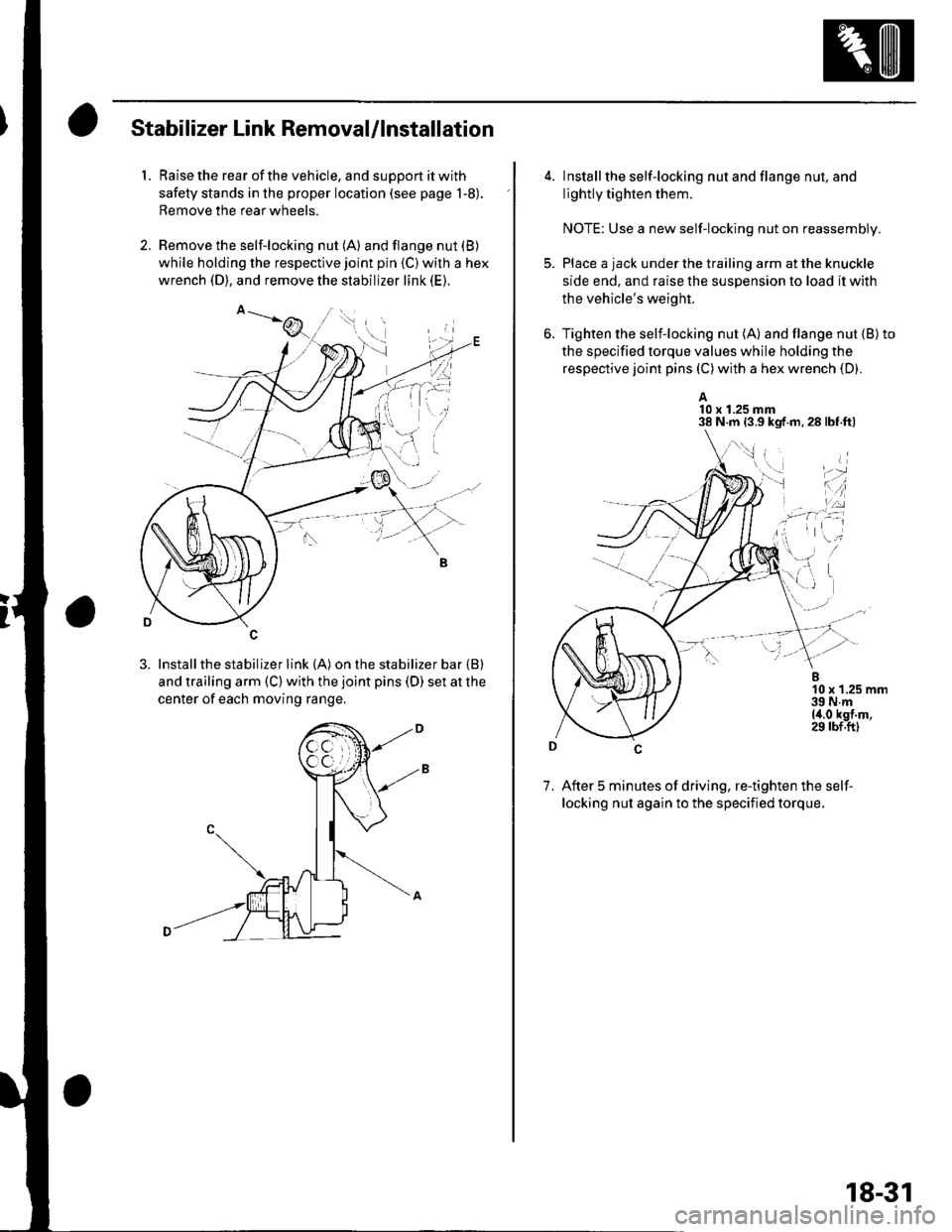
1. Raise the rear of the vehicle, and support it with
safety stands in the proper location (see page 1-8).
Remove the rear wheels.
2. Remove the self-locking nut (A) and flange nut (B)
while holding the respective joint pin {C) wilh a hex
wrench (D), and remove the stabilizer link (E).
3. Installthe stabilizer link (A) on the stabilizer bar {B)
and trailing arm (C) with the joint pins (D) set at the
center of each moving range,
4. lnstall the self-locking nut and flange nut, and
lightly tighten them.
NOTE: Use a new self-locking nut on reassembly.
Place a jack under the trailing arm at the knuckle
side end. and raise the suspension lo load it with
the vehicle's weight.
Tighten the selflocking nut (A) and flange nut {B)to
the specified torque values while holding the
respective joint pins (C) with a hex wrench (D).
A10 x 1.25 mm38 N.m 13.9 kgf.m,28lbf.ftl
7. After 5 minutes of driving, re-tighten the self-
locking nut again to the specified torque.
\,1 i
i'-r d
*l'',:
18-31
Page 590 of 1139

Rear Suspension
Upper Arm Removal/lnstallation
1.Raise the rear of the vehicle, and support lt with
safety stands in the proper location (see page 1-8).
Remove the rear wheels.
Place a floor jack under the trailing arm, and
support the suspensron.
Remove the flange bolt (A) and wheel sensor
harness bracket (B).
8 x 1.25 mm22 N.m (2.2 kgf.m,16 rbf.ft)
Remove the flange bolts (A), and remove the upper
arm {B).
12 x 1.25 mm59 N.m {6.0 kgf.m,ir3 lbf.ft)12 x 1.25 mm59 N.m 16.0 kgf m,43 tbf.ft)
18-32
5. Installthe upper arm in the reverse order of
renloval, and note these items:
. First install allthe suspension components and
lightly tighten the bolts and nuts, then place ajack under the trailing arm, and raise the
suspension to load it with the vehicle's weight
before fully tightening the bolts and nuts to the
specified torque values.. Tighten allthe mounting hardware to the
specified torque values.' Before installing the wheel, clean the mating
surface of the brake disc and the inside of the
wheel.. Check the wheel alignment, and adjust it if
necessary (see page 18-4).