2003 HONDA CIVIC Head removal
[x] Cancel search: Head removalPage 912 of 1139

Bulb Replacement
Headlight:
1. Disconnect the 3P connector (A) from the headlight.
Headlight {high/low): 60/55 W
f-rI-'-+lA- )/
Remove the rubber cover (B).
Pull the retaining spring (C) away from the bulb (D),
then remove the bulb.
Install a new bulb in the reverse order of removal.
Make sure the notches in the bulb align with the
tabs ln the headlight.
2.
Front Turn Signal Light:
Parking Light:
1. Remove the inner fender (see page 20-102).
2. Disconnectthe connectors (A) from the lights.
21W
5W
4.
Front turn signal light:
Parking light:
Turn the bulb sockets (B) 45'counterclockwise to
remove them from the headlight housing.
Installthe new bulb(s) in the reverse order of
removat.
22-81
Page 1019 of 1139
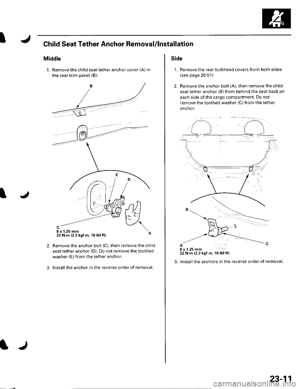
IChild Seat Tether Anchor RemovaUlnstallation
Middle
1. Remove the child seat tether anchor cover (A) in
the rear trim panel (B).
8 x 1.25 mm22 N m {2.2 ksf.m, 16lbf.ft)
,tltl
v\
2.
3.
Remove the anchor bolt (C), then remove the child
seat tether anchor (D). Do not remove the toothed
washer (E) from the tether anchor.
Installthe anchor in the reverse order of removal.
IJ
23-11
Side
1. Remove the rear bulkhead covers from both sides
(see page 20-51).
2. Remove the anchor bolt (A), then remove the child
seat tether anchor (B) from behind the seat-back on
each side ofthe cargo compartment. Do not
remove the toothed washer (C) from the tether
anchor.
AI18 x 1.25 mm22 N.m {2.2 kgt m. 16lbfft)
lnstallthe anchors in the reverse order of removal.
f-..- t".i..].-
Page 1126 of 1139
)
3.
4.
Cable Reel Replacement
Removal
1. Make sure the front wheels are aligned straight
ahead.
Disconnect the battery negative cable, and wait at
least 3 minutes.
Remove the driver's airbag {see page 23-113).
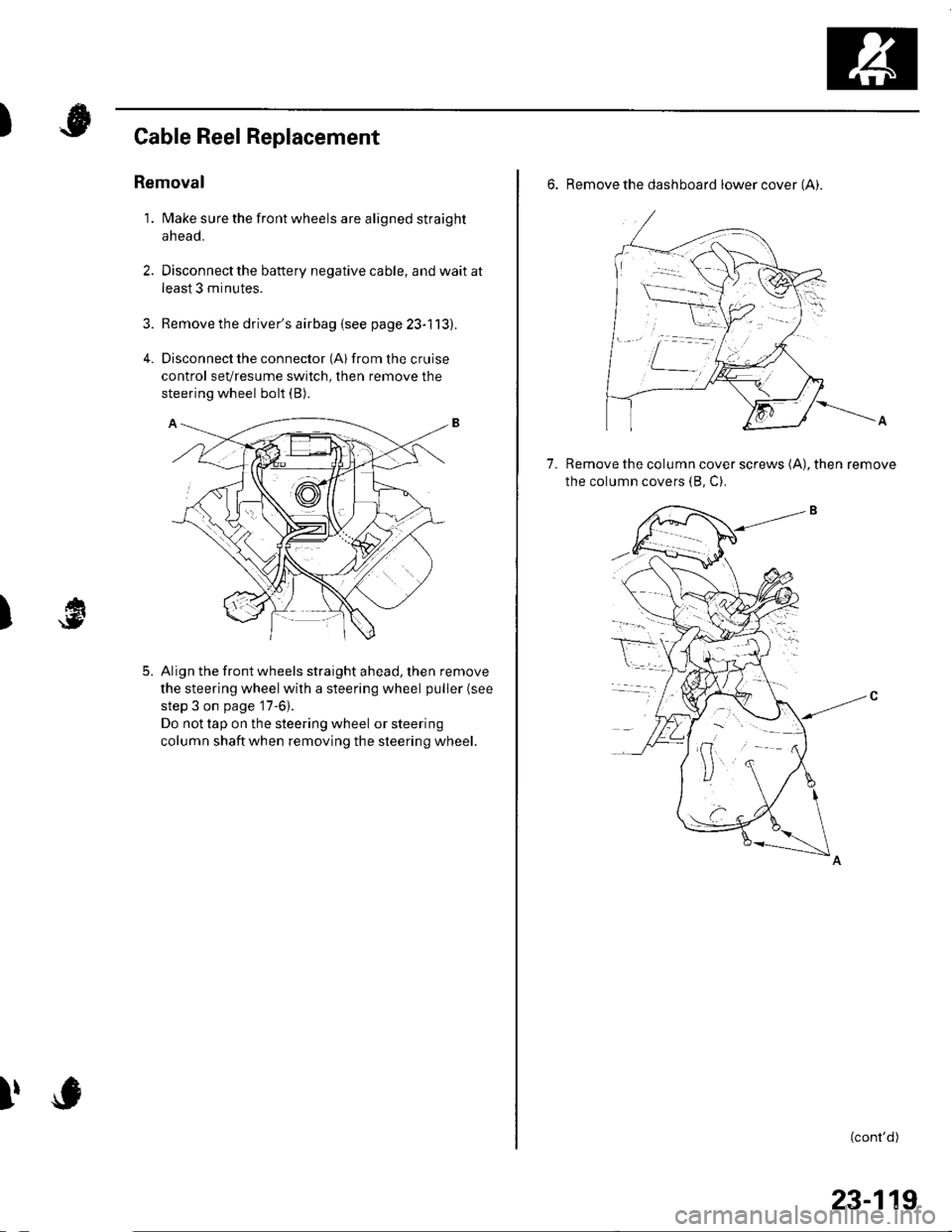
Disconnect the connector (Al from the cruise
control sevresume switch, then remove the
steering wheel bolt (B).
Align the front wheels straight ahead, then remove
the steering wheel with a steering wheel puller (see
step 3 on page '17-6).
Do not tap on the steering wheel or steering
column shaftwhen removing the steering wheel.
)
5.
I,
6. Remove the dashboard lower cover (Ai.
Remove the column cover screws (A), then remove
the column covers (8, C).
7.
(cont'd)
23-119
Page 1129 of 1139
sRs
SRS Unit Replacement
Removal
'1. Disconnect the battery negative cable, and wait at
least 3 minutes before beginning work.
2. Disconnect the driver's and front passenger's
airbag connectors (see page 23-21).
3. Disconnectthe side airbag connectors (see page
23-211.
4.Disconnect both seat belt tensioner connectors (see
page 23-22) and both seat belt buckle tensioner
connectors {see page 23-221.
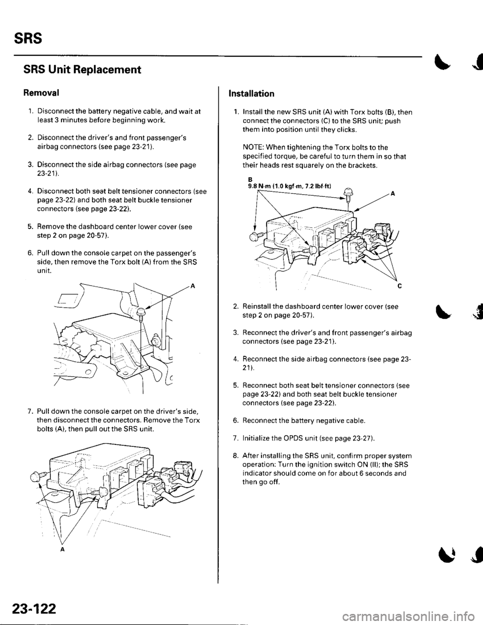
Remove the dashboard center lower cover (see
step 2 on page 20-57).
Pull down the console carpet on the passenger's
side, then remove the Torx bolt (A)from the SRS
unit.
7. Pull down the console carpet on the driver's side,
then disconnect the connectors. Remove the Torx
bolts (A), then pull out the SRS unit.
23-122
lnstallation
1, Installthe new SRS unit (A)with Torx bolts (B), then
connect the connectors {C) to the SRS uniu push
them into position until they clicks.
NOTE: When tightening the Torx bolts to the
specified torque, be careful to turn them in so that
their heads rest squarely on the brackets.
Reinstall the dashboard center lower cover (see
step 2 on page 20-57).
Reconnect the driver's and front passenger's airbag
connectors (see page 23-21]'.
Reconnect the side airbag connectors (see page 23-
211.
Reconnect both seat belt tensioner connectors (see
page 23-221 and both seat belt buckle tensioner
connectors (see page 23-22).
Reconnect the battery negative cable.
Initialize the OPDS unit (see page 23'27).
After installing the SRS unit, confirm proper system
operation: Turn the ignition switch ON (ll); the SRS
indicator should come on for about 6 seconds and
then go off.
4.
6.
8.
7.
9.8 N.m (1.0 kgf m, 7.2 lbf ft)
Page 1134 of 1139
Service Manual Index
(cont'dl
Brake System Indicator CircuitCircuit DiagramConventional Brake Components..... 19-9TroubleshootingABS/TCS Components .... ....... ...... 19-55
Bulb, GeugeRep|acemenl................ .. ............2263
Bulb, HeadlightReplacement ......................................... 22-A1
Bumper, FrontRemoval/1nsra11ation ............................ 20 85
Bumper, RearRemoval/lnstallation... ... . .....20.86
Combination Light SwilchTesVReplacement ..............................22 80
Connecting Rod BearingsRep|acement...................... .......-....7-8
Connecting Rod Boltsf nspection ....................-.-.-.-.................... 7 -24
Connecting RodsInspection ........,,.,.,...,.,.,.,.,,,,.,,,.,.,.,.,.,.,.,.. 7 5
Connectors(See first page of this Index)
Conventional Brake Component3Component Location Index ................... 19'3Troub1eshootin9 ..................................... 19-4
Cylinder Head AssemblyComponent Location Index ..................... 6-3Inspection ................................................. 6 6Removal ..........&�23Insta11alion .............................................. 6 39
Cylinder Head Cover8emova1 ..............-.-................................. 6-22Installation ..............................................6-41
Cylinder Head, BareInspecton..,.....,.
D
c
Cable ReelReplacement....................................... 23-1 19
CamshaftInspection .......................-...-................... 6-29
Cargo Area LightTesVRep1acement ................................ 22-97
CarpetReplacement.....-...-..... ... ......-.20-55
Ceiling Light-estrReplacement ................................ 22.96
Charging SystemComponent Location Index................... 4-20Circuit Diagram ...................................... 4-21
19-8
CoolantInspection .................. ..... .. 106Replacement................. ... . .. 10 6
Coolant Temperature Gat|geTroub1eshootin9................................... 22 64
Cooling SyslemComponent Location Index................... 10-2
Countershaft BearingsReplacement............... ..................... 13-42
Cowl CoverReplacement............... .. ..... ....20-95
CrankshaftRemoval .................................................. 7 -12
Repair ..................
Inspec(on,,,,,........1 14
Dampers. FrontReplacement................ ..................... 18 20
Oampers, RearRep1acement......................................... 18-34
Dash VentsBemoval/lnstallation .-.......................... 20-64
DashboardBemoval/1nsta11ation ............................ 20-66
Oashboard Center PanelRemoval/1nstaf 1ation ............................ 20 62
Dashboard Lower CoverRemoval/lnstallation ...................... 20-59, 63
Dashboard Under CoverRemoval/lnstallation ............................ 20 60
Diff erential Carrier Bearings, M/TRep1acement,,......,...,...,.,.,,,.,.,,,........,.,. 13-54
Ditferential Oil Seals, M/T8ep1acement......................................... 13-55
Differential Pinion Gears, M/TInspection .,....-,.,,,.,..,.-,.,.........,.,.,,, 13 53
OLC CircuitTroubleshooting ................................ 1 1-109
Door GlassRep1acement.,.,,,,,,,,,,,.,,,,,,,,,,.,.,.,.,.,,,,,,.,, 20-9Adjustment. .. .....................20-11
Door Glass WeathelstripsReplacement .............-.. . . . ..........-......20 10
Door LatchesReplacement ..........-.-.............................. 20-7
Door Lock ActuatorsTest ...................................................... 22-154
Door Lock Knob SwitchesTest -......... . . . - . . . . . . . . ......22-160
Door Lock SwitchesTest ........... ............................ ............. 22-160
Door Outer HandlesRep1acemen1 ........................................... 20-6
3
Child Seat Tether AnchorRemoval/lnstaf lat;on .. ........................ 23 11
CKP (Crankshaft Position) SonsorReplacement....................................... 1 1-116
ClutchComponentLocation 1ndex................... 12-3Rep1acemen1........................................... 12-9
Clutch InteYlock SwitchTest.....-........-...-............. ...---.-.......4-6
Clutch Master CylinderReplacement........................................... 12 5
clutch PedalAdjustment ............................................. 12 4
Clutch Pedal Position SwitchTest.,.,,,,,.,,,.,.,,,,,,.,.,,,,,,,,,.,,,,,.. ......445
lnstallation.................. . ..... .....1-24
Crankshalt Main BearingsReplacement........-.-.................................. 7-6
CrankshaftOil Seal,Transmission End1nstanation .............................................. 7 28
Crankshafl PulleyRemoval/lnstallation -..................-.......... 6-1 1
Cruise Control Actuator
Troubleshooting
Clutch Slave CylindorBeplacemeit...
...................... 4-43
.......4-22
Test
12-1
RepIacement........................................... 4-44
Cruise Control Actuator CableAdjustment ............................................. 4 45
Cruise Control Main SwitchTesVRep1acement .................................. 4 42
Cruise Control Set/Resume/Cancel SwitchTesVRep1acement .................................. 4 42
Cruise Control SystomComponent Localion Inde\................... 4-36Circuit Diagram ....-................................. 4 37
Cruise Control UnitInputTest.............................. .. ...4,40CMP {Camshaft Positionl Senso]Replacement....-...-.............................. 1 1-128
CMP (TDC) SensorsReplacement............-.......................... 1 1 1 14
Page 1136 of 1139
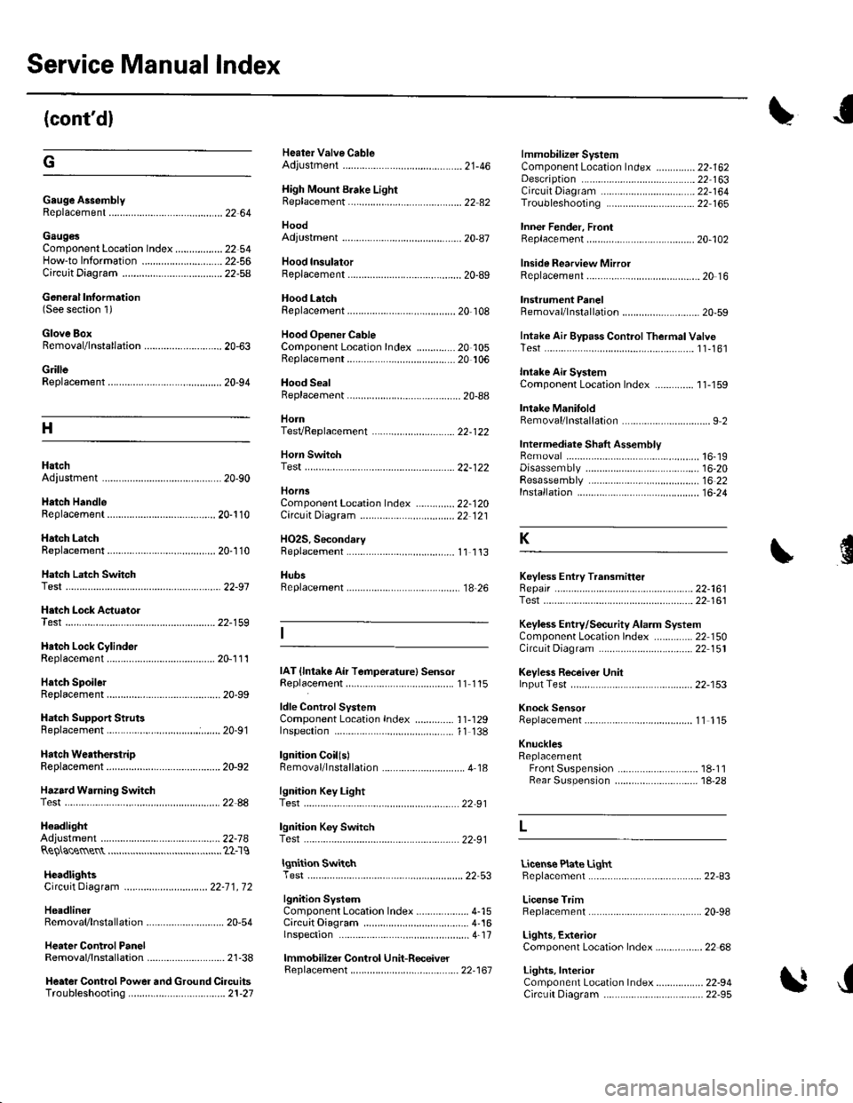
Service Manual Index
(cont'dl
Gauge A3semblyReplacement......................................... 22 64
Gaug€sComponent Location Index ..........-...... 22 54How-to lnformation ........................22-56Circuit Diagram22-54
Heater Valve CableAdjustment ...................... .................... ?1-46
High Mount Brake Light8ep|acement......................................... 22 82
Hood
lmmobilizer SystemComponent Location In dex .............. 22-162
\
G
Description
Genoral Information(See seclion 1)
Glove BoxRemoval/1nsta11ation .......................-.... 20-63
GrilleReplacement...........-............................. 20-94
Hood lnsulatorReplacement......................................... 20-89
Hood LatchRep1acement................... ..........20 108
Hood Opener CableComponentLocation Index ..............20 105Replacement ................ . . ........... .....20 106
Hood SealBeplacement.-...........................-........... 20-88
HornTesVReplacement . . ................ ...... 22-122
CircuitDiagram ...........................22-164Troubleshooting ............................ 22,165
Inner Fender, FronlRepf acemenl....................................... 20-102
Inside Rearview MirrorReplacement..........-.............................. 20 16
Instrument PanelRemoval/1nsta11ation................. ....... 20-59
Intake Air Bypass ControlThermal ValveTesr................................ ..... ..11-161
Intake Air SystemComponent Location Index ...-.-........ 11-159
Intake ManitoldRemoval/1nsta11ation ................................ I 2
lntermediate Shaft AssemblyRemova1 ................-.-...-......................... 16-19Disassemb|y................... ... ......-.... 16,20Resassemb|y ........................................ 16 22Installation .........-...-.............................. 16-24
Keyless Entry Transmitter
Adjuslment
H
Adiustment .......
Hatch Handle
Horn SwitchTest ............-........
HornsComponent Location IndexCirc!it Diagram
H02S. SecondaryReplacement
..............22-120Replacement
22-122
22 12120-110
20-'110Hatch LatchReplacement$
K
Hatch Latch Switch
.... 11 113
HubsReplacement. ... .................................. 1A 26Test
Test
Replacement
Hatch Support StrutsBeplacement.....
Hatch WeatherstrioReplacement....
Hazard Warning Switchtest
ldle ControlSystemComponentLocation Index .............. 11-129Inspection,.,.........-.......,.,.,,,,,,.,,,.,.,..... 1'l 138
lgnition CoillslBemoval/lnstallation ...............-.............. 4 18
22-161Test ...................................................... 22 161
Keyless Entry/Security Alarm SystemComponenl Location Index .............. 22 150Circuil Diagram ................. . .............. 22 151
Keyless Receiver Unitlnput Test ............................................ 22-153
Knock SensorReplacement......-................................ 1 1 115
KnucklesReplacementFront Suspensron ............................. 18-1 1Rear Suspension ........ .................-... 18-28
Repair ...............
H.tch Lock Actuator22-159
Hatch Lock CylinderRep|acement....................................... 20,111
Hatch SpoilerIAT {lntake Air Temperature} SensorReplacement.,.........-...'11 115
20-91
20-92
.................... 22_88lgnition Key LightTest,,.,,,,.,...,......-.
H6adlightAdjustmentlgnition Key Switch
....................... 22-91
....................... 22-91..22-78TestReQ\ace$entlgnition SwitchTest .,,,.,.,.,,,,.,.,.......22-53License Plate LightReplacement...........-... - ... .....22-83
License TrimReplacement..................-...-..........-....... 20-98
Lights, ExteriorComponent Localion Index.................22 68
Lights,InteriorComponent Location Index................. 22-94CircuitDiagram .. .. ...... .... 22-95
HcadlightsCircuit Diagram .............................. 22-71, 72
HeadlinerRemoval/lnstallalion ............................ 20-54
Heater ControlPanelRemoval/1nsta11ation ............................ 21-38
Heater Control Power and Ground CircuitsTroubfeshooting......... .......................21-27
lgnition SystemComponent Location Index ................... 4-15CircuitDia9ram .................................... 4'161nspection ............................................... 4-17
lmmobilizer Control Unit-Receiver
J
22-161