Page 4 of 1139

General Information
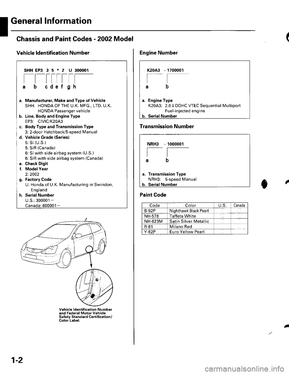
Chassis and Paint Codes - 2OO2 Model
Vehicle ldentffi cation Number
SHHEP3 35'2 U 300001
[[tttrtF
cdef gh
a. Manufacturer, Make and Type of Vehicle
SHH; HONDAOFTHE U.K. MFG., LTD. U.K.
HONDA Passenger vehicle
b. Line, Body and Engine Type
EP3: CIVIC/K20A3
c. Body Type and Transmission Type
3: 2-door HatchbacUs-speed Manual
d. Vehicle Grade lSeries)
5: Si {U.S.}
5; SiR (Canada)
6: Si with side airbag system (U,S.)
6: SiR with side airbag system (Canada)
e. Check Digit
l. ModelYear
2i 2002
g. Factory Code
U: Honda of U.K. Manufacturing in Swindon,
E ng land
h. Serial Number
U.S,: 300001 -
1-
V€hicle ldentif ication Numbo.and Federal Motor VehicleSaf ety Standard Certif ication/Color Label.
1-2
I
1700001K2OA3
a
a. Engine Type
K20A3: 2.0 0 DOHC VTEC Sequential Multiport
Fuel-injected engine
b. Serial Number
Engine Number
Transmission Number
Paint Code
CodeColoru.s.Canada
B-92PNiqhthawk Black Pearl
NH-578Taffeta White
NH-623MSatin Silver lvletallic
R-81Milano Red
Y-62PEuro Yeliow Pearl
NBH3
I
a
Transmission Type
NRH3; s-sDeed Manual
1000001
t0
Page 5 of 1139

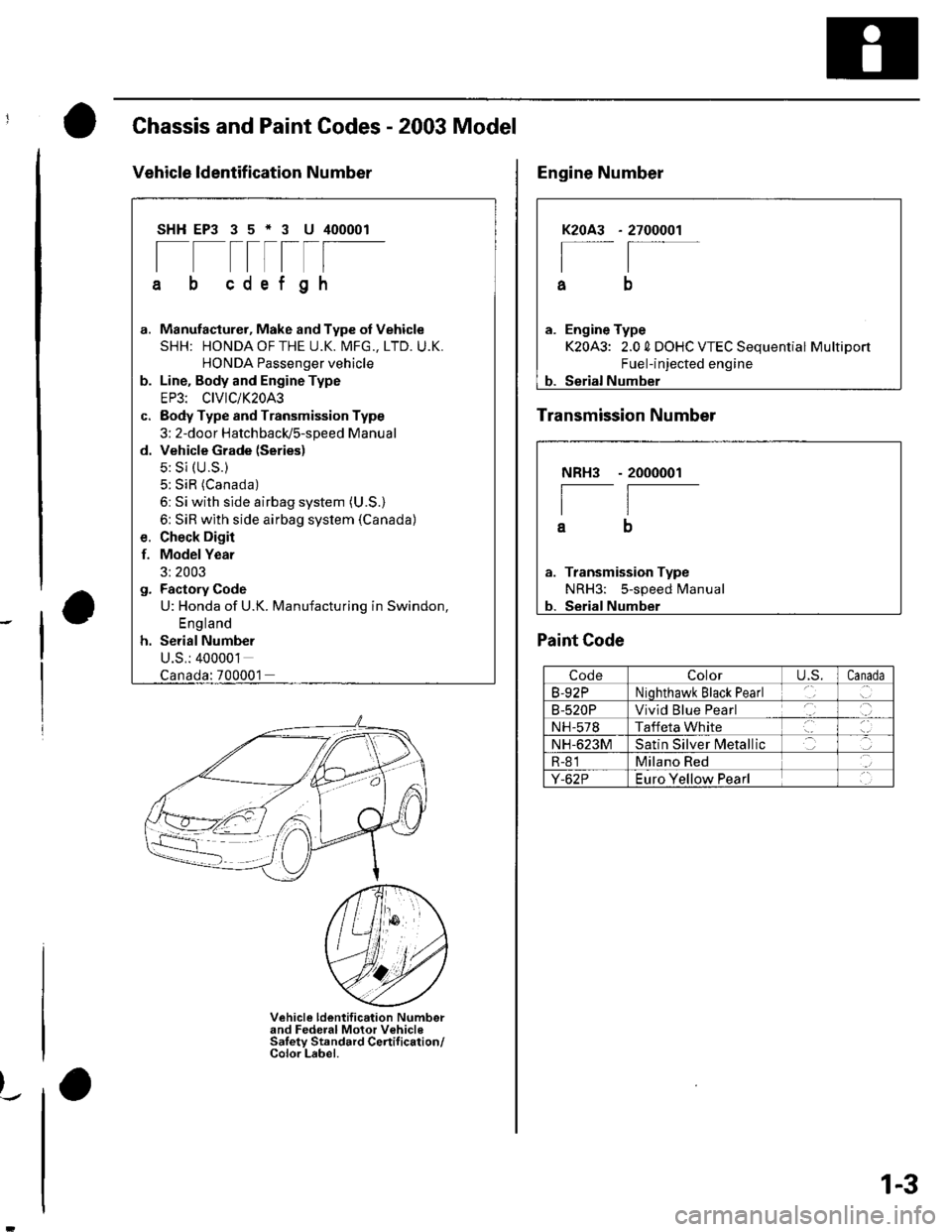
Chassis and Paint Codes - 2003 Model
Vehicle ldentif ication Number
SHHEP3 35*3 U 400001
[--t-rlF
cdef gh
G.
d.
Manufacturer, Make and Type of Vehicle
SHH: HONDAOFTHE U.K. MFG., LTD. U.K.
HONDA Passenger vehicle
Line. Body and Engine Type
EP3: CIVIC/K20A3
Body Type and Transmission Type
3: 2-door HatchbacldS-speed Manual
Vehicle Grade (Series)
5: Si (U.S.)
5: SiR (Canada)
6: Si with side airbag system (U.S.)
6: SiR with side airbag system (Canada)
Check Digir
Model Year
3: 2003
Factory Code
U: Honda of U.K. Manufacturing in Swindon,
England
Serial Number
U.S.: 400001
f.
:700001
Vehicle ldentification Numberand Federal Motor VehicleSaletv Standard Certif ication/Color Label.
)_.
2700001K2OA3
I
a
a. Engine Type
K20A3: 2.0 0 DOHC VTEC Sequential Multiport
Fuel-injected engine
b. Serial Number
Engine Number
Transmission Number
NRH3
I
a
Transmission Type
NRH3: 5-speed Manual
Serial Number
- 2000001
Paint Code
CodeColorU,S.Canada
B-92PNiohthawk Black Pearl
B-520PVivid Blue Pearl
NH-578Taffeta White
NH-623MSatin Silver N4etallic
R-81Milano Red
Y-62PEuro Yellow Pearl
1-3
Page 23 of 1139

L
v
2-11
Design Specifications
O
o
o
|temMeasurementOualificationSpecilication
DIMENSIONSOveralllength4,210 mm {165.8 in.)
Overallwidth1,695 mm 166.7 in.)
Overallheight1,440 mm (56.7 in.)
2,570 mm (101.2 in.)
Trackrront1,470 mm (57.9 in.)
Rear'1,470 mm (57.9 in.i
Ground clearance152 mm (5.98 in.)
Seating capacityfour {4)
wEtGt-iT {u.s.A.)Gross Vehicle Weight Rating
(GVWR)
3,660 rbs
WEIGHT
(CANADA)
Gross Vehicle Weight Rating
{GVWR)
1,660 kg
ENGIN ETvpeWater cooled. 4 stroke DOHC V-EC engin(
Cylinder arrangementInline 4'cylinder, transverse
Bore and stroke86 x 86 mm (3.39 x 3.39 in.)
Displacement1,998 cm'(122 cu in.)
Compression ratio9.8
Valve trainChain drive. DOHC VTEC 4 valves per cylinder
Lubrication systemForced, wet sump, with trochoid pumP
Oil pump displacementAt 6,000 engine
rpm
54.3 0 (57.4 US qo/minute
Water pump displacementAt 3,400 engine82 0 (87 US qt)/minute
F!el requiredUNLEADED gasoline with 86 pump octane number or higher
STARTERTvpeGear reduction
Normaloutput
Nominalvoltage12V
Hour rating30 seconds
Direction of rotationClockwise as viewecl from gear end
CLUTCHClutch tvpeSinqle plate dry, diaphragm spring
Clutch friction material surface area174 cm'{26.97 sq in.)
I\,1AN UAL
TRANSMISSION
TvpeSvnchronized, s-speed forward, 1 reverse
Primarv reductionDirect 1:1
Gear ratiolst3.062
2nd1.769
3rd1.212
4th0.921
5th0.738
Reverse3.583
FinalreductionTypeSinole helicalgear
Gear ratio4.164
Page 59 of 1139

Gharging System
Charging Circuit Troubleshooting (cont'd)
6. Start the engine. Hold the engine at 3,000 rpm with
no load (in Neutral) until the radiator fan comes on,
then let it idle.
7. Raise the engine speed to 2,000 rpm, and hold it
there.
8. Turn the headlights (high beam) on, and measure
voltage at the under-hood fuse/relay box terminal.
ls the voltage between 13.9 and 15.1 v?
YES-Go to step 9.
NO Repair or replace the alternator components
(see page 4-30).1
9. Read the amperage at '13.5 V.
NOTE: Adjust the voltage by turning the blower
motor, rear window defogger, brake lights. etc. ON.
ls the amperage 604 ot morc?
YES-Alternator/regulator operation is OK. I
NO Repair or replace the alternator components(see page 4-30).1
4-24
\,
Alternator Control System Test
NOTE: After troubleshooting, perform the engine
control module (ECM) idle learn procedure (see page
11-139).
1 . Check for proper operation of the electrical load
detector (ELD) by checking the malfunction
indicator lamp (MlL) (see page 1 l-3). lf a DTC is
present, diagnose and repair the cause before
continuing with this test.
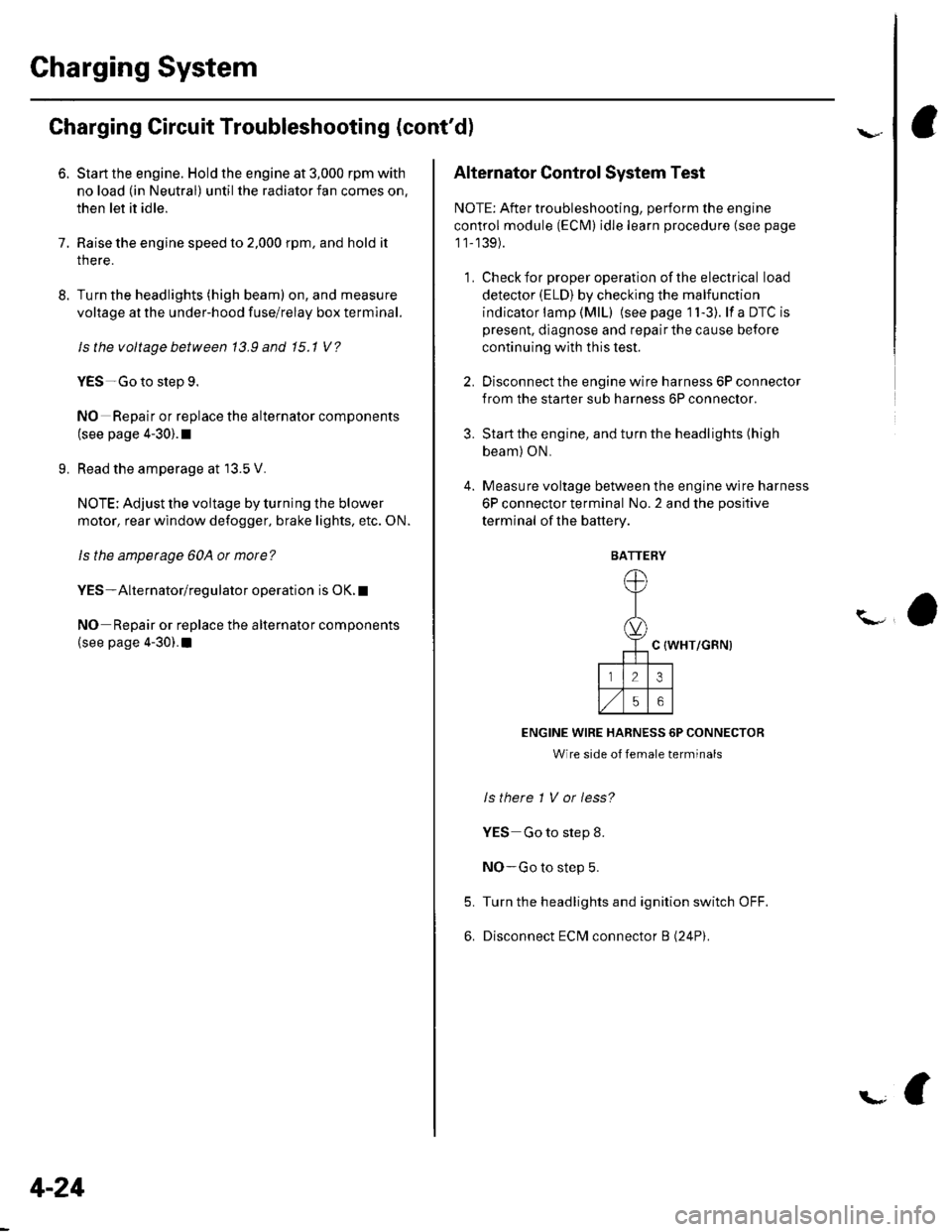
2. Disconnect the engine wire harness 6P connector
from the starter sub harness 6P connector.
3. Start the engine, and turn the headlights (high
beam) ON,
4. Measure voltage between the engine wire harness
6P connector terminal No. 2 and the positive
terminal of lhe battery.
C {WHT/GRN)
ENGINE WIRE HARNESS 6P CONNECTOR
Wire side of female terminals
ls there 1 V or less?
YES Go to step 8.
NO-Go to step 5.
Turn the headlights and ignition switch OFF.
Disconnect ECM connector B (24P).
5.
6.
BATTERY
Page 96 of 1139

\
Engine Mechanical
Cylinder Head
Special Tools
Comoonent Location Index
Engine Compression Inspection
VTEC Rocker Arm Test ........... ............ 6-7
VTC Actuator Inspection .................... 6-8
Valve Clearance Adjustment ............. 6-9
Crankshaft Pulley Removal and Installation .............. 6-11
Cam Chain Removal ........................... 6-12
Cam Chain Installation ....................... 6-15
Auto-Tensioner Removal/1nsta11ation ......................... 6-19
Chain Case Oil Seal Installation ........ 6-21
Cyf inder Head Cover Removal .......... 6-22
Cylinder Head Removal ..................... 6-23
WC Actuator. Exhaust Camshaft Sorocket
Repf acement .........6-24
Cylinder Head Inspection for Warpage ...................... 6-25
Rocker Arm Assembly Removal ................................. 6-26
Rocker Arms and Shafts
Disassembly/Reassembly .............. 6-27
Rocker Arms and Shafts Inspection ............................ 6-28
Camshaft Inspection .......................... 6-29
Valves, Springs, and Valve Seals Removal ................ 6-31
Valve Insoection ...................... ........... 6-32
Valve Stem-to-Guide Clearance Insoection ............... 6-32
Valve Guide Reolacement ................. 6-33
Valve Seat Reconditioning ................ 6-35
Valves, Springs, and Valve Seals Installation ............ 6-37
Rocker Arm Assemblv Installation .... 6-38
Cvlinder Head Installation ........................................... 6-39
Cylinder Head Cover Installation ...... 6-41
6-2
6-3
b-t'
Page 97 of 1139
Cylinder Head
aSpecialTools
I
'a- ti-- - -- -i
',..)-)--' -
o
..'.,i2
.<:'':'v''
5'r'
a
/":
-- -'''
't'tY-,l
- 1jr- r--- - l-: ,.
@o
,- '' ,)
,.-/ r--\
a:-t'"
Lq-,
ol?
..#
..a:-"
a,/'/'
@@OD
Ref. No. Tool NumberDescription Oty
O OTAAJ.PNAA'IOO
.D OTHAH-PJ7O1OB
o I oz..rae-oot ozoa
@ 07JAB-0010204
o 07NAB-0010404
G) 07VAE-001010A
OTZAJ.PNAAlOO
E] OTZAJ-PNAA2OO
O I 07ZAJ-PNAA300
tro 07742-0010100
@ 07746-001o4oo(D 07749-0010000
Air Pressure Regulator
Valve Guide Reamer, 5.5 mm
Socket, 19 mm
Holder Handle
Holder Attachment, 50 mm
Valve Spring Compressor Attachment
VTEC Air Adapter
VTEC Alr Stopper
Air Joint Adapter
Valve G uide Driver,5.5 mm
Attachment, 52 x 55 mm
Driver
1
1
1
1
1
1
2
1
1
6-2
Page 102 of 1139

WEC Rocker Arms Test
Special Tools Required. Air pressure regulator 07AAJ-PNAA100. VTEC air adaoter 07ZAJ-PNAA100. WEC air stoDoer 07ZAJ-PNAA200. Air joint adapter 07ZAJ-PNAA300
1. Remove the cylinder head cover (see page 6-22).
2. Set the No. 1 piston at top dead center (TDC) (see
step 1 on page 6-12).
3. Verify that the intake primary rocker arm (A) moves
independently of the intake secondary rocker arm
(B).
. lf the intake primary rockerarm does not move,
remove the primary and secondary rocker arms
as an assembly and check that the pistons in the
secondary and primary rocker arms move
smoothly. lf any rocker arm needs replacing,
replace the primary and secondary rocker arms
as an assemblv, and test.. lfthe intake primary rocker arm moves freely, go
to step 4.
6.
Repeat step 3 on the remaining intake primary
rocker arms with each piston at TDC. When all the
primary rocker arms pass the test, go to step 5.
Check that the air pressure on the shop air
compressor gauge indicates over 400 kPa
(4 kgflcm', 57 psi).
Inspect the valve clearance (see page 6-9).
Remove the sealing bolt (A)from the relief hole,
and install the VTEC air stopper (B).7.
OTAAJ.PNAAlOODOTZAJ-PNAA3OO
Remove the No. 2 and No. 3 camshaft holder bolts,
and installthe VTEC air adapters (C) finger-tight.
Connect the air joint adapter (D), and air pressure
regulator with a 0-100 psi gauge (E).
(cont'd)
OTZAJ.PNAAlOO
6-7
Page 123 of 1139
Cylinder Head
1.
2.
Rocker Arms and Shafts Inspection
Remove the rocker arm assembly (see page 6-26).
Measure the diameter of the shaft at the first rocker
location.
3. Zero the gauge (A) to the shaft diameter.
6-28
\
4. Measure the inside diameter ofthe rocker arm, and
check it for an out-of-round condition.
Rocker Arm-to-Shaflt Clearance:
Standard lNew):
lntake: 0.025 0.052 mm(0.0010 0.0020 in.)
Exhaust: 0.018 0.056 mm
(0.0007 0.0022 in.)
Service Limit: 0.08 mm (0.003 in.)
5. Repeat for all rockerarms and both shafts. lfthe
clearance is over the Ilmit. replace the rocker shaft
and all overtolerance rocker arms. lf any VTEC
rocker arm needs replacement, replace the rocker
arms (primary and secondary) as a set.
6. Inspect the rocker arm pistons {A}. Push each
piston manually.
lf it does not move smoothly, replace the rocker
arm set.
NOTE: Apply oil to the pistons when reassembling.
,,,@@
(\.
(