Page 109 of 1139
Cylinder Head
14.
Cam Chain Removal (cont'd)
Loosely install the crankshaft pulley.
Turn the crankshaft counterclockwise to compress
the auto-lensioner,
Align the holes on the lock (A) and the auto-
tensioner (B), then insen a 1.5 mm (0.06 in.)
diameter pin (C) into the holes. Turn the crankshaft
clockwise to secure the Din.
t5.
6-14
\-
(\
16. Remove the auto-tensioner.
a
17. Remove the cam chain guide B.
gffi
llll
UU
Page 114 of 1139
19.
20.
lnstall the variable valve timing control (VTC) oil
control solenoid valve (see step 1 on page 11'127).
Connect the crankshaft position (CKP) sensor
connector {A) and VTC oil control solenoid valve
connector (B).
21. Install the crankshaft pulley (see page 6-12).
22. Installthe cylinder head cover (see page 6-41).
23. Installthe drive belt.
24. Installthe splash shield.
€D@
Auto-Tensioner RemovaU
lnstallation
Removal:
1. Remove the chain case cover.
Turn the crankshaft counterclockwise to compress
the auto-tensroner.
{cont'd)
6-19
Page 115 of 1139
Gylinder Head
Auto-Tensioner Removal/l nstallation
3. Align the holes on the lock (A) and the auto-
tensioner (B), then insert a 1.5 mm (0.06 in.)
diameter pin (C) into the holes. Turn the crankshaft
clockwise to secure the oin.
4. Remove the auto-tensioner.
6-20
\-
(cont'dl
Installation:
1. Install the auto-tensioner.
\
6x1.0mm12 N.m {1.2 kgt.m, 8.7 lbt.tt)
Remove the pin from the auto-tensioner.
a\
Page 117 of 1139
Gylinder Head
Cylinder Head Cover Removal
1. Remove the intake manifold cover.
2. Remove the four ignition coils (see page 4-'18).
3. Remove the dipstick (A) and breather hose (B).
6-22
\-
\
4, Remove the cylinder head cover
V:t :;t 1
|
,'.i/
(
(
Page 118 of 1139

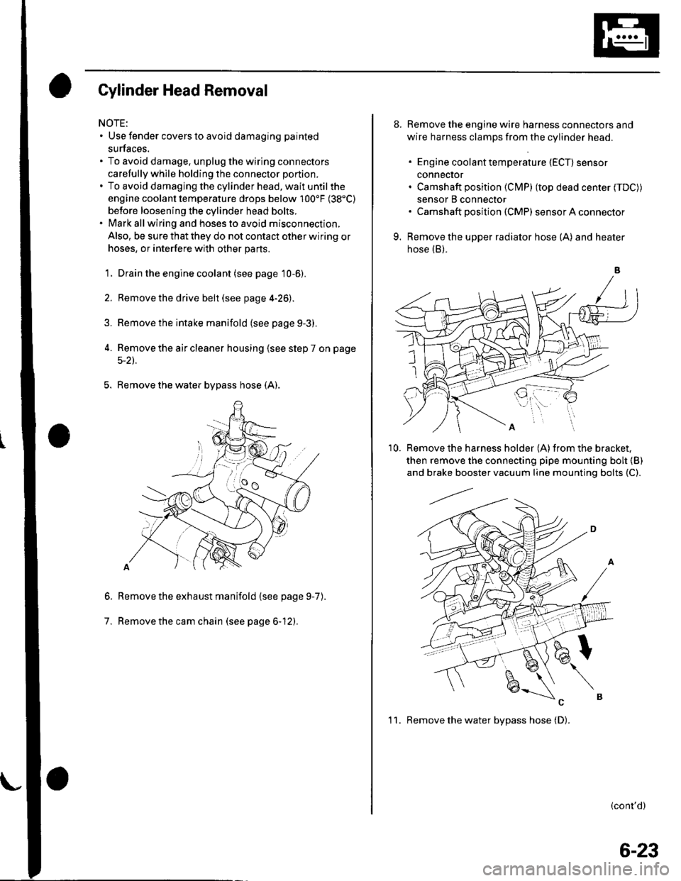
Gylinder Head Removal
NOTE:. Use fender covers to avoid damaging painted
surfaces.
To avoid damage, unplug the wiring connectors
carefully whlle holding the connector portion.
To avoid damaging the cylinder head, wait until the
engine coolant temperature drops below 100'F (38"C)
betore loosening the cylinder head bolts.
Mark all wiring and hoses to avoid misconnection.
Also, be sure that they do not contact other wiring or
hoses, or interfere with other parts.
'1.
2.
3.
Drain the engine coolant (see page 10-6).
Remove the drive belt (see page 4-26).
Remove the intake manifold {see page 9-3).
Remove the air cleaner housing (see step 7 on page
5-2t.
5. Remove the water bypass hose (A).
Remove the exhaust manifold (see page 9-7
Remove the cam chain (see page 6-12).
6.
7.
).
8. Remove the engine wire harness connectors and
wire harness clamps from the cylinder head.
. Engine coolant temperature (ECT) sensor
conneclor. Camshaft position (Cl\4P) (top dead center (TDC))
sensor B connector. Camshaft posilion (CMP) sensor A connector
9. Remove the upper radiator hose (A) and heater
hose (B).
'10. Remove the harness holder (A)from the bracket,
then remove the connecting pipe mounting boh {B)
and brake booster vacuum line mounting bolts {C).
(cont'd)
1 1. Remove the water bvpass hose (D).
6-23
Page 119 of 1139
Cylinder Head
tJ.
Cylinder Head Removal (cont'd)
Remove the rocker arm assembly (see page 6-26).
Remove the cylinder head bolts. To prevent
warpage, unscrew the bolts in sequence 1/3 turn at
a time; repeat the sequence until all bolts are
loosened.
CYLINDER HEAD BOLTS LOOSENING SEQUENGE:
14. Remove the cylinder head.
6-24
VTC Actuator, Exhaust Camshaft\
Sprocket Replacement
Removal:
1. Remove the cam chain (see page 6-12).
2. Hold the camshaft with an open-end wrench, then
loosen the variable valve timing control (VTC)
actuator mounting bolt and exhaust camshaft
sprocket mounting bolt.
Remove the VTC actuator and exhaust camshaft
sprocket.
I\(
I
Page 121 of 1139
Cylinder Head
'1.
2.
Rocker Arm Assembly Removal
Remove the cam chain (see page 6-12).
Loosen the rocker arm adjusting screws (A),
A
3. Remove the camshaft holder bolts. To Drevent
damaging the camshafts, unscrew the bolts two
turns at a time, in a crisscross pattern.
CAMSHAFT HOLDER BOLTS LOOSENING
SEOUENCE:
6-26
\-
4.Remove the cam chain guide B, camshaft holders,
and camshafts.
Insert the bolts (A) Into the rocker shaft holder, then
remove the rocker arm assembly (B).5.
{
Page 126 of 1139
Valves, Springs, and Valve Seals Removal
Special Tools Bequired
Valve spring compressor attachment 07VAE-001010A
ldentify the valves and valve springs as they are
removed so that each item can be reinstalled in its
original position.
1. Remove the cylinder head (see page 6-23).
2. Using an appropriate-sized socket (A) and plastic
mallet {B), lightly tap the valve retainer to loosen
the valve keepers.
Install the spring compressor. Compress the spring,
and remove lhe valve keepers.
4. Installthe valve guide seal remover.
5.the valve seal.Remove
\
6-31