Page 139 of 1139

Engine Mechanical
Engine Block
Soecial Tools ............. 7 -2
Comoonent Location Index ......................................... 7-3
Connecting Rod and Crankshaft End Play
InsDection .............. 7-5
Crankshaft Main Bearing Replacement ...................... 7-6
Connecting Rod Bearing Replacement ...................... 7-8
Oil Pan Removal ....................... .......... 7-11
Crankshaft and Piston Removal ........ 7-12
Crankshaft Inspection ........................ 7-14
Block and Piston Insoection ........................................ 7-15
Cyfinder Honing ............ .".................... 7 -'17
Piston, Pin and Connecting Rod Replacement .......... 7-18
Piston Ring Replacement ................... 7 -21
Piston lnstallation .................... ........... 7-23
Connecting Rod Bolt Inspection .......' 7 -24
Crankshaft lnstallation .....................'. 7-24
Oil Pan lnstallation .................. ........... 7 -27
Transmission End Crankshaft Seal
lnstallation-ln Car ................... ........' 7 -28
Page 142 of 1139
Engine Block
Component Location Index (cont'd)
/^., \
D->< | _,-ersroru nrrucs
Y1 l-"t Benlacement. Page 7-21
rkrej, I
ffil
rG AalQ
[=l^oJ
\
PISTONRemoval, page 7-'12Measurement, page 7-15
PISTON PINRemoval, page 7-18Inspection, page 7-19Installation, page 7,20
f,
6
CONNECTING RODEnd play, page 7-5Small end measurement, page 7-19
CONNECTING ROD
ENGINE BLOCKCylinder bore inspection, page 7-'15Warpage inspection, page 7-15Cylinder bore honing, page 1-11Ridge removai, step 13 on page 7-13
(\
CONNECTING ROD BOLTlnspectaon, page 7 24
7-4
Page 150 of 1139
Engine Block
Crankshaft and Piston Removal
1. Remove the engine assembly (see page 5-2).
2. Remove the transmission (see page 13-4).
3. Remove the oil pan (see page 7-1 1).
4. Remove the oil pump {see page 8-9).
5. Remove the cylinder head (see page 6-23).
6. Remove the baffle plates.
7. Remove the 8 mm bolts.
E
7-12
8. Remove the bearing cap bolts. To prevent warpage,
unscrew the bolts in sequence 1/3 turn at a time:
repeat the sequence until all bolts are loosened.
Remove the lower block and bearings, Keep all
bearings in order.
\L
(
Page 151 of 1139

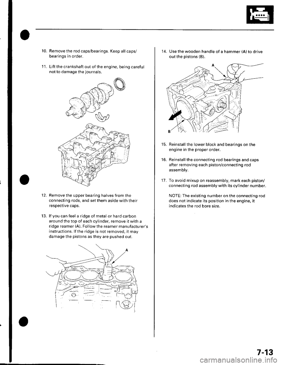
10.Remove the rod caps/bearings. Keep all caps/
bearings in order.
Liftthe crankshaft out ofthe engine, being careful
not to damage the journals.
Remove the upper bearing halves from the
connecting rods. and set them aside with their
respective caps.
lf you can feel a ridge of metal or hard carbon
around the top of each cylinder, remove it with a
ridge reamer {A). Followthe reamer manufacturer's
instructions. lf the ridge is not removed, it may
damage the pistons as they are pushed out.
11.
t.J.
14. Use the wooden handle of a hammer (A) to drive
out the pistons (B).
Reinstall the lower block and bearings on the
engine in the proper order,
Reinstallthe connecting rod bearings and caps
after removing each piston/connecting rod
assembly.
To avoid mixup on reassembly. mark each piston/
connecting rod assembly with its cylinder number.
NOTE: The existing number on the connecting rod
does not indicate its position in the engine, it
indicates the rod bore size.
15.
to.
17.
7-13
Page 153 of 1139

1.
Block and Piston Inspection
Remove the crankshaft and pistons (se e pageT -121.
Check the piston for distortion or cracks,
Measure the piston diameter at a point I1 mm {0.4in.) from the bottom of the skirt. There are two
standard-size pistons (No Letter or A, and B). The
letter is stamped on the top of the piston. Letters
are also stamped on the block as cylinder bore
stzes.
Piston Diameter:
Standard (Newl:
No Letter {or A): 85.980 85.990 mm(3.3850 3.3854 in.)
B: 85.970-85.980 mm(3.3846-3.3850 in.)
Service Limit:
No Lefter lor A): 85.930 mm (3.3831 in.)
B: 85.920 mm 13.3827 in.)
Oversize Piston Diameter:
0.25: 86.230-85.240 mm (3.3949 -3.3953 in.l
4. Measure wear and taper in direction X and Y at
three levels in each cylinder as shown. lf
measurements in any cylinder are beyond the
oversize bore service limit. replace the block. lf the
block is to be rebored, refer to step 7 after reboring.
Cylinder Bore Size
Standard (New):
A or l: 86.010 86.020 mm
13.3862 3.3866 in.)
B or ll: 86.000 86.010 mm(3.3858 3.3862 in.)
Service Limit: 86.070 mm (3.3886 in.)
Oversize:
O.25t 96.250 86.260 mm (3.3957 3.3961 in.)
Reboring limit: 0.25 mm (0.01 in.l max.
Bore Taper:
Limit: (Difference between first and third
measurement) 0.05 mm (0.002 in.)
FirstMeasurement
SecondMeasutement
ThirdMeasurement
(cont'd)
7-15
6 mm {0.2 in.}
6 mm {0.2 in.}
Page 154 of 1139
Engine Block
Block and Piston Inspection (cont'd)
Scored or scratched cylinder bores must be honed.
Check the top of the block for warpage. Measure
along the edges and across the center as shown.
Engine Block Warpage
Standard lNew): 0.07 mm (0.003 in.) max.
Service Limit: 0.10 mm (0.004 in.l
PRECISION STRAIGHT EDGE
7-16
\
7. Calculate the difference between the cylinder bore
diameter and the plston diameter. lf the clearance
is near or exceeds the service limit, inspect thepiston and cvlinder block for excessive wear.
Piston-to-Cylinder Clearance
Standard lNew): 0.020 0.040 mm
{0.0008 0.0016 in.)
Service Limit: 0.05 mm (0.002 in.l
++ PISTON-TO-CYLINDERCLEARANCE
\
(
Page 156 of 1139
Engine Block
Piston, Pin, and Connecting Rod Replacement
Disassembly
1. Remove the piston from the cylinder block (see
page 7 -12).
2. Apply engine oilto the piston pin snap rings (A),
and turn them in the ring grooves until the end
gaps are lined up with the cutouts in the piston pin
bores (B).
NOTE; Take care not to damage the ring grooves.
Remove both snap rings (A). Start at the cutout in
the piston pin bore. Remove the snap rings
carefully so they do not go flying or get lost. Wear
eve protection.
7-18
\"
4.Heat the piston and connecting rod assembly to
about 158'F (70"C), then remove the piston pin.
(\
Page 157 of 1139
v
Inspection
NOTE: Inspect the piston, piston pin, and connecting
rod when they are at room temperature.
1. Measure the diameter of the piston pin.
Piston Pin Diameter
Standard (New): 21.961 21.965 mm(0.8646-0.8648 in.)
Service Limit: 21.953 mm 10.8643 in.l
2. Zerc the dial indicator to the piston pin diameter.
3. Check the difference between the Diston Din
diameter and piston pin hole diameter in the piston.
Piston Pin-to-Piston Clearance
Standard (Newl: -0.005 to +0.002 mm(-0.00020 to +0.00008 in.)
Service Limit: 0.005 mm (0.0002 in.)
Measure the piston pin-to-connecting rod clearance.
Piston Pin.to-Connecting Rod Clearance
Standard (New): 0.005 0.015 mm
{0.0002 0.0006 in.}
Service Limil: 0.02 mm (0.0008 in.l
4.
(cont'd)
7-19