2003 HONDA CIVIC starter
[x] Cancel search: starterPage 14 of 1139

ne
ItemMeasurementOualificationStandard or New Service Limitlgnition coilRated voltage
Firing order12V
1 3-4 2
NGK: tZFB6K11
DENSO: SKJ20DR-M11
1.0 1.1mm(0.039 0.043 in.) 1.3mm(O.OS1 in.)
Spark plugType
Gap
lgnition timingAt idle (check rhein neutral: 8t2' ETDC at 650150 rpm
AlternatorOutputAt 13.5 V and
normalengine
temperature
80A
2.2 3.0 ACoil lrotor) resistanceAt 68.F (20'C)
5|lp flng u.u.14.4 mm {0_57 in.) 14.0 mm (0.55 in.)Brush length10.5 mm (0.41 in.l 1.5 mm {0.06 in.)Brush spring tension2.9 3.5 N (0.30 0.36 kgf,0.7-0.8 tbs)StarterOutput
Commutator mica depth0.50 0.80 mm (0.020-0.031 in.) 0.20 mm 1O.OO8 in.)Commutator tunouto:BlalqryL4i) max o.o5 mm (0.002 in.)Commutator O.D.28.0 mm (1.10 in.) 27.0 mm (1.06 in.)Brush length14.0 14.5 mm {0.55 0.57 in.) 9.0 mm {0.35 in.)
(
I
Standards and Service Limits
Enqine Electrical
E
e_a
.l
nqtne
ItemMeasurementOualificationStandard or NewService LimitCompressionPressure check at 250 rpm with wide
open throftle. (See Design Specs for
rato,
Minimum930 kPa (9.5 kgflcmr, 135 psi)
Maximum
vanatton
200 kPa {2.0 kgf/cm',28 psi)
2-2
Page 22 of 1139

ItemM€asurementOualificationStandard or NewService LimitParking brake
lever
Distance traveled when lever pulled
with 196 N (20 kgf, 44 lbs) ol force
7 8 clicks
Brake pedalPedal height (carpet removed)184 mm (7 4/16 in.)
Free play0.4 3.0 mm (0 016 0 '118 in.)Master cylinderPiston-to-pushrod clearance0 0.4 mm (0 0.02 in.)Erake discThicknessFront21.0 mm (0.83 in.)19.00 mm (0.75 in.)
Rear9.0 mm {0.35 in.)8-0 mm (0.31 in.iRunoutFront0.10 mm (0.004 in.)
Rear0.10 mm (0.004 in.)ParallelismFront and rear0.015 mm (0.0006 in.)Brake padsThicknessFront10.0 mm (0.39 in.)1.6 mm (0.06 in.)
llear9.0 mm {0.35 in.)1.6 mm (0.06 in.)
Standards and Service Limits
Brakes
a
e-o
Air Gonditionin
ItemMoasurementOualilicationStandard or New Service LimitRefrige.antTvpeHFC 134 a (B-134 a)
Capacity of system500 550 g 117.6 19.4 oz)Refrigerant oilTypeSP 1O
(P/N 38897-P13-A01AH or 38899-P13-A01 )Capacity ofcomponentsCondenser25 m0, 15/6 fl ozl
Evaporator45 mA 11 1/2 fl ozt
Each line and
hose
10 m0 (1/3 fl or)
Compressor130 150 m014 1/3 5floz)CompressorStarter coil resistanceAt 68"F (20"C)3.05 3.35 0Pulley-to-pressure plate clearance0.35 0.6 mm (0.014 0.024 in.)Drive beltAuto tensioner lneeds no adjustment)
2-10
q
Page 23 of 1139

L
v
2-11
Design Specifications
O
o
o
|temMeasurementOualificationSpecilication
DIMENSIONSOveralllength4,210 mm {165.8 in.)
Overallwidth1,695 mm 166.7 in.)
Overallheight1,440 mm (56.7 in.)
2,570 mm (101.2 in.)
Trackrront1,470 mm (57.9 in.)
Rear'1,470 mm (57.9 in.i
Ground clearance152 mm (5.98 in.)
Seating capacityfour {4)
wEtGt-iT {u.s.A.)Gross Vehicle Weight Rating
(GVWR)
3,660 rbs
WEIGHT
(CANADA)
Gross Vehicle Weight Rating
{GVWR)
1,660 kg
ENGIN ETvpeWater cooled. 4 stroke DOHC V-EC engin(
Cylinder arrangementInline 4'cylinder, transverse
Bore and stroke86 x 86 mm (3.39 x 3.39 in.)
Displacement1,998 cm'(122 cu in.)
Compression ratio9.8
Valve trainChain drive. DOHC VTEC 4 valves per cylinder
Lubrication systemForced, wet sump, with trochoid pumP
Oil pump displacementAt 6,000 engine
rpm
54.3 0 (57.4 US qo/minute
Water pump displacementAt 3,400 engine82 0 (87 US qt)/minute
F!el requiredUNLEADED gasoline with 86 pump octane number or higher
STARTERTvpeGear reduction
Normaloutput
Nominalvoltage12V
Hour rating30 seconds
Direction of rotationClockwise as viewecl from gear end
CLUTCHClutch tvpeSinqle plate dry, diaphragm spring
Clutch friction material surface area174 cm'{26.97 sq in.)
I\,1AN UAL
TRANSMISSION
TvpeSvnchronized, s-speed forward, 1 reverse
Primarv reductionDirect 1:1
Gear ratiolst3.062
2nd1.769
3rd1.212
4th0.921
5th0.738
Reverse3.583
FinalreductionTypeSinole helicalgear
Gear ratio4.164
Page 36 of 1139

\.
Engine Electrical
Engine Electrical
SpecialTools
Starting System
Comoonent Location Index ...............
Circuit Diagram
Starter Circu it Troubleshooting
Clutch Interlock Switch Test
Starter Solenoid Test ..............
Sta rter Performance Test
Starter Reolacement ...............
Starter Overhaul .......................
lgnition System
Component Location Index ...............
Circuit Diagram
lgnition Timing Inspection
lgnition Coil Removal/1nsta11ation .......................
Spark Plug Inspection
Charging System
Component Location Index .................................. 4-2O
Circuit Diagram ........................... 4-21
Charging Circuit Troubleshooting ....................... 4-22
Drive Belt Inspection ................... 4-26
Drive Beft Replacement .............. 4-26
Drive BeftAuto-tensioner Inspection .................. 4-27
Drive Beft Auto-tensioner Replacement .............. 4-28
Alternator Reolacement ............. 4-29
Alternator Overhaul ................ .... 4-30
Cruise Control
Component Location Index .................................. 4-36
Circuit Diagram ........................... 4-37
Symptom Troubleshooting Index ....................... 4-38
Cruise Control Unit lnDut Test ............................. 4-40
Main Switch TesVReolacement ........................... 4-42
SeVResume/Cancel Switch TesVReplacement .. 4-42
Cruise Control Actuator Test ...... 4-43
Cruise Control Actuator/Cable Replacement ...... 4-44
Actuator Cable Adjustment .................................. 4-45
Clutch Pedal Position Switch Test ....................... 4-45
4-2
4-J
4-4
4-5
4-6
4-7
4-8
4-9
4-10
4-15
4-16
4-17
4-18
4- 19
-+
ENGINE
Page 38 of 1139

\-
Starting System
Component Location Index
UNDER-DASHFUSE/RELAY BOX
CLUTCH INTERLOCK SWITCHTest, page 4-6
STARTERStaner Circuit Troubleshoot,ng, page 4 5Solenoid Test, page 4-7Performance Test, page 4-8Replacement, page 4-9Overhaul, page 4 '10
-l--
ar]]]ll -i I
-. -_- rt_.1
_-- _. /
Itti:
:-lt.i tit-!t:!|- -!t
STARTER CUT RELAYTest, page 22-51
\'l
\'\l I
r\, l,
,. /
\/'....",r.v
\:,...)
/'\tl \
4-3
Page 40 of 1139

Starter Circuit Troubleshooting
NOTE:. Airtemperature must be between 59'and 100'F (15'
and 38'C) during this procedure.
. After this test, or any subsequent repair, reset the
engine controle module (ECM) to clear any diagnostlc
trouble codes (DTCS) {see page 11-4).. The battery must be in good condition and fully
charged.. lf you disconnect the baftery, do the ECM idle learn
procedure (see page 11-139).
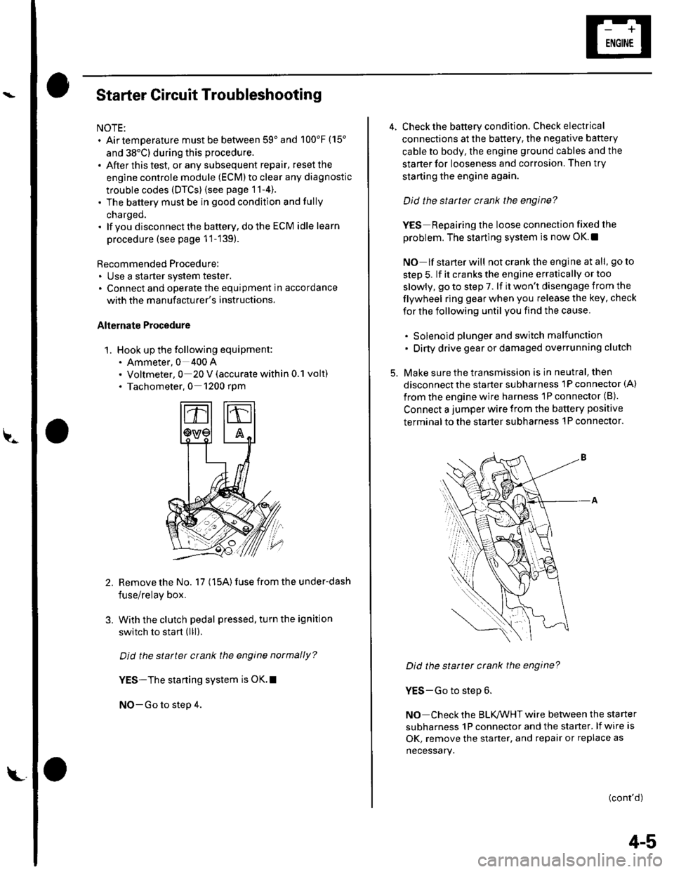
Recommended Procedure:. Use a starter system tester.. Connect and operate the equipment in accordance
with the manuf acturer's instructions.
Alternate Procedure
1. Hook up the following equipment:. Ammeter, 0 400 A. Voltmeter, 0 20 V (accurate within 0.1 volt). Tachometer,0 1200 rpm
2.Remove the No. 17 (15A) fuse from the under-dash
fuse/relay box.
With the clutch pedal pressed, turn the ignition
switch to start (lll).
Did the starter crank the engine normally?
YES-The starting system is OK.I
NO-Go to step 4.
3.
L
4-5
4. Check the battery condition. Check electrical
connections at the battery, the negative baftery
cable to body, the engine ground cables and the
starter for looseness and corrosion. Then try
starting the engine again.
Did the statter crank the engine?
YES Repairing the loose connection fixed the
problem. The starting system is now OK.!
NO lf starterwill notcranktheengine atall, goto
step 5. lf it cranks the engine erratically or too
slowly, go to step 7. lf it won't disengage from the
flywheel ring gear when you release the key, check
for the following until you find the cause.
. Solenoid plunger and switch malfunction. Dirty drive gear or damaged overrunning clutch
5. Make sure the transmission is in neutral, then
disconnect the starter subharness 1P connector (A)
from the engine wire harness 'lP connector (B).
Connect a jumper wire from the battery positive
terminal to the starter subharness 'l P connector.
Did the starter crank the engine?
YES-Go to step 6.
NO Check the BLK,ANHT wire between the starter
subharness 1P connector and the starter. lf wire is
OK, remove the starter, and repair or replace as
necessary.
(cont'd)
Page 41 of 1139

Starting System
Starter Circuit Troubleshooting
(cont'dl
6. Check the following items in the order listed untilyou find the open circuit.
. Check the BLIVWHT wire and connectors
between the under-dash fuse/relay box and theignition switch, and between the under-dash
fuse/relay box and the starter.. Check the ignition switch {see page 22-53).. Check the clutch interlock switch and connector.. Check the starter cut relay (see page 22-51).. Check LT GRN wire between the starter cut relayl
under-dash fuse/relay box and the clutch
interlock switch.. Check the BLK wire between the clutch interlock
switch and G501.
7, Check the cranking voltage and current draw.
ls ctanking voltage greatet than or equal to 8.7 V
and current draw less than or equal to 230 A?
YES-Go to step 8.
NO Replace the starter. or remove and
disassemble it, and check these items until you find
the cause.
. Starter armature dragging. Shorted armatu re winding. Excessive drag in engine
8. Check the engine speed while cranking the engine.
ls the engine speed above 100 tpm?
YES Go to step 9.
NO-Replace the starter, or remove and
disassemble it, and check for the following untilyou find the cause.
. Excessively worn starter brushes. Open circuit in commutator brushes. Open circuit in starter armature commutator
segments. Dirty or damaged helical splines or drive gear. Faulty drive gear clutch
9. Remove the starter, and inspect its drive gear andthe flywheel ring gear for damage. Replace anydamaged pans.I
4-6
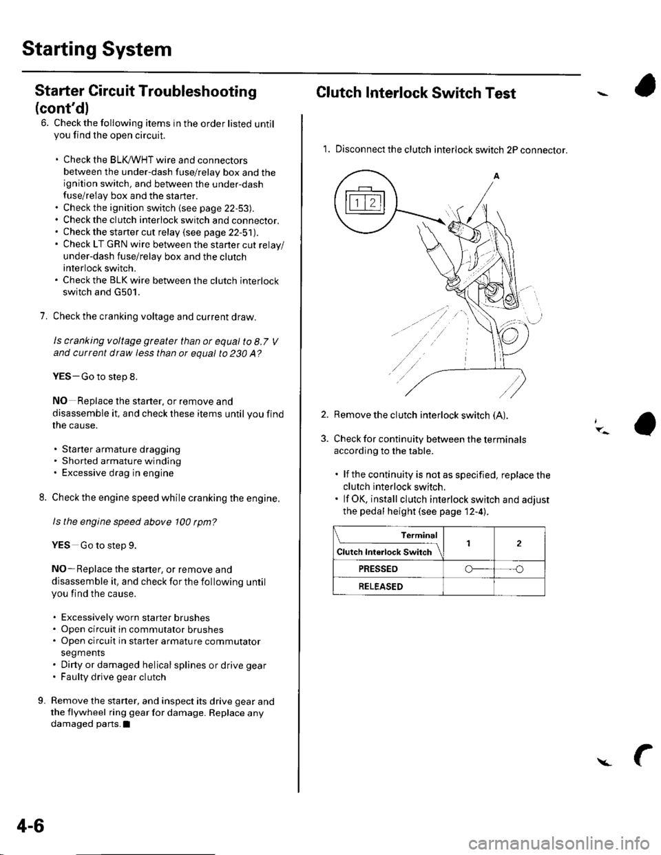
Clutch Interlock Switch Test
1. Disconnect the clutch interlock switch 2P connector.
2. Remove the clutch interlock switch (A).
Check for continuity between the terminals
according to the table.
. lf the continuity is not as specified, replace the
clutch interlock switch.. lf OK, install clutch interlock switch and adjust
the pedal height (see page 12-4l..
Terminal
Cl","f ri"t.tf ."tS""*Jrl2
PRESSEDo--- --o
RELEASED
Page 42 of 1139

et
Starter Solenoid Test
1. Disconnect the S and lvl connectors from the starter
solenoid.
2. Check the hold-in coil for continuity between the S
terminal and the armature housing (ground). There
should be continuity.
. lf there is continuity, goto step 3.. lf there is no continuity, replace the solenoid,
3. Check the pull-in coil for continuity betwee n the S
terminal and M terminal. There should be
continuity,
. lf there is continuity, the solenoid is OK.
. lf there is no continuity, replace the solenoid,
4-7