2003 HONDA CIVIC warning
[x] Cancel search: warningPage 2 of 1139

INTRODUCTION
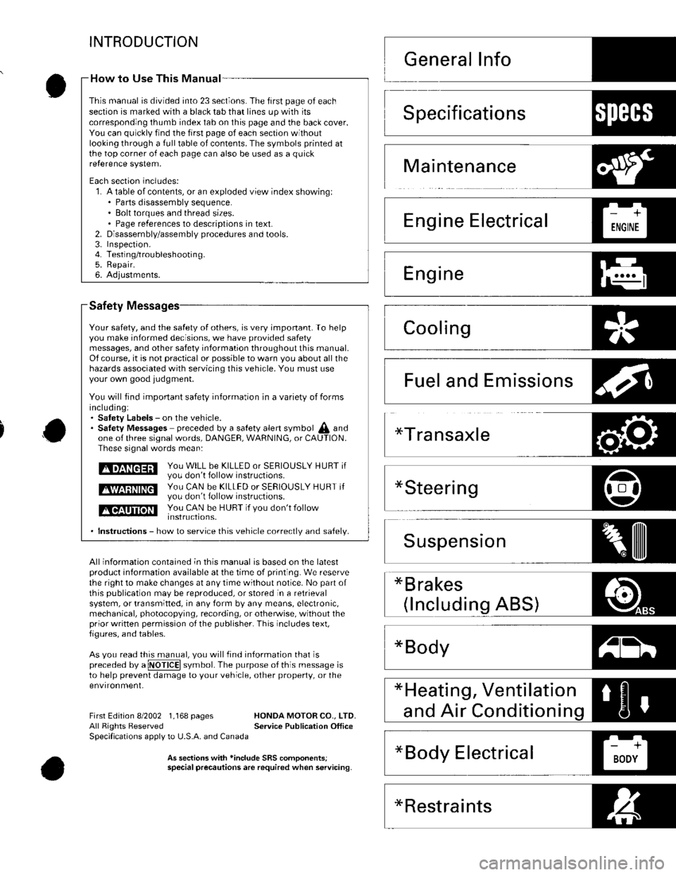
Safety
Your safety, and the satety of others, is very important. To helpyou make informed decisions, we have provided safetymessages, and other safety information throughout this manual.Of course, it is not practical or possible to warn you about all thehazards associated with servicing this vehicle. You must useyour own good judgment.
You will find impoftant safety information in a variety of formsincluding:. Satety Labels - on the vehicle.. Satetv Messages preceded by a salety alert symbol A andone of three signal words, DANGEF, WARNING, or CAUTION.These signal words mean:
tmEnEEril y;,: H,ll i": 5* i5"?;r s E R I o u s LY H u Br ir
E$EEEE ys,: f#,ff ,:hl:3,:JjERrousLY HURT ir
tlGtltT]llilll You cAN b€ HUBT if vou don't follow
. lnstructions - how to service this vehicle correctlv and safelv.
All information contained in this manual is based on the latestproduct information available at the time of printing. We reservethe right to make changes at any time without notice. No part ofthis Oublication maV be reDrodLrced, or stored in a retrievalsystem, or transmitted, in any form by any means, electronic,mechanical, photocopying, recording, or otherwise, without theprior written permission o{ the publisher. This includes text,figures, and tables-
As vou read this manual, vou will tind information that ispreceded by a @ symbol. The purpose of this message isto help prevent damage to your vehicle, other property, or theenvironment,
*Bodyz-tl!^t l
First Edition 8/2002 1,168 pages HONDA MOTOR CO.. LTD.All Rights Reserved Service Publication OfficeSpecifications apply to U.S.A. and Canada
As seclion3 with *inclode SRS comoonentsispecial precautionsare required when servicing.
How to Use This Manual -
This manual is divided into 23 sections. The first page of eachseclion is marked with a black tab that lines up with itscorresponding thumb index tab on this page and the back cover.You can quickly find the first page of each section withoutlooking through a full table of contents. The symbols printed atthe top corner of each page can also be used as a quickre{erence system.
Each section includes:1. A table of contents, or an exploded view index showingl. Parts disassembly sequence.. Bolt torques and thread sizes.. Page references to descriptions in text.Disassembly/assembly procedures and tools.Inspefiron.Testing/troubleshootin g.Repair.Adjustments.
2.3.4.5.6.
Specifications1)ll:{l+'
Maintenance
Emissions
*Restraints
Page 3 of 1139

)
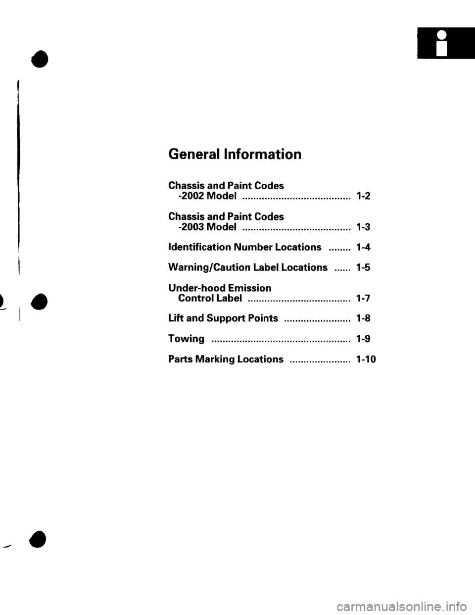
General Information
Ghassis and Paint Codes
-2002 Model ................. 1-2
Chassis and Paint Codes
-2003 Model ................. 1-3
ldentification Number Locations ........ 1-4
Warning/Caution Label Locations ...... 1-5
Under-hood Emission
Control Label ........... .... 1-7
Lift and Support Points .........,....,.......,. 1-8
Towing ...... 1-9
Pafts Marking Locations ...................... 1-10
Page 7 of 1139

!
..r'
, I O warning/cautionLabelLocations
NOTE: FRONT PASSENGER AIRBAG WARNING TAG(CHILD SEAT) is installed on the glove box on the U.S.
mooet.
Passenger's Compartment:
SRS INFORMATIONU.S. model
SRS WARNINGINFORMATION
FRONT PASSENGERMODULE DANGER
MONITORNOTICE
SIDE AIRBAG CAUTIONLocated on driver'sano passen9er sdoorjamb (not shown)
SIDE MODULEDANGER
,/
FRONTSEATBELTTENSIONERCAUTION
Steering Wheel:
DRIVER MODULEDANGER
CABLE REELCAUTION
(cont'd)
1-5
Page 8 of 1139

General Information
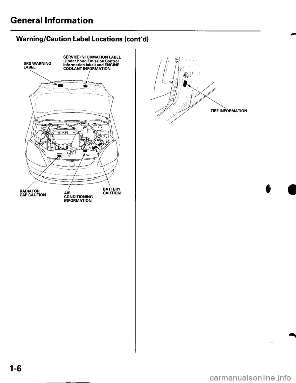
Warning/Caution Label Locations (cont'dl
SRS WARNINGLABEL
SERVICE INFORMATION LABEL(Undor-hood Emission ControlInformation lab€l) and ENGINECOOLANT INFORMATION
RADIATORCAP CAUTION
BATTERYCAUTION
1-6
t
TIRE INFORMATION
c
Page 715 of 1139

Shift Lever Trim Removal/lnstallation
NOTE:. Take care not to scratch the dashboard and related
pa rts.. Put on gloves to protect your hands.
1. Remove the glove box (see page 20-63).
2. Remove the shift knob.
Using a ratchet wrench and an 11 inch extension(A) wrapped with a shop towel (B), carefully insert
the extension through the glove box opening, andpush the shift lever trim (C) from under the trim to
release the clips (D) and hooks (E) of the left side.
Fastener
D>clip,
i:F\V
Locations
2 E >Hook,2
.-a7
-t1
u
4. Pull outthe shift levertrim (A) by hand to release
the remaining cllps (8, C) and hooks (D), and
disconnect the hazard warning switch connector (El,
then remove the trim.
Fastener Locations
B >:Clip, 1C>: Cl;p, 1 D>: Hook,3
,,.;w,
Install the trim in the reverse order of removal, and
note these rtems.
. Make sure the hazard warning switch connectot
is plugged in properly.. Push the clip and hook portions into place
securely,
-
,,
20-61
Page 831 of 1139

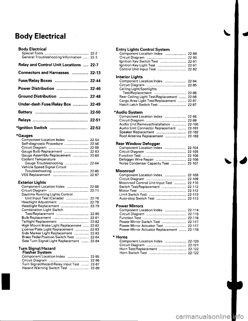
\Body Electrical
Body ElectricalSpecialToolsGeneral Troubleshooting tntorrnaiion.'......
Relay and Control Unit Locations .....
Connectors and Harnesses
Fuse/Relay Boxes ...............................
Power Distribution .............................
Ground Distribution ...........................
Under-dash Fuse/Relay Box ..............
Battery ..............
Relays ................
*lgnition Switch ..............
*Gauges
Component Location Index .......................Self-diagnostic Procedure ..........................Circuit DiagramGauge Bulb Replacement ..........................Gauge Assembly ReplacementCoolant Temperature
Gauge Troubleshooting .... ....................Vehicle Speed Signal CircuitTroubleshootingVSS Replacement
Exterior LightsComponent Location Index .......................Circuit DiagramDaytime Running Lights ControiUnit Input Test (Canada) ........................Headlight Ad,ustment .................. .. .....Headlighr Replacement ..............................Combination Light SwitchTest/ReplacementBulb ReplacementTaillight Replacement ..........................High Mount Brake Light Replacement ......License Plate Light Replacement ..............Side Marker Light Replacement ................Brake Pedal Position Switch Test ..............Side Turn Signal Light Replacement ........
Turn Signal/HazardFlasher SystemComponent Location Index .......................Circuit DiagramTurn Signal/Hazard Relay lnputTest ........Hazard Warning Switch Test
22,3
22-7
22-13
22-44
22-46
22-4A
22-49
22-50
22-51
22-53
22-5422-5622-5422 6322-64
22-64
22-6522 61
22-6822--71
22-7 622-7422-79
22-AO22-4122-8222-4222-4322-4322-4422-84
22-8�522 A622-8722-88
22-10422-105
22-10622-107
Entry Lights control systemComponent Location Index ....................... 22-89Circuit Diagram ......... 22 90lgnition Key Switch Test .....................,...... 22-9'llgnition Key Light Test ............................... 22-91Control Unit Input Test ..........,.................... 22 92
Interior LightsComponent Location Index ....................... 22-94Circuit Diagram ......... 22-95Ceiling LighVSpotlightsTesVReplacement ................................... 22-96Rear Ceiling Light TesVReplacem ent ........ 22-96Cargo Area Light Test/Replacem ent ......... 22-97Hatch Latch Switch Test ..,..,....................... 22-97
*Audio SystemComponent Location Index ....................... 22-98Circuit Diagram ......... 22,99Audio Unit Removal/lnstallation ............... 22-1OOAudio Unit Connector Replacement ......... 22-101Speaker Replacement ................................ 22-102Roof Antenna Rep1acement ....................-.. 22-103
Rear Window DefoggerComponent Location Index ...........Circuit Diasram .. ....... .. ..... ....... ...:::::.::.::.Function TestDefogger Wire Repair .................................Noise Condenser CapacityTest ................
MoonroofComponent Location Index ....................... 22-1OBCircuit Diagram ......... 22-109Moonroof Control Unit Input Test ............. 22-'l10Switch TesVReplacement ........,.....,........... 22-1 12Motor Test ................. 22-112Limit Swilch Test ...... 22-'l'13Auto-stop Switch Test ................................ 22-1 13
Power MirrorsComponent Location Index ....................... 22-114Circuit Diagram ......... 22-115Function Test ............. 22-116Power Mirror Switch Test .......................... 22-ll7Power Mirror Actuator Test ....................... 22-117Power Mirror Actuator Replacement ........ 22-11A
* HornsComponent Location Index ....................... 22-120Circuit Diagram ......... 22-121Horn TesVReplacement ...........................-. 22-122Horn Switch Test .,.... 22-122
\
Page 857 of 1139

Connectors and Harnesses
Dashboard Wire Harness A {Left branchl
Connector or TerminalffiAccessory power socketAudio antennaBrake pedal position switchClutch interlock switchClutch pedal poistion switchCruise control unitCruise main switchDaytime r!nning lights control unitDaytime running lights relayGauge assembly connector AGauge assembly connector BHazard warning switchHeater control panel connector AHeater control panel connector BHVAC push switch assemblyKeyless receiver unitLow beam cut relayOptional security connectorPower mirror switchUnder-dash fuse/relay boxconnector K (see page 22-45)Under'dash fuse/relay box
L {see page 22-45}Underdash fuse/relay boxconnector M lsee page 22'45)Under-dash fuse/relay boxconnector N (see page 22-45)UndeFdash fuse/relay boxconnector O (see page 22-45)UndeFdash fuse/relay boxconnectorY (see page 22 45)c504
c505
c506
c507
c508
c509
c510
22226
3029628
I820111819105327
,I4
12
11
34
1
24
25
2 Under middle of dash2 Under left side of dash4 ] Under left side of dash2 ] Under left srde of dash2 | Under left side of dash14 I Under left side of dash5 Under left side of dash14 Under lett side of dash4 Under lett side of dash22 I Behind gauge assembly22 i Behind gauge assembly10 Behind hazard warnning switch22 Behind heater control panel'14 Behind heater control panel10 ] Behind HVAC switch assembly5 I Under middle of dash5 lUnderleftsideofdash16 Under lefr side of dash13 Under left side oI dash17 ln the under-dash fuse/relay box
CanadaCanada
l0In the under-dash fuse/relay box
In the undeFdash fuse/relay box
In the underdash fuse/relay box
In the under-dash fuse/relay box
In the under-dash fuse/relay box
Under left side of dash
Under left side ot dash
Under left side of dash
Under left side of dash
Under middle of dash
Under middle of dash
Under middle ol dash
Driver's door wire harness(see page 22'40)Driver's door wire harness(see page 22-40)Left side turo signal lightsuonarnessRoof wire harness (see page22 3AlFloor wire harness {see page22-341Floor wire harness (see page22 34JDashboard wire harness B(see oaoe 22-30)
12
12
G501
G503
1
21
Under gauge assembly
Under left side of dash
Body ground via dashboard
Body ground via dashboard
Left Side Turn Signal Light Sub harness
Connector to Harness Index (cont'd)
L
Connector or TerminalCavitiesLocationConnects toNolesLeft side turn signal lightc506353422Behind left side turn signal lightUnder left side of dashDashboard wire harness A
22-26
Page 916 of 1139

Turn Signal/Hazard Flasher
Component Location Index
COMBINATION LIGHT/TURN SIGNAL SWITCHTest, page 22-80Beplacement, page 22-80
TURN SIGNAL INDICATOR LIGHTS(ln the gauge assembly)Bulb Replacement, page 22'63
HAZARD WARNING SWITCHTest, page 22-88Replacement, page 22-88
TURN SIGNAL/HAZARD RELAYInput Test, page 22-87
UNDER.DASH FUSE/RELAY BOX
22-85