2003 HONDA CIVIC warning
[x] Cancel search: warningPage 918 of 1139

Turn Signal/Hazard Relay Input Test
1. Removetheturn signal/hazard relay (A) from the under-dash fuse/relay box (B).
Inspect the relay and fuse/relay box socket terminals to be sure they are all making good contact
. lf the terminals are bent. loose, or corroded, repairthem as necessary, and recheckthe system.
. lf the terminals look OK, go to step 3.
Make these input tests at the fuse/relay box.
.lfanvtestindicatesaproblem,findandcorrectthecause,thenrecheckthesystem.
. lf all the inputtests prove OK,theturn signal/hazard relay must befaulty. Replace it
000i 0!1000
00u! u0
CavitvTesl conditionTest: Desired resultPossible cause il result is not obtained
1Under all conditionsCheck for continuity to ground:
There should be continuiw.
. Poor ground (G201)
. An ooen in the wire
3lgnition switch ON ( ll)
Hazard warning switch
OFF
Check for voltage to ground:
There should be battery voltage.
' Blown No. 19 (7.5A) fuse in the
under-dash fuse/relay box. Faulty hazard warning switch. An ooen in the wire
Hazard warning switch
ON
lgnition switch OFF
Check for voltage to ground:
There should be battery voltage.
. Blown No. 5 {10A) fuse in the
under-hood fuse/relay box. Faulty hazard warning switch. An ooen in the wire
2lgnition switch ON ( ll)
and turn signal switch
in Right or Left position
Connect No. 2 terminalto No. 3
terminal:
Right or left turn signal lights
should come on.
. Poor ground (G201, G301, G501,
G502, G553). Faulty turn signal switch. An oDen in the wire
lgnition switch OFF
Hazard warning switch
ON
Connect No.2 terminal to No. 3
termrnal:
Hazard wa rning lights should
come on.
. Poor ground (G201, G301, G501,
G502, G553). Faulty hazard warning switch. An open in lhe wire
22-87
Page 919 of 1139

Turn Signal/Hazard Flasher
1.
2.
Hazard Warning Switch Test
Remove the center panel (see page 20-62).
Disconnect the 10P connector (A) from the hazard
warning switch (B).
4.
Push out the hazard warning switch from behind
the center panel (C).
Check for continuity between the terminals in each
switch position according to the table.
lf the continuity is not as specified, replace the bulb(D) orthe hazard warning switch.
Termin6l
;;;-_-\124710
OFF
ON@
3.
22-88
Page 1136 of 1139

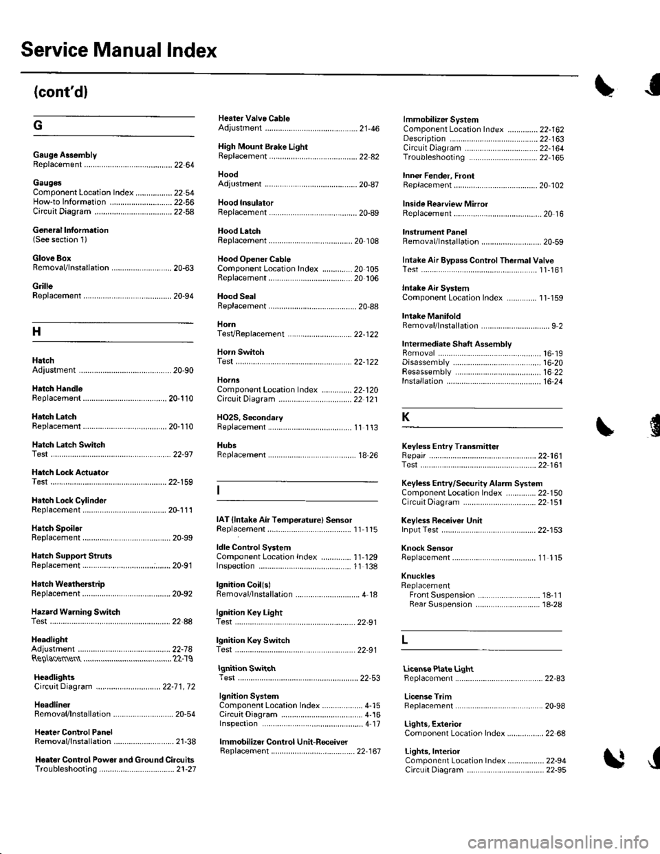
Service Manual Index
(cont'dl
Gauge A3semblyReplacement......................................... 22 64
Gaug€sComponent Location Index ..........-...... 22 54How-to lnformation ........................22-56Circuit Diagram22-54
Heater Valve CableAdjustment ...................... .................... ?1-46
High Mount Brake Light8ep|acement......................................... 22 82
Hood
lmmobilizer SystemComponent Location In dex .............. 22-162
\
G
Description
Genoral Information(See seclion 1)
Glove BoxRemoval/1nsta11ation .......................-.... 20-63
GrilleReplacement...........-............................. 20-94
Hood lnsulatorReplacement......................................... 20-89
Hood LatchRep1acement................... ..........20 108
Hood Opener CableComponentLocation Index ..............20 105Replacement ................ . . ........... .....20 106
Hood SealBeplacement.-...........................-........... 20-88
HornTesVReplacement . . ................ ...... 22-122
CircuitDiagram ...........................22-164Troubleshooting ............................ 22,165
Inner Fender, FronlRepf acemenl....................................... 20-102
Inside Rearview MirrorReplacement..........-.............................. 20 16
Instrument PanelRemoval/1nsta11ation................. ....... 20-59
Intake Air Bypass ControlThermal ValveTesr................................ ..... ..11-161
Intake Air SystemComponent Location Index ...-.-........ 11-159
Intake ManitoldRemoval/1nsta11ation ................................ I 2
lntermediate Shaft AssemblyRemova1 ................-.-...-......................... 16-19Disassemb|y................... ... ......-.... 16,20Resassemb|y ........................................ 16 22Installation .........-...-.............................. 16-24
Keyless Entry Transmitter
Adjuslment
H
Adiustment .......
Hatch Handle
Horn SwitchTest ............-........
HornsComponent Location IndexCirc!it Diagram
H02S. SecondaryReplacement
..............22-120Replacement
22-122
22 12120-110
20-'110Hatch LatchReplacement$
K
Hatch Latch Switch
.... 11 113
HubsReplacement. ... .................................. 1A 26Test
Test
Replacement
Hatch Support StrutsBeplacement.....
Hatch WeatherstrioReplacement....
Hazard Warning Switchtest
ldle ControlSystemComponentLocation Index .............. 11-129Inspection,.,.........-.......,.,.,,,,,,.,,,.,.,..... 1'l 138
lgnition CoillslBemoval/lnstallation ...............-.............. 4 18
22-161Test ...................................................... 22 161
Keyless Entry/Security Alarm SystemComponenl Location Index .............. 22 150Circuil Diagram ................. . .............. 22 151
Keyless Receiver Unitlnput Test ............................................ 22-153
Knock SensorReplacement......-................................ 1 1 115
KnucklesReplacementFront Suspensron ............................. 18-1 1Rear Suspension ........ .................-... 18-28
Repair ...............
H.tch Lock Actuator22-159
Hatch Lock CylinderRep|acement....................................... 20,111
Hatch SpoilerIAT {lntake Air Temperature} SensorReplacement.,.........-...'11 115
20-91
20-92
.................... 22_88lgnition Key LightTest,,.,,,,.,...,......-.
H6adlightAdjustmentlgnition Key Switch
....................... 22-91
....................... 22-91..22-78TestReQ\ace$entlgnition SwitchTest .,,,.,.,.,,,,.,.,.......22-53License Plate LightReplacement...........-... - ... .....22-83
License TrimReplacement..................-...-..........-....... 20-98
Lights, ExteriorComponent Localion Index.................22 68
Lights,InteriorComponent Location Index................. 22-94CircuitDiagram .. .. ...... .... 22-95
HcadlightsCircuit Diagram .............................. 22-71, 72
HeadlinerRemoval/lnstallalion ............................ 20-54
Heater ControlPanelRemoval/1nsta11ation ............................ 21-38
Heater Control Power and Ground CircuitsTroubfeshooting......... .......................21-27
lgnition SystemComponent Location Index ................... 4-15CircuitDia9ram .................................... 4'161nspection ............................................... 4-17
lmmobilizer Control Unit-Receiver
J
22-161
Page 1139 of 1139

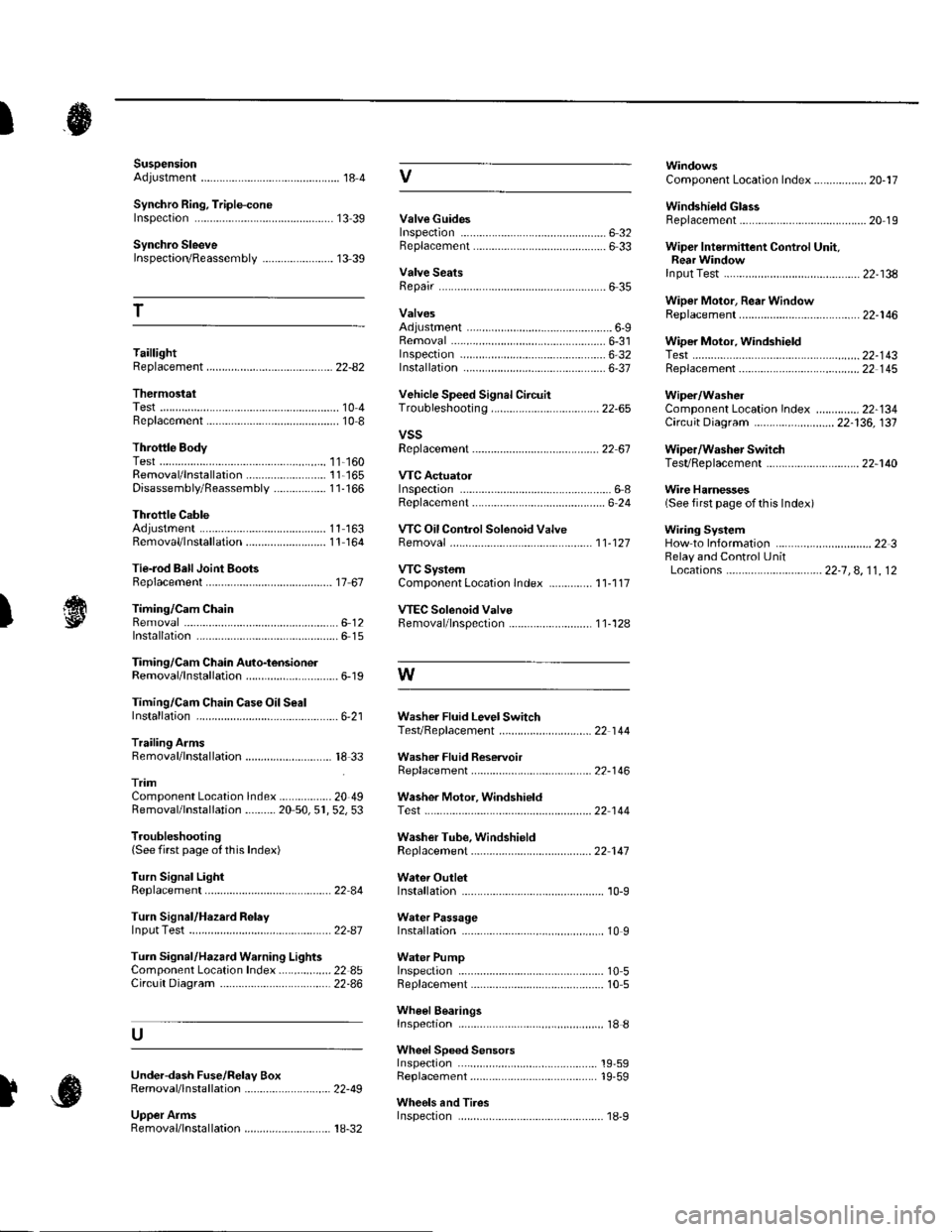
SuspensionAdjustment................-............................184 VComponent Location Index................. 20-17
Windshield GlessReplacement............-..............-............. 20 19
Synchro Ring, Triple-coneInspection...............-..........................1339 ValveGuides
Synchro SleeveInspectaon/Reassemb1y ....................... 13 39
Inspection ............-.-................................ 6 32Beplacement ..........-................................ 6 33 Wiper Intermittent Control Unit,Rear WindowInput Test
T
Valve SeatsRepair ...................................................... 6 35.....22-134
WiDer Motor, Rear WindowRep1acement....................................... 22-1 46Adjustment .-.-.......Removal ...-...-......................................-... 6-31 WiDer Motor, windshield6-9
.....6-32 Test.......-..........-.....-.............................22-143Taillight
ThermostaiTest ........................
Inspec!on
Vehicle Speed Signal Circuit
VTC System
Wiper/WasheI
Wi.ing System
10 4 Troubleshooting .....-... ..........................22-65 Component Location In dex ..............22-134Replacement.....-...-....... ...................... 10 IvssThrottle BodyTest ..................Removal/lnstallation .. . . . . . .. ... 11-'165 VTC ActuatorDisassembly/Feassemb|y................-11-166 Inspection
Circuit Diagram .......................... 22-136, 131
Replacement -.............. ............ .............22 61 Wiper/Washor SwitchTesVReplacement .............................. 22-1 40
.................68 WireHarnesses
11-160
Replacement ........................................... 6 24 (Seefirstpageofthislndex)Throttle CableAdjustment ...... ...-.................... 11163 VTC Oil ConlrolSolenoid ValveRemoval/1nsta11ation..........................11164 Removal....-...-... |1-127 HowtoIn{ormation ...............................223Belay and Control UnitLocations .-....-.............. -.-.-....- 22-7, 4, 1 1, 12Beplacement.........-............................... 1767 ComponentLocationlndex.............. 11-117Tie-rod Ball Joint Boots
lnstallation
Replacement
Turn Signal/Hazard Relay
tsTiming/Cam ChainVTEC Solenoid Valve...612 Femoval/lnspection....-......................11-128................ 6 15
Timing/Cam Chain Auto-tensionelRemoval/1nsta11ation..............................6-19 W
Troubleshooting{See first page ot this Index)
Turn Signal Light
Timing/Cam Chain CaseOil SealInstallation......................-......................6,21 Washer Fluid Level SwitchTesVReplacement .............................. 22 1 44Trailing ArmsRemoval/lnstallation .............. . . . . ..... 18 33 Washer Fluid ReservoirReplacement ....................................... 22-1 46tnmComponent Location lndex ................- 20 49 Washer Motor, WindshieldRemoval/lnstallation ..-.......20 50,51,52,53 Test -..............-.............. ........................22 144
Washer Tube, WindshieldReplacement......-...-............................ 22 1 47
W.ter Outlet.........22 A4 Installation ..................-........................... '10-9
InputTest........22-87 lnstallation................ 10IWeter Passage
Wheels andTires
Turn Signal/Hazard Warning Lights Water PumpComponent Location In dex .................22 85 Inspection ........................... .. . . . ....... 10 5Circu it Diagram ................-................... 22-86 Replacement .-......................................... 10 5
U
WheelBearingsInspec|ion ....................................... ....... 18 8
Wheel Speed SensorsInspection ..-..,.,.,,.,,,,,.,.,,,...................... 19-59Replac€ment ........-....... . . . . . . .. -.... 19-59UndeFdash Fuse/R€lay BoxRemoval/lnstaf lation ............................ 22-49
Upper ArmsRemoval/|nsta11ation................. ... 18-32
],sInspect|on