Page 14 of 1139

ne
ItemMeasurementOualificationStandard or New Service Limitlgnition coilRated voltage
Firing order12V
1 3-4 2
NGK: tZFB6K11
DENSO: SKJ20DR-M11
1.0 1.1mm(0.039 0.043 in.) 1.3mm(O.OS1 in.)
Spark plugType
Gap
lgnition timingAt idle (check rhein neutral: 8t2' ETDC at 650150 rpm
AlternatorOutputAt 13.5 V and
normalengine
temperature
80A
2.2 3.0 ACoil lrotor) resistanceAt 68.F (20'C)
5|lp flng u.u.14.4 mm {0_57 in.) 14.0 mm (0.55 in.)Brush length10.5 mm (0.41 in.l 1.5 mm {0.06 in.)Brush spring tension2.9 3.5 N (0.30 0.36 kgf,0.7-0.8 tbs)StarterOutput
Commutator mica depth0.50 0.80 mm (0.020-0.031 in.) 0.20 mm 1O.OO8 in.)Commutator tunouto:BlalqryL4i) max o.o5 mm (0.002 in.)Commutator O.D.28.0 mm (1.10 in.) 27.0 mm (1.06 in.)Brush length14.0 14.5 mm {0.55 0.57 in.) 9.0 mm {0.35 in.)
(
I
Standards and Service Limits
Enqine Electrical
E
e_a
.l
nqtne
ItemMeasurementOualificationStandard or NewService LimitCompressionPressure check at 250 rpm with wide
open throftle. (See Design Specs for
rato,
Minimum930 kPa (9.5 kgflcmr, 135 psi)
Maximum
vanatton
200 kPa {2.0 kgf/cm',28 psi)
2-2
Page 24 of 1139

cont'
ItemMeasuremeniOualificationSpecilicationSTEERINGTypeElectric, Power assisted rack and pinion
Overall ratio15.1Turns,lock to-lock
Steering wheel diameter360 mm (14.2 in)SUSPENSIONTypeIndependent srrul with stabiliTer. coil springRearDouble wishboneShock absorberFrontTelescopic, hydraulic. nitrogen gas-frlled
RearTelescopic, hydraulic, nitrogen gas,filledWHEEL
ALIGNMENT
CamberFront0"00'
Bear0.45'�
CasterFront1'33'�TotaltoeFront0 mm (0 in.)
RearIn 2 mm (1/16 in.)BRAKESType of service brakeFrontPowerassisted self-adjusling ventilated disc
BearPower-assisted self-adjusting solid discType of parking brakeMechanical actuating, rear wheelsPad friction surface areaFront45 cm'(7.0 sq in.)x2
Rear28 cm'(4.3 sq in.) x 2TIRESSize offront and reartiresPl95/60 815 88VSize o{ spare tireT125r0 D15 95MAIR
CONDITIONING
CompressorTypeScroll
Number of
cylinders
Capacity85.7 m015.23 cu in.)/rev.
Maximum speed12,000 rpm
Lubricant capacity130 m0 {4 1/3 floz)
LubricanttypeSP-10 (P/N 38897'P13-A01AH or38899-P13 A01)CondenserTypeCorrugated finEvaporatorTvpeCorrugated fin
BlowerTypeSirocco fan
Motor type220 Wl12 V
Speed control4 Speeo
Maximum capacity480 m" 116.900 cu ft)/hTemperature controlAirmixtype
Compressor clutchTvpeDry, single plate, poly-V belt drive
Electricalpower
cons!mptron at
68"F (20.C)
42 W maximum at 12 V
RefrigerantTypeHFC 134a (R-134a)
Capacity500 550 g (17.6 19.4 oz)
Design Specifications
C
aL
2-12
../ a
Page 25 of 1139
t
v
2-13
o
o
a
ItemMeasurementOualilicationSpecitication
ELECTRICAL
RATINGS
Battery12V 36 AH/5 hours
Sta rter12 V-.1.1 kW, 1.2 kW
Alternator12V 95A,90A
FusesUnder-hood fuse80 A, 60 A, 50 A, 40 A, 30 A, 20 A, 15 A, 10 A, 7.5 A
Under'dash Iuse30 4,20 a, 15 A, 10 A,7.5 A
Light bulbsHeadlight high
beam
'12 v.' 60 w
Headlight low
beam
12V 55W
Frontturn signal
liqhts
12V 21W
Front parlinq lights12V 5W
Bear turn signal
lights
12V " 21W
FronVrear side
marker lights
12V 5W
Brale/taillighls12V 21/5W
High moLrnt brake
light
12V 5W
Back up lights12V 21W
License plate light12V 5W
Ceiling light'12 v'.8 w
Cargo area light12V 5W
Spotlights12V 5W
Gauge lights
Indicator lightsLED
Side turn signal
light
12V 5W
Page 36 of 1139

\.
Engine Electrical
Engine Electrical
SpecialTools
Starting System
Comoonent Location Index ...............
Circuit Diagram
Starter Circu it Troubleshooting
Clutch Interlock Switch Test
Starter Solenoid Test ..............
Sta rter Performance Test
Starter Reolacement ...............
Starter Overhaul .......................
lgnition System
Component Location Index ...............
Circuit Diagram
lgnition Timing Inspection
lgnition Coil Removal/1nsta11ation .......................
Spark Plug Inspection
Charging System
Component Location Index .................................. 4-2O
Circuit Diagram ........................... 4-21
Charging Circuit Troubleshooting ....................... 4-22
Drive Belt Inspection ................... 4-26
Drive Beft Replacement .............. 4-26
Drive BeftAuto-tensioner Inspection .................. 4-27
Drive Beft Auto-tensioner Replacement .............. 4-28
Alternator Reolacement ............. 4-29
Alternator Overhaul ................ .... 4-30
Cruise Control
Component Location Index .................................. 4-36
Circuit Diagram ........................... 4-37
Symptom Troubleshooting Index ....................... 4-38
Cruise Control Unit lnDut Test ............................. 4-40
Main Switch TesVReolacement ........................... 4-42
SeVResume/Cancel Switch TesVReplacement .. 4-42
Cruise Control Actuator Test ...... 4-43
Cruise Control Actuator/Cable Replacement ...... 4-44
Actuator Cable Adjustment .................................. 4-45
Clutch Pedal Position Switch Test ....................... 4-45
4-2
4-J
4-4
4-5
4-6
4-7
4-8
4-9
4-10
4-15
4-16
4-17
4-18
4- 19
-+
ENGINE
Page 37 of 1139
Engine Electrical
SpecialTools
I
NumberTool NumberDescriptionotv
o
@
07746-0010400
07749-0010000
Attachment, 52 x 55 mm
Driver
1
1
\C
4-2
(a
Page 40 of 1139

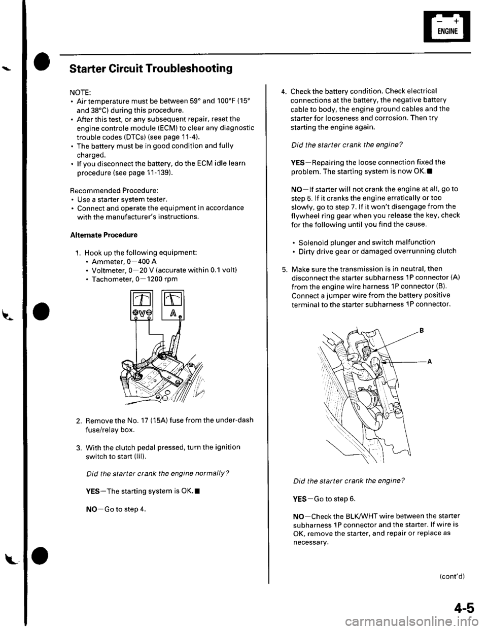
Starter Circuit Troubleshooting
NOTE:. Airtemperature must be between 59'and 100'F (15'
and 38'C) during this procedure.
. After this test, or any subsequent repair, reset the
engine controle module (ECM) to clear any diagnostlc
trouble codes (DTCS) {see page 11-4).. The battery must be in good condition and fully
charged.. lf you disconnect the baftery, do the ECM idle learn
procedure (see page 11-139).
Recommended Procedure:. Use a starter system tester.. Connect and operate the equipment in accordance
with the manuf acturer's instructions.
Alternate Procedure
1. Hook up the following equipment:. Ammeter, 0 400 A. Voltmeter, 0 20 V (accurate within 0.1 volt). Tachometer,0 1200 rpm
2.Remove the No. 17 (15A) fuse from the under-dash
fuse/relay box.
With the clutch pedal pressed, turn the ignition
switch to start (lll).
Did the starter crank the engine normally?
YES-The starting system is OK.I
NO-Go to step 4.
3.
L
4-5
4. Check the battery condition. Check electrical
connections at the battery, the negative baftery
cable to body, the engine ground cables and the
starter for looseness and corrosion. Then try
starting the engine again.
Did the statter crank the engine?
YES Repairing the loose connection fixed the
problem. The starting system is now OK.!
NO lf starterwill notcranktheengine atall, goto
step 5. lf it cranks the engine erratically or too
slowly, go to step 7. lf it won't disengage from the
flywheel ring gear when you release the key, check
for the following until you find the cause.
. Solenoid plunger and switch malfunction. Dirty drive gear or damaged overrunning clutch
5. Make sure the transmission is in neutral, then
disconnect the starter subharness 1P connector (A)
from the engine wire harness 'lP connector (B).
Connect a jumper wire from the battery positive
terminal to the starter subharness 'l P connector.
Did the starter crank the engine?
YES-Go to step 6.
NO Check the BLK,ANHT wire between the starter
subharness 1P connector and the starter. lf wire is
OK, remove the starter, and repair or replace as
necessary.
(cont'd)
Page 59 of 1139

Gharging System
Charging Circuit Troubleshooting (cont'd)
6. Start the engine. Hold the engine at 3,000 rpm with
no load (in Neutral) until the radiator fan comes on,
then let it idle.
7. Raise the engine speed to 2,000 rpm, and hold it
there.
8. Turn the headlights (high beam) on, and measure
voltage at the under-hood fuse/relay box terminal.
ls the voltage between 13.9 and 15.1 v?
YES-Go to step 9.
NO Repair or replace the alternator components
(see page 4-30).1
9. Read the amperage at '13.5 V.
NOTE: Adjust the voltage by turning the blower
motor, rear window defogger, brake lights. etc. ON.
ls the amperage 604 ot morc?
YES-Alternator/regulator operation is OK. I
NO Repair or replace the alternator components(see page 4-30).1
4-24
\,
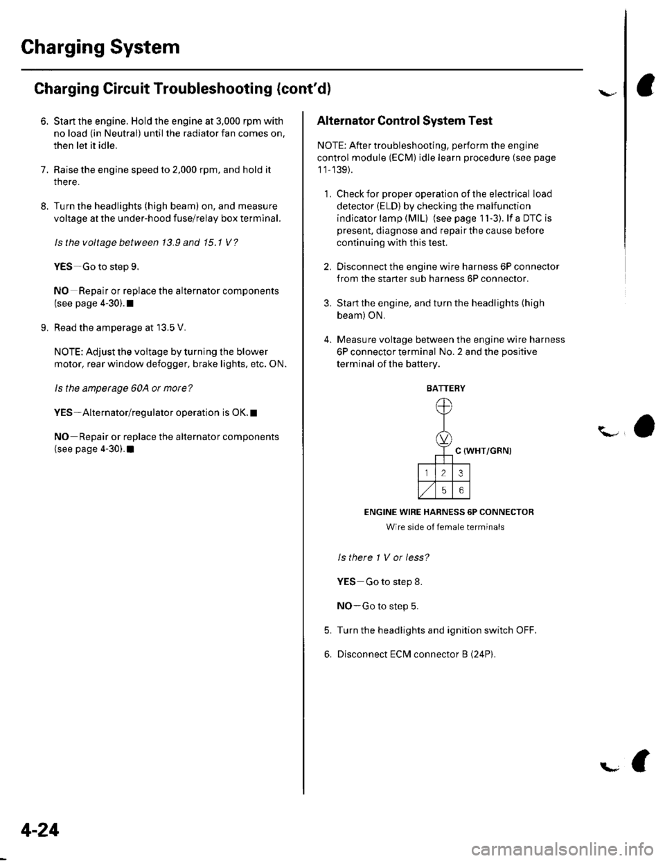
Alternator Control System Test
NOTE: After troubleshooting, perform the engine
control module (ECM) idle learn procedure (see page
11-139).
1 . Check for proper operation of the electrical load
detector (ELD) by checking the malfunction
indicator lamp (MlL) (see page 1 l-3). lf a DTC is
present, diagnose and repair the cause before
continuing with this test.
2. Disconnect the engine wire harness 6P connector
from the starter sub harness 6P connector.
3. Start the engine, and turn the headlights (high
beam) ON,
4. Measure voltage between the engine wire harness
6P connector terminal No. 2 and the positive
terminal of lhe battery.
C {WHT/GRN)
ENGINE WIRE HARNESS 6P CONNECTOR
Wire side of female terminals
ls there 1 V or less?
YES Go to step 8.
NO-Go to step 5.
Turn the headlights and ignition switch OFF.
Disconnect ECM connector B (24P).
5.
6.
BATTERY
Page 88 of 1139
Engine Assembly
Engine Removal (cont'd)
43. Use a marker to make alignment marks on the
reference lines (A) that align with the centers of the
rear subframe mounting bolts (B).
, !:_- _l.= :r -- ---.-','- -
44. Remove the front subframe (C).
5-8
ffi4
ffit'"
45. Disconnect the compressor clutch connector (A),
then remove the Ay'C compressor (B)without
disconnecting the A'./C hoses.
Check that the engine/transmission is completely
free of vacuum hoses, fuel and coolant hoses, and
electrical wiring.
Slowly lower the engine about 150 mm (6 in.).
Check once again that all hoses and wires are
disconnected trom the engine/transmission.
Lower the engine all the way. Remove the chain
hoist from the engine.
Remove the engine from under the vehicle.
46.
47.
48.
49.