2003 HONDA CIVIC Electrical
[x] Cancel search: ElectricalPage 836 of 1139

Testing and Repairs. Do not use wires or harnesses with broken insulation.
Replace them or repair them by wrapping the break
with electricaltape.. After installing parts, make sure that no wires are
oinched under them.. When using electricaltest equipment, followthe
manufacturer's instructions and those described in
this manual.. lf possible, insertthe probe of thetesterfromthe wire
side (except waterproof connector).
Use back Drobe adaotor 07TM-0010204.
Refer to the instructions in the Honda Terminal Kit for
identification and reolacement of connector terminals.
(cont d)
22-5
Page 837 of 1139

Body Electrical
General Troubleshooting Information (cont'dl
Five-step Troubleshooting
'1. Verify The Complaint
Turn on allthe components in the problem circuit
to verify the customer complaint. Note the
symptoms. Do not begin disassembly or testing
until you have narrowed down the problem area.
2. Analyze The Schematic
Look up the schematic for the problem circuit.
Determine how the circuit is supposed to work by
tracing the current paths from the power feed
through the circuit components to ground. lf
several circuits fail at the same time, the fuse or
ground is a Iikely cause.
Based on the symptoms and your understanding of
the circuit operation, identify one or more possible
causes of the problem.
3. lsolate The Problem By Testing The Circuit
Make circuit tests to check the diagnosis you made
in step 2. Keep in mind that a logical, simple
procedure is the key to efficient troubleshooting.
Test for the most likely cause of failure first, Try to
make tests at points that are easily accessible.
4. Fix The Problem
Once the specific problem is identified. make the
repair. Be sure to use proper tools and safe
proceoures.
5. Make Sure The Circuit Works
Turn on all components in the repaired circuit in all
modes to make sure you've fixed the entire
problem. lf the problem was a blown fuse, be sure
to test all of the circuits on the fuse. Make sure no
new problems turn up and the original problem
does not recur.
22-6
Wire Color Codes
The following abbreviations are used to identify wire
colors in the circuit schematics:
wHT....................,.,.............
YEL......................,,.......,......
B1K......................................
BLU ....,................................
GRN.....................................
RED ....................................,
oRN.....................................
PNK..........................,..........
BRN.....................................
GRY....................................,
PUR.....................................
1T81U..........................,.....
1TGRN...........................,...
White
Yellow
Black
Blue
Green
Red
Orange
Pink
Brown
Gray
Purple
Light Blue
Light Green
The wire insulation has one color or one color with
another color stripe. The second color is the stripe.
Page 1002 of 1139

ISystem Descriptions
The Multiplex Control System has four internal
functions:. Multiplexing (send multiple signals over sharedwtres). Wake up/sleep (runs at full power only on demand toreduce battery draw). Fail-safe (fixes or ignores faulty signals). Self-diagnosis (Mode 1 for the system, Mode 2 for
input lines)
The system controls the function of these circuits:. Entry lightcontrol (ignition key lightandceiting light). Wiper/washer intermittent wipe and park functions. Keyless/power door lock. Meter assembly, temperature gauge, and indicator
lights. HVAC (compressor and fan control). Key-in reminder. Headlight reminder. Seatbelt reminder
JI
/ar
22-171
Multiplex Communication
To reduce the number of wire harnesses, digital signals
are sent via shared multiplex communication linesrather than sending normal electrical signals throughindividual wires.. The input signals from each switch are converted todigital signals at the central processing unit (CpU).. The digital signalsaresentfromthetransmitting unitto the receiving unit as serial signals.. The transmitted signal is converted to a switch signalat the receiving unit, and it operates the related
component or monitors a swltch.. There are exclusive communicalion lines between
the ECM, the gauge assembly, and the under,dash
fuse/relay box.
Wake-up and Sleep
The multiplex control system has "wake-up" and"sleep" functions to decrease parasitic draw on the
battery when the ignition switch is OFF.. ln the sleep mode, the multiplex control unit stops
functioning (communication and CPU control) when it
is not necessary for the system to operate.. As soon as any operation is requested (for example, adoor is unlocked), the related control unit in the sleep
mode immediately wakes up and begins to function.. When the ignition switch is turned OFF, and the
driver's or front passenger's door is opened, then
closed, there is about a 10 second delay before the
control unit goes from the wake-up mode to the sleepmode.. lf any door is open, the sleep mode will not function.. lf a key is in the ignition switch, the sleep mode will
not function.. When in sleep mode, the draw is reduced from
70 80 mA to less than 10 mA.
Fail-safe
To prevent improper operation, the multiplex controlsystem has a fail-safe function. In the fail-safe mode,
the output signal js fixed when any part of the systemmalfunctions (for example a faulty control unit orcommunication line).
Each control unit has a hardware fail-safe function thatfixes the output signal when there is any CPUmalfunction, and a software fail-safe function thatignores the signal from the malfunctioning control unitand allows the system to operate normally.
Page 1021 of 1139

sRs
Precautions and Procedures
General Precautions
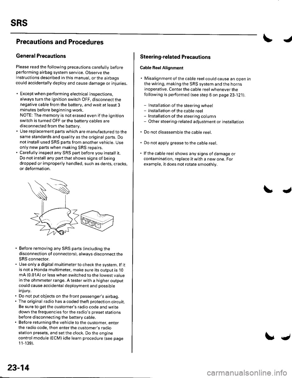
Please read the following precautions carefully beforeperforming airbag system service. Observe theinstructions described in this manual. or the airbags
could accidentally deploy and cause damage or injuries.
. Except when performing electrical inspections.
always turn the ignition switch OFF, disconnect the
negative cable from the battery, and wait at least 3minutes before beginning work.
NOTE: The memory is not erased even if the ignition
switch is turned OFF or the battery cables are
disconnected from the battery.. Use replacement pans which are manufactured to the
same standards and quality as the original parts. Do
not install used SRS parts from another vehicle. Useonly new pans when making SRS repairs.. Carefully inspect any SRS part before you install it.
Do not install any part that shows signs of being
dropped or improperly handled, such as dents, cracks,
or deformation.
. Before removing any SRS parts (including the
disconnection of connectors), always disconnect the
SRS connector.. Use only a digital multimeter to check the system. lf itis not a Honda multimeter, make sure its outout is 10mA (0.01A) or less when switched to the lowest value
in the ohmmeter range. A tester with a higher output
could cause accidental deployment and possible
injury.. Do not put objects on the front passenger's airbag.. The original radio has a coded theft protection circuit.
Be sure to get the customer's radio code and write
down the frequencies for the radio's preset stations
before disconnecting the battery cable.. Before returning the vehicle to the customer, enter
the radio code. then enter the customer's radio
station presets, and set the clock. Do the engine
control module (ECM) idle learn procedure (see page
11-139).
23-14
c
Steering-related Plecautions
Cable Reel Alignment
. Misalignment of the cable reel could cause an open in
the wiring, making the SRS system and the horns
inoperative. Center the cable reel whenever the
following is performed (see step 6 on page 23-121).
- Installation of the steering wheel- Installation of the cable reel- Installation ofthe steering column- Other steering-related adjustment or installation
. Do not disassemble the cable reel.
. Do not apply grease to the cable reel.
. lf the cable reel shows any signs of damage or
contamination. replace it with a new one. For
example, it does not rotate smoothly.
Page 1022 of 1139

Airbag Handling and Storage
Do not disassemble an airbag, lt has no serviceable
parts. Once an airbag has been deployed, it cannot be
repaired or reused.
For temporary storage of an airbag during service,
observe the following precautions.
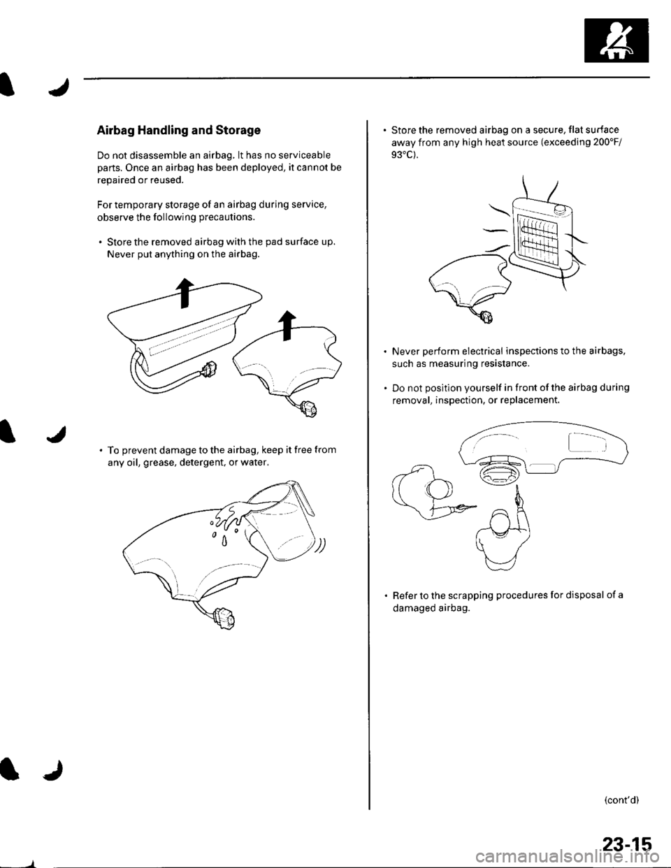
. Store the removed airbag with the pad surface up.
Never put anything on the airbag.
To prevent damage to the airbag, keep it free from
any oil, grease, detergent, or water,
23-15
. Store the removed airbag on a secure, flat surface
away from any high heat source (exceeding 200'Fi
Never perform electrical inspections to the airbags,
such as measuring resistance.
Do not position yourself in front of the airbag during
removal, inspection, or replacement.
Refer to the scrapping procedures for disposal of a
damaged airbag.
(cont'd)
Page 1024 of 1139

I
J
Wiring Precautions
Some of the SRS wiring can be identified by a special
yellow outer covering, and the SRS connectors can be
identified by their yellow color.
Observe the instructions described in this section.
. Never attempt to modify. splice, or repair SRS wiring.
lf there is an open or damage in SRS wiring, replace
the harness.
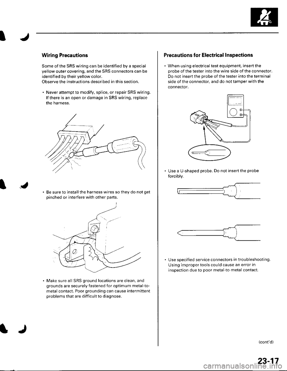
Be sure to install the harness wires so they do not get
Dinched or interfere with other Darts.
Make sure all SRS ground locations are clean, and
grounds are securely fastened for optimum metal-to-
metal contact. Poor grounding can cause intermittent
problems that are difficult to diagnose.
Precautions for Electrical Inspections
. When using electricaltest equipment, insertthe
probe of the tester into the wire side of the connector.
Do not insert the probe of the tester into the terminal
side of the connector, and do not tamper with the
connector.
Use a U-shaped probe. Do not insert the probe
forcibly.
Use specified service connectors in tro u bleshooting.
Using improper tools cou ld cause an error in
inspection due to poor metal-to-metal contact.
(cont'd)
23-17