2003 HONDA CIVIC license plate
[x] Cancel search: license platePage 25 of 1139

t
v
2-13
o
o
a
ItemMeasurementOualilicationSpecitication
ELECTRICAL
RATINGS
Battery12V 36 AH/5 hours
Sta rter12 V-.1.1 kW, 1.2 kW
Alternator12V 95A,90A
FusesUnder-hood fuse80 A, 60 A, 50 A, 40 A, 30 A, 20 A, 15 A, 10 A, 7.5 A
Under'dash Iuse30 4,20 a, 15 A, 10 A,7.5 A
Light bulbsHeadlight high
beam
'12 v.' 60 w
Headlight low
beam
12V 55W
Frontturn signal
liqhts
12V 21W
Front parlinq lights12V 5W
Bear turn signal
lights
12V " 21W
FronVrear side
marker lights
12V 5W
Brale/taillighls12V 21/5W
High moLrnt brake
light
12V 5W
Back up lights12V 21W
License plate light12V 5W
Ceiling light'12 v'.8 w
Cargo area light12V 5W
Spotlights12V 5W
Gauge lights
Indicator lightsLED
Side turn signal
light
12V 5W
Page 831 of 1139

\Body Electrical
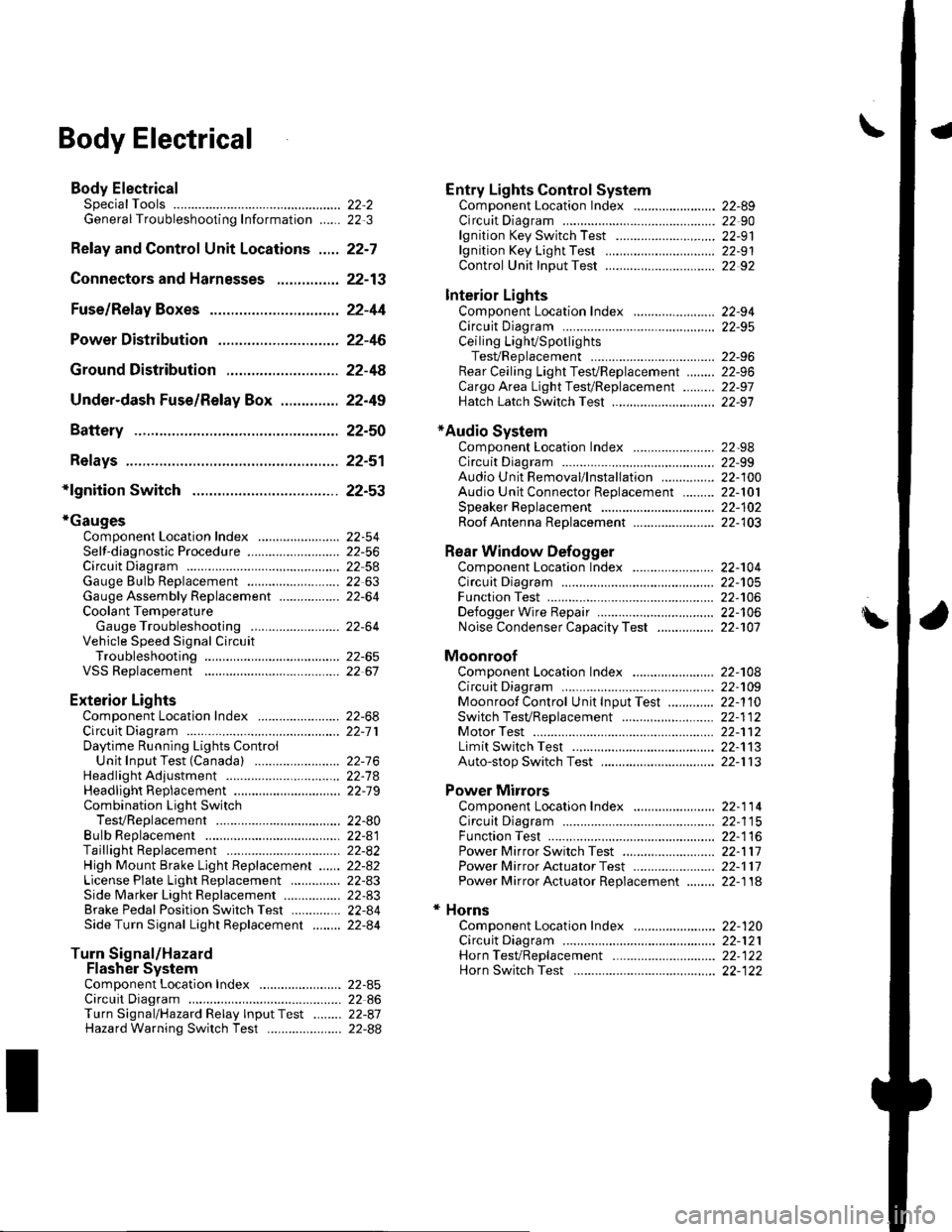
Body ElectricalSpecialToolsGeneral Troubleshooting tntorrnaiion.'......
Relay and Control Unit Locations .....
Connectors and Harnesses
Fuse/Relay Boxes ...............................
Power Distribution .............................
Ground Distribution ...........................
Under-dash Fuse/Relay Box ..............
Battery ..............
Relays ................
*lgnition Switch ..............
*Gauges
Component Location Index .......................Self-diagnostic Procedure ..........................Circuit DiagramGauge Bulb Replacement ..........................Gauge Assembly ReplacementCoolant Temperature
Gauge Troubleshooting .... ....................Vehicle Speed Signal CircuitTroubleshootingVSS Replacement
Exterior LightsComponent Location Index .......................Circuit DiagramDaytime Running Lights ControiUnit Input Test (Canada) ........................Headlight Ad,ustment .................. .. .....Headlighr Replacement ..............................Combination Light SwitchTest/ReplacementBulb ReplacementTaillight Replacement ..........................High Mount Brake Light Replacement ......License Plate Light Replacement ..............Side Marker Light Replacement ................Brake Pedal Position Switch Test ..............Side Turn Signal Light Replacement ........
Turn Signal/HazardFlasher SystemComponent Location Index .......................Circuit DiagramTurn Signal/Hazard Relay lnputTest ........Hazard Warning Switch Test
22,3
22-7
22-13
22-44
22-46
22-4A
22-49
22-50
22-51
22-53
22-5422-5622-5422 6322-64
22-64
22-6522 61
22-6822--71
22-7 622-7422-79
22-AO22-4122-8222-4222-4322-4322-4422-84
22-8�522 A622-8722-88
22-10422-105
22-10622-107
Entry Lights control systemComponent Location Index ....................... 22-89Circuit Diagram ......... 22 90lgnition Key Switch Test .....................,...... 22-9'llgnition Key Light Test ............................... 22-91Control Unit Input Test ..........,.................... 22 92
Interior LightsComponent Location Index ....................... 22-94Circuit Diagram ......... 22-95Ceiling LighVSpotlightsTesVReplacement ................................... 22-96Rear Ceiling Light TesVReplacem ent ........ 22-96Cargo Area Light Test/Replacem ent ......... 22-97Hatch Latch Switch Test ..,..,....................... 22-97
*Audio SystemComponent Location Index ....................... 22-98Circuit Diagram ......... 22,99Audio Unit Removal/lnstallation ............... 22-1OOAudio Unit Connector Replacement ......... 22-101Speaker Replacement ................................ 22-102Roof Antenna Rep1acement ....................-.. 22-103
Rear Window DefoggerComponent Location Index ...........Circuit Diasram .. ....... .. ..... ....... ...:::::.::.::.Function TestDefogger Wire Repair .................................Noise Condenser CapacityTest ................
MoonroofComponent Location Index ....................... 22-1OBCircuit Diagram ......... 22-109Moonroof Control Unit Input Test ............. 22-'l10Switch TesVReplacement ........,.....,........... 22-1 12Motor Test ................. 22-112Limit Swilch Test ...... 22-'l'13Auto-stop Switch Test ................................ 22-1 13
Power MirrorsComponent Location Index ....................... 22-114Circuit Diagram ......... 22-115Function Test ............. 22-116Power Mirror Switch Test .......................... 22-ll7Power Mirror Actuator Test ....................... 22-117Power Mirror Actuator Replacement ........ 22-11A
* HornsComponent Location Index ....................... 22-120Circuit Diagram ......... 22-121Horn TesVReplacement ...........................-. 22-122Horn Switch Test .,.... 22-122
\
Page 870 of 1139

Hatch Wire Harness
Connector or TorminalCavitiesLocationConnects toNotesHatch latch switchHatch lock actuatorHigh mount brake lightLicense plate light connector ALicense plate light connector BRear window de{ogger connector A
Bear window detogger connector B()Bear window wiper moto.c553
c554
7
8
I3
10
62
l
222221
1
412
2
Middle o{ hatchMiddle of hatchBehind high mount brake lightMiddle of hatchMiddle of hatchRight C-pillar
Left C-pillar
Middle of hatchRight quaner panel
Right quaner panel
Floor wire harness (see page22-341Floor wire harness (see page)2-34\
22-39
Page 877 of 1139

Power Distribution
Fuse to Components lndex
Under-hood Fuse/Relay Box
Fuse
Number
AmpsWire ColorComponent(sl or Circuit(s) Protected
'I204BLUI/ELCondenser fan motor
BLU/REDAy'C compressor clutch
15AWHT/GRNDash lights, Front parking lights, Front side marker lights, License plate
liqht, Rear side marker liqhts, Tailliqhts
7.5AWHT/BLUCarqo area liqht, Ceilinq liqhts. lqnition Kev liqht. Sootliohts
204BLU/BLKRadiator fan motor
510AWHT/BLKTurn siqnal/hazard relav, Turn siqnal liqhts
15AWHT/BLKCKP sensor, ECM, IAC valve, lmmobilizer control unit-receiver, Injectors,
PGM-FI main relav 1 and 2. TDC sensor
715AWHT/GRNBrake lights, Brake signals (to ABS modulator-control unit, Cruise control
unit, ECM)
BLU/REDi1 Orns
820AWHT/GRNABS modulatorcontrol unit
910AWHT/REDAudio unit, Data link connector (DLC), Gauge assembly, lmmobilizer
control unit-receiver, lmmobilizer indicator light. Keyless receiver unil,
lvlultiDlex control unit
1040AWHT/REDABS modulator-control unit
1130AB LK/YE LNoise condenser, Rear window defoqqer
40ABLU^^/HTBlower motor
IJ40AWHT/BLKNo. 7 fuse (in the under-dash fuse/relav box), Power window relav
1440AWHT/REDNo.2 and No.3 fuses (in the under-dash fuse/relav box)
t515AREDI/ELDaytime running lights control unit (Canada), Daytime running lights relay
{Canada), Hioh beam indicator liqht. Left headliqht
16204WHTMultiplex control unit
1715AREDDavtime runninq liqhts control unit (Canada). Rioht headlioht
1860AWHTiBLUEPS control unit
1980ABatterv. Power distribution
2040A'
50A'?
WHTlgnition switch (BAT)
* 1: USA" 2. Canada
O: Spare fuse
t t"| lll Itt 4t I
l l---- E'l E,l E,l r--r r---r t__J i; i6'!/'
E,l E,l E,l Eol E l f__--lI l'lr]n | |I r L__J,a ,..r^{-------l^-,
n[:]$"Lrt " N2, nf - r^l
22-46
Page 879 of 1139

Ground Distribution
Ground to Components Index
GroundComponent or circuit qrounded
Batterv, Transmission housinq
E ngine
G 101ECM (PG is BLK; LG is BRN/YEL)
BLK: IAC valve, lgnition coils, Vehicle speed sensor, VTEC solenoid valve
BRNA/EL: Camshaft oosition (CMP) sensor. CKP sensor, TDC sensor. VTEC oil pressure switch
G 15'�]EPS control unit
G201ELD unit. Multiplex control inspection connector, Multiplex control unit, Power window relay, Rear
window washer motor, Right front parking light, Right front side marker light, Right front turn signal
light, Turn signal/hazard relay, Washer fluid level sensor (Canada) , Windshield washer motor,
Windshield wiDer motor
G202ABS modulator-control unit
G301
G401
Blower motor relay, Brake fluid level switch, Condensor fan motor, Cruise control actuator, Left front
parking light, Left front side marker light, Left front turn signal light, Radiator fan motor, Radiator fan
swrtcn
Combination liqht switch, lqnitlon kev srvitch, Wiper/wasfrer sr,virch
G402Left and riqht airbaq sensors, SRS unit
G 451Data link connector (DLC)
G501Clutch interlock switchm Clutch pedal position switch (for cruise control), Cruise control main switch,
Cruise control unit, Daytime running lights control unit (Canada), Driver's door lock knob switch,
Driver's door lock switch, Driver's power window motor, Heater control panel, Left power mirror
defogger (Canada), left side turn signal light, Moonroof control unit, Monroof open and close relays,
Moonroof position sensor '1, Moonroof seitch, Power mirror switch, Power transistor, Power window
master switch. SDotliqhts
G502Accessory power socket, Gauge assembly, Keyless receiver unit, lvlultiplex control unit, Right power
mirror defogger {Canada)
G503Audio unit
G551Driver's seat belt switch, Fuel gauge sending unit, Fuel pump, Memory erase signal (IMES) connector,
OPDS unit. Rioht seat belt switch
G552High mount brake light, License plate lights, Rear window defogger, Rear window defogger noise
condenser. Rear window wioer motor, Hatch latch switch
Back-up lights, Brake lights, Rear side marker lights, Rear turn signal lights, Rear window wiper noise
condenser, Rear window wiper intermittent control unit, Taillights
22-48
Page 900 of 1139

-a-.,_
z
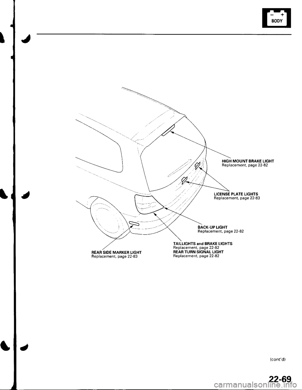
REAR SIDE MARKER LIGHTReplacement, page 22-83
HIGH MOUNT BRAKE LIGHTReplacement, page 22-82
LICENSE PLATE LIGHTSReplacement, page 22-83
BACK.UP LIGHTReplacement, page 22-82
TAILLIGHTS snd BRAKE LIGHTSReplacement, page 22-82REAR TURN SIGNAL LIGHTBeplacement, page 22-82
(cont'd)
22-69
Page 914 of 1139

License Plate Light Replacement
1.Remove the hatch lower trim panel (see page 20-
Pullthe license plale light assembly out. and
disconnect the 2P connector (A) from the light.
License Plate Light: 5Wx2
3.
4.
'[-J^,^f , t lo \
+tiP'-t \-J'fl^
"/ \==-^
Separate the lens (B) and housing (C), then remove
the bulb.
lnstallthe light in the reverse order of removal.
Side Marker Light Replacement
1. Carefully pry the light (A) outofthe rear bumper,
and disconnect the 2P connector (B) from the light.
Be careful not to damage the rear bumper.
Side Marker Light:5W
2.Remove the bulb socket (A) by turning it 45'
counterclockwise. then reolace the bulb.
22-83
Page 987 of 1139

Keyless/Power Door Lock System
Control Unit Input Test (cont'dl
5. Reconnect all connections to the underdash fuse/relay box, and make these input tests at the appropriate connectors on the under-dashfuse/relay box.
'lfanytestindicatesaproblem,findandcorrectthecause,thenrecheckthesystem.. lf all the inputtests prove OK, goto step 6.
CavitvWireTest conditionTest: Desired resultPossible ca use if result is notobtainedc1'l8LUUnder all conditionsAftach to ground:Parking, side marker, licenseplate lights, and tajllights shouldcome on.
Blown No.2 (15A)fuse in the underhood fuse/relay boxFaulty taillight relayFaulty under-dash fuse/relay boxAn onen in rhc wireBLU/BEOUnder all conditionsAttach to ground:Headlights should come on.Blown No. 15 or 17 (15A)fuse in theunderhood fuse/relay boxFaulty headlight relay '1 or 2An ooen in the wireJ2WHT/REDUnder all conditionsCheck for voltage to ground:There should be battery voltage.Blown No.9 (15A)fuse in the under-hood fuse/relay boxAn oncn in thc wircBLKUnder all conditaonsCheck for voltage to ground:Thcre shouln hc 1 V or lpqsPoor ground (G501)An ooen in the wireJ6OBNUnder allconditionsAttach to ground:The horns should sound.Blown No. 7 (15A)fuse in the underhood fuse/relay boxFaulty horn relayFaulty hornsAn 6nen in rhe wireJ7Under all conditionsCheck for voltage to ground:There should be battery voltage.Elown No. 16 (20A)fuse in the underhood fuse/relay boxAn oocn in ihc wi.cP18BEDHatch openCheck for voltage to ground:There should be 1 V or less.Poor ground (G552)Faulty hatch latch switchAn oncn in rhc wirFHatch closedCheck for voltage to groundlThere shoul.l he 5 V or moreFaulty hatch latch switch
GBNDriver's door openCheck for voltage to g.ound:There should be 1 V or less. Faulty driver's door switch. An ooen in the wireDriver's door closedCheck for voltage to ground:There should be 5 V or more.Faulty driver's door switchShort to oroundo4LT GRN/REDPassenger's door openCheck for voltage to ground:There should be 1 V or less.Faulty passenger's door switchAn ooen inthewirePassenger's door closedCheck for voltage to groundlThere should be sVor more
. Faulty passenger's door switch. Short to oroundX5REDAVHTlgnition key inserted intothe ignition swhchCheck for voltage to ground:There should be 1 V or less.Poor ground {G401)Faulty ignition key switchAn ooen inthewirelgnition key removed fromrhe ionition switchCheck for voltage to ground:There should be 5 V or more.Faulty ignition key switchShort to oroundY1WHT/BLKDriver's door lock knobswitch unlockedCheck for voltage to groundlThere should be 1 V or less.Poorground (G50'l)Faulty driver's door lock knob switchAn open in the wireDriver's door lock knobCheck for voltage to groundlIhere should be 5 V or more.Faulty driver's door lock knob switchShort to oroundY8YEUREDDriver's door lock knobswitch lockedCheck for voltage to groundlThere should be 1 V or less.Poorground (G50'l)Faulty driver's door lock knob switchAn oncn inihewireDriver's door lock knobswitch unlockedCheck for voltage to ground:There should be 5Vor more' Faulty driver's door lock knob sw;tch. Shorr to oroundY10WHT/GRNDrtver's door lock switchunlockedCheck for voltage to groundlThere should be 1 V or less.Poorground (G501iFaulty driver's door lock switchAn ooen in the wireDriver's door lock switch inCheck for voltage to ground:Therc shorl.l be 5V or m6rpFaulty driver's door lock switchShort to o rolrndY12WHT/BLUDriver's door lock switchlockedCheck for voltage to ground:There should be 'l V or less.Poor ground (G501)Faulty driver's door lock switchAn oDen in the wireDriver's door lock switch inCheck tor voltage to ground:There should be 5Vor moreFaulty driver's door lock switch
22-156
J