Page 158 of 1139
Engine Block
Piston, Pin, and Connecting Rod Replacement (cont'd)
Reassembly
1. Install a piston pin snap ring (A).
Coat the piston pin bore in the piston, the bore in
the connecting rod, and the piston pin with engine
oil.
Heat the piston to about 158"F (70'C).3.
7 -20
\
4. Install the piston pin (A). Assemble the piston (B)
and connecting rod (C) with the arrow (D) and the
embossed mark (E) on the same side. -
Install the remaining snap ring (F).
Turn the snap rings in the ring grooves untilthe
end gaps are positioned at the bottom of the piston.
(
5.
6.
I
Page 159 of 1139

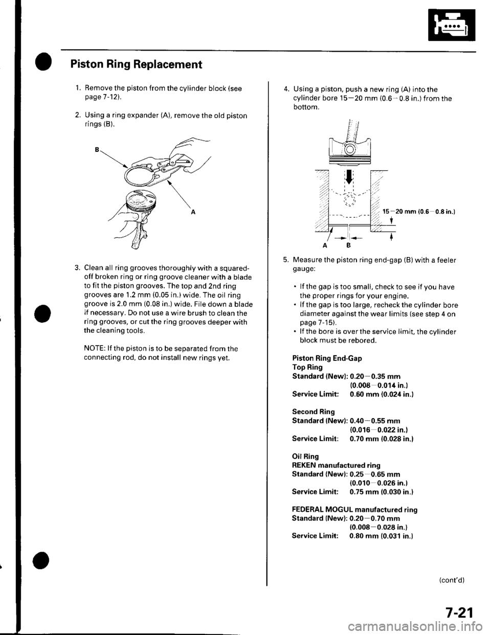
Piston Ring Replacement
1. Remove the piston {rom the cylinder block (see
page 7 -121.
2. Using a ring expander (A), remove the old piston
rings (B).
3. Clean all ring grooves thoroughly with a squared-
off broken ring or ring groove cleaner with a blade
to fit the pislon grooves. The top and 2nd ringgrooves are 1.2 mm (0.05 in,)wide. The oil ringgroove is 2.0 mm (0.08 in.) wide. File down a blade
lf necessary. Do not use a wire brush to clean the
ring grooves, or cut the ring grooves deeper with
the cleaning tools.
NOTE: lf the piston is to be separated from the
connecting rod, do not install new rings yet.
4. Using a piston, push a new ring (A) into the
cylinder bore 15-20 mm {0.6-0.8 in.) from the
bottom.
15 20 mm (0.6 0.8 in.)
I
Measure the piston ring end-gap (B) with a feelerga uge:
. lf the gap istoo small, checkto see if you have
the proper rings for your engine.. lf the gap istoo large, recheckthecylinder bore
diameter against the wear limits (see slep 4 onpage 7-15).. lf the bore is overthe service limit, the cylinder
block must be rebored.
Piston Ring End-Gap
Top Fing
Standard (Newl: 0.20 0.35 mm(0.008 0.014 in.l
Service Limit: 0.60 mm (0.024 in..
Second Ring
Standard (New): 0.40-0.55 mm
{0.016 0.022 in.)
Service Limit: 0.70 mm (0.028 in.)
Oil Ring
REKEN manufactured ring
Standard (Newl: 0.25 0.65 mm(0.010 0.026 in.l
Service Limit: 0.75 mm (0.030 in.)
FEDERAL MOGUL manufactured rino
Standard lNew): 0.20 0.70 mm
{0.008 0.028 in.}
Service Limit: 0.80 mm (0.031 in.)
B
(cont'd)
7-21
Page 160 of 1139

Engine Block
Piston Ring Replacement (cont'd)
6. Install the top ring and second ring as shown.The
top ring (A) has a 1R mark or no mark and the
second ring (B) has a 2R mark or 2ND mark. The
marks must be facing upward.
o\,"16.
s =:-=2
\5
V"
12-)V
P'ffi+a\aq*-pogd
.ZR,
V
Piston Ring oimensions:
t ToP Ring {Standardl:| | o A: 3.1 mm {0.12 in.l
| | J - B:1.2 mm {0.05 in.)Socond Ring {Standard):A:3.4 mm {0.13 in.}- A- B:'1.2 mm (0.05 in.i
7, Rotate the rings in their grooves to make sure they
do not bind.
7-22
\{
8. Position the ring end gaps as shown:
OIL RING GAPAbout 90'SECOND RING GAP
About 45"
OIL RING GAPTOP RING GAPand SPACERRING GAPPISTON PIN
9. After installing a new set of rings, measure the
ring-to-groove clearances:
Top Ring Clearance
Standard {New}:
0.035-0.060 mm {0.0014-0.0024 in.)
Service Limit: 0.13 mm (0.005 in.)
Second Ring Clearance
Standard lNew):
REKEN manutactured ring
0.030-0.055 mm (0.0012-0.0022 in.)
FEDERAL MOGUL manulactured ring
0.025-0.060 mm (0.001 0-0.0024 in.)
Service Limit: 0.13 mm (0.005 in.)
{
Page 161 of 1139

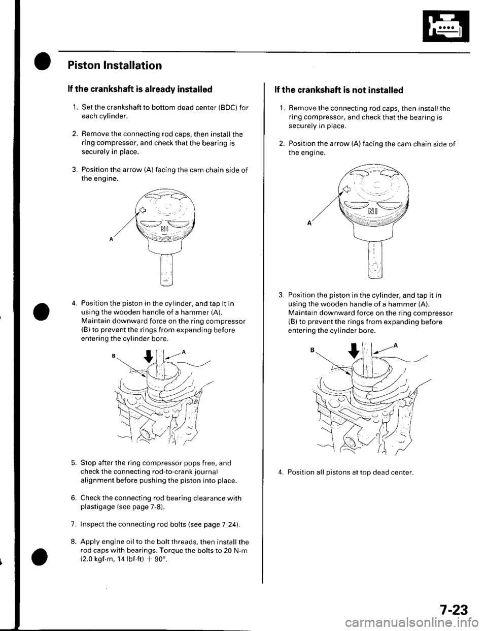
Piston Installation
lf the crankshaft is already installed
1. Setthe crankshaftto bottom dead center (BDC) for
each cylinder.
2. Remove the connecting rod caps, then install the
ring compressor, and check that the bearing is
securely in place,
3. Position the arrow {A) facing the cam chain side of
rne engtne.
Position the piston in the cylinder, and tap it in
using the wooden handle of a hammer (A).
N4aintain downward force on the ring compressor(B) to prevent the rings from expanding before
entering the cylinder bore.
Stop after the ring compressor pops free, and
check the connecting rod-to-crank journal
alignment before pushing the piston into place.
Check the connecting rod bearing clearance withplastigage (see page 7-8).
lnspect the connecting rod bolts (see page 7 241.
Apply engine oil to the bolt threads, then install the
rod caps with bearings. Torque the bolts to 20 N.m
{2.0 kgf m, 14 lbf ft) + 90'.
6.
7.
2.
1.
lf the crankshaft is not installed
Remove the connecting rod caps. then install the
ring compressor, and check that the bearing is
securely in place.
Position the arrow (A)facing the cam chain side of
Ine engrne.
Position the piston in the cylinder, and tap it in
using the wooden handle of a hammer (A),
Maintain downward force on the ring compressor(B) to prevent the rings from expanding before
entering the cylinder bore.
4. Position all pistons attop dead center.
\--lno n\-.--l. ^u t
>-*/zi
.,.'_\pf{
wr
(( 'V,/ :
7-23
Page 175 of 1139
Oil Pump Removal
1. Setthe No. 1 piston attop dead center {TDC) {see
step 1 on page 6-12).
2. Remove the oil pan(seepageT-11).
3. Remove and discard the oil pumpchaintensioner.
4. To hold the rear balancer shaft, insert a 6 mm pin
driver (A) into the maintenance hole in the lower
balancer shaft holder and through the rear balancer
shaft.
5. Loosen the oil pump sprocket mounting bolt.
6. Remove the oil pump sprocket (A), then remove the
oil pump (B).
(cont'd)
8-9
Page 180 of 1139
Engine Lubrication
Oil Pump Overhaul (cont'd)
13. lnstallthe pump housing.
6x1,0mm12 N.m(1.2 kgt.m,8.7 lbf.ft)
8-14
!
Oil Pump Installation
1. Make sure the No. 1 piston is at TDC (see step 1 on
page 6-12).
2. Align the dowel pin{A} on the rear balancer shaft
with the mark (B) on the oil pump.
To hold the rear balancer shaft, insert a 6 mm pin
driver {A) into the maintenance hole in the lower
balancer shaft holder and through the rear balancer
shaft.\,-
9%ttrc
+:.:4.4 / t \
o/.-lY\
:aa:'
-rr
dv
f,o-;
Page 401 of 1139

Clutch
Clutch Pedal, Clutch
Adjustment
NOTE:. To check the clutch pedal position switch(see page 4-45).. To check the clutch interlock switch (see page 4-6).. Remove the driver's side floor mat before adjusting
the clutch pedal.. The clutch is self-adjusting to compensate for wear.. lf there is no clearance betweenthe mastercylinderpiston and push rod, the release bearing will be held
against the diaphragm spring. which can result in
clutch slippage or other clutch problems.
1. Loosen the clutch pedal position switch locknut (A),
and back off the clutch pedal position switch (B)
until it no longer touches the clutch pedal (C).
J9.8 N.m(1.0 kgf.m,7.2 lbf.ft)
A9.8 N.m11.0 kgf.m, 7.2 lbf.ft)
o18 N.m{1.8 kgf.m,13 tbf.ftl
Loosen the clutch push-rod locknut (D). and turn
the push rod (E) in or out to get the specified height(F), stroke (G). free play (H) and disengagement
height (l) atthe clutch pedal.
Clutch PedalStroke: 130 140 mm(5.12 5.51 in.l
Clutch Pedal Free Play: l0 16 mm (0.39-0.63 in.)
Clutch Pedal Height: 193 mm (7.60 in.)
Disengagement
Height: 115 mm (4.53 in.)
Between Floor And
Carpet Height(Approximate Valuel: 38 mm {1.50 in.l
12-4
Pedal Position Switch, and Clutch Interlock Switch
3. Tighten the clutch push-rod locknut (D).
4. With the clutch pedal released. turn the clutchpedal position switch (B) in until it contacts the
clutch pedal (C).
5. Turn the clutch pedal position switch {B) in an
additional 3/4 to 1 turn.
6. Tighten the clutch pedal position switch locknut (A).
7. Loosen locknut (J)and the clutch interlock switch(K).
8. Press the clutch pedal to the floor.
9. Release the clutch pedal 10 'l6mm(0,39 0.63in.)
from the fully pressed position, and hold it there.
Adjust the position of the clutch interlock switch (K)
so that the engine will start with the clutch pedal in
thls position.
10. Tighten the clutch interlock switch locknut (J).
Page 599 of 1139

Gonventional Brake Components
ComponentProcedureAlso check for:
l\4aster CylinderLook for damage or signs of fluid leakage at;. Reservoir or reservoir grommets
. Line joints
. Between master cvlinder and booster
Brake HosesLook for damage or signs of fluid leakage at:. Line joints and banjo bolt connections. Hoses and lines. also inspect for twisting or
damaqe
Bulging, twisted or bent lines.
CaliperLook for damage or signs of fluid leakage at:. Piston seal. Banjo bolt connections. Bleeder screw
Seized or sticking caliper pins.
ABS l\ilodulatorLook for damage or signs of fluid leakage at:. Line joints
. Modulator
Brake System Inspection and Tests
Brake System Test
Brake pedal sinks/fades when braking
1. Start the engine, and let it warm up to operating temperature.
2. Attach a 2-inch pieceof masking tape along the bottom of the steering wheel, and draw a horizontal reference
mark across it.
With the transmission in Neutral, press and hold the brake pedal lightly, then release the parking brake.
While still holding the brake pedal, hook the end of the tape measure behind it. Then pull the tape up to the
steering wheel, noting where the tape measure lines up with the reference mark you made on the masking tape.
Apply steady pressure to the brake pedal for 3 minutes.
Watch the tape measure.
. if it moves less than 10 mm, the master cylinder is OK.
. if it moves more than 10 mm replace the master cylinder.
t-
3.
5.
6.
19-4