Page 1364 of 4378
70. Install the RH and LH special tool.
71. Using the special tool, remove the engine from the stand.
72. Install the separator plate.
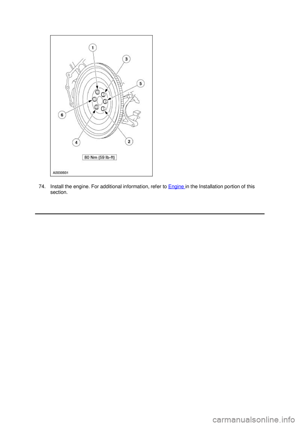
73. Install the flywheel. 15 — To body
16 — To heated oxygen sensor (2)
17 — Engine bulkhead connector
18 — To low coolant sensor
19 — To body
20 — To power distribution box
21 — To body �K�l�j . 24 �b�a
252003 Mustang Workshop Manual
17. 11. 2011file:///C:/Ford/2000 - 2004/tsocache/SHEF_4464/S3B~us~en~ ...
Page 1365 of 4378
74. Install the engine. For additional information, refer to
Engine in the Installation portion of this
section. �K�l�j . 25 �b�a
252003 Mustang Workshop Manual
17. 11. 2011file:///C:/Ford/2000 - 2004/tsocache/SHEF_4464/S3B~us~en~ ...
Page 1366 of 4378
INSTALLATION
Engine
SECTION 303-
01B: Engine — 4.6L (2V) 2003 Mustang Workshop Manual Special Tool(s)
Spreader Bar
303-
D089 (D93P-6001- A3) Support Bracket, Engine
303-
639 Lifting Bracket, Engine
303-
D087 (D93P-6001- A1) Lifting Bracket, Engine
303-
D088 (D93P-6001- A2) Lifting Bracket Set, Engine
303-
D074 (D91P-6001- A)
Material Item Specification
Metal Surface Cleaner
F4AZ-
19A536- RA or equivalent WSE-
M5B392-
A Silicone Gasket and Sealant
F7AZ-
19554- EA or equivalent WSE-
M4G323-
A4 Super Premium SAE 5W-20
Engine Oil
XO- 5W20- QSP or equivalent WSS-
M2C153-
H Premium Engine Coolant
E2FZ-
19549- AA (In Canada
CXC- 10; In Oregon F5FZ-
19549- CC) or equivalent ESE-
M97B44-
A �K�l�j . 1 �b�a
132003 Mustang Workshop Manual
17. 11. 2011file:///C:/Ford/2000 - 2004/tsocache/SHEF_4464/S3B~us~en~ ...
Page 1367 of 4378
1.
NOTE: Adjust the transmission support jack as necessary to aid in the installation of the engine.
Using the special tool, install the engine.
2. Connect the transmission wiring to the bracket during installation.
3. Remove the special tool.
4. Install the special tool. �K�l�j . 2 �b�a
132003 Mustang Workshop Manual
17. 11. 2011file:///C:/Ford/2000 - 2004/tsocache/SHEF_4464/S3B~us~en~ ...
Page 1368 of 4378
5.
NOTE: This step will allow the installation of the exhaust manifold through the bottom and
access for the removal of the engine lift brackets.
Using a suitable floor crane raise the engine.
6. Remove the RH and LH special tool.
7. Install new gaskets and the exhaust manifolds, tighten the nuts in the sequence shown.
8. Lower the engine, remove the special tool. �K�l�j . 3 �b�a
132003 Mustang Workshop Manual
17. 11. 2011file:///C:/Ford/2000 - 2004/tsocache/SHEF_4464/S3B~us~en~ ...
Page 1375 of 4378
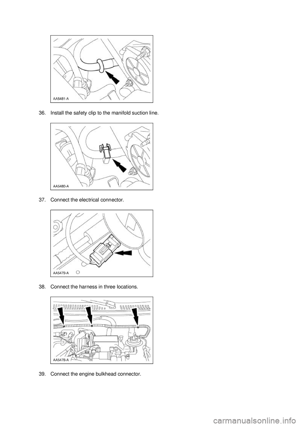
36. Install the safety clip to the manifold suction line.
37. Connect the electrical connector.
38. Connect the harness in three locations.
39. Connect the engine bulkhead connector. �K�l�j . 10 �b�a
132003 Mustang Workshop Manual
17. 11. 2011file:///C:/Ford/2000 - 2004/tsocache/SHEF_4464/S3B~us~en~ ...
Page 1377 of 4378
44. Connect the upper radiator hose from the water outlet adapter.
45. Connect the fuel lines. For additional information, refer to Section 310
- 00 .
46. Install the battery. For additional information, refer to Section 414 - 01 .
47. Install the air cleaner and outlet tube. For additional information, refer to Section 303 - 12 .
48. Install the degas bottle. For additional information, refer to Section 303 - 03A or
Section 303 -
03B .
49. Fill the fluids to the correct levels.
50. Start the engine and check for leaks. Stop the engine and recheck the fluid levels.
51. Recharge the A/C system. For additional information, refer to Section 412 - 00 .
52. Install the hood. �K�l�j . 12 �b�a
132003 Mustang Workshop Manual
17. 11. 2011file:///C:/Ford/2000 - 2004/tsocache/SHEF_4464/S3B~us~en~ ...
Page 1379 of 4378
 2003 Mustang Workshop Manual General Specifications
Item Specification
Lubricants and Sealants
Motorcraft Premium Engine Coolant VC-4-")
SPECIFICATIONS
SECTION 303-
01C: Engine — Cobra 4.6L (4V) 2003 Mustang Workshop Manual General Specifications
Item Specification
Lubricants and Sealants
Motorcraft Premium Engine Coolant VC-4-
A
(In Oregon VC- 5, In Canada CXC- 10) ESE-
M97B44- A Motorcraft Premium Gold Engine Coolant VC-7-
A
(In Oregon VC-7- B) WSS-
M97B51- A1 SAE 5W-
20 Engine Premium Synthetic Blend Engine Oil
XO- 5W20- QSP WSS-
M2C153- H Metal Surface Cleaner
F4AZ-
19A536- RA WSE-
M5B392- A Silicone Gasket and Sealant F7AZ-19554-
EA WSE-
M4G323- A4 Pipe Sealant with Teflon® D8AZ-19554-
A WSK-
M2G350- A2 Threadlock 262 E2FZ-19554-
B WSK-
M2G351- A6 Engine
Displacement 4.6L (4V) (281 CID)
Number of cylinders 8
Bore 90.2 mm (3.55 in)
Stroke 90.0 mm (3.54 in)
Firing order 1-3-7-2-6-5-4-
8 Oil pressure 138-310 kPa
Oil capacity
6 ±
0.25 a Compression ratio 8.5:1
Cylinder Head and Valve Train
Cylinder head gasket surface flatness 0.10 mm (0.004 inch) max. overall
Combustion chamber volume 52.6 ±
0.5 cm Valve arrangement (front to rear)
b
Intake (left hand): S-P-S-P-S-P-S-P
Valve arrangement (front to rear)
Exhaust (left hand): E-E-E-E-E-E-E-E
Valve arrangement (front to rear)
Intake (right hand): P-S-P-S-P-S-P-S
Valve arrangement (front to rear)
Exhaust (right hand): E-E-E-E-E-E-E-E
Valve guide bore diameter 7.015-
7.044 mm (0.2762- 0.2773 in) Valve stem diameter—
intake 6.975-
6.995 mm (0.2754- 0.2746 inch) Valve stem diameter—
exhaust 6.949-
6.970 mm (0.2744- 0.2736 inch) Valve stem-
to-guide clearance— intake 0.020-
0.069 mm (0.00078- 0.00272 inch) Valve stem-
to-guide clearance— exhaust 0.046-
0.094 mm (0.0018- 0.0037 in) Valve head diameter—
intake 37 mm (1.46 inch) �K�l�j . 1 �b�a
62003 Mustang Workshop Manual
17. 11. 2011file:///C:/Ford/2000 - 2004/tsocache/SHEF_4464/S3B~us~en~ ...

 2003 Mustang Workshop Manual Special Tool(s)
Spreader Bar
303-
D089 (D93P-6001- A3) Support Bracket, Engine
303-
639 Lifting Bracket,")