Page 2663 of 4378
REMOVAL AND INSTALLATION
Disc and Pressure Plate —
4.6L (4V) Engine
1. Disconnect the battery ground cable. For additional information, refer to Section 414 - 01 .
2. Remove the transmission. For additional information, refer to Section 308 - 03C .
3. Remove the starter. 1. Remove the terminal cap.
2. Remove the nuts.
3. Remove the wires and position them aside.
4. Remove the two bolts and the starter.
4. Remove the clutch cable clip, then pull the cable through the clutch housing.
SECTION 308-
01: Clutch 2003 Mustang Workshop Manual Special Tool(s)
Clutch Aligner
308-
020 (T74P-7137- K)
Material Item Specification
Premium Long Life Grease
XG
-1-C ESA-
M1C75- B �K�l�j . 1 �b�a
42003 Mustang Workshop Manual
18. 11. 2011file:///C:/Ford/2000 - 2004/tsocache/SHEF_2308/S3B~us~en~ ...
Page 2665 of 4378
Installation
1. NOTE: Clean the clutch pressure plate and flywheel with a commercial alcohol- based solvent
so surfaces are free from oil film. Do not use cleaners with a petroleum base.
NOTE: Before installing the transmission, the ball stud, the clutch release lever and the input
shaft must be cleaned and lubricated with grease.
To install, reverse the removal procedure.
�zUsing the special tool, align the clutch disc and pressure plate to the flywheel.
2. Tighten the pressure plate bolts in two stages. �zStage 1: Tighten the bolts to 45 Nm (33 lb- ft).
�z Stage 2: Tighten the bolts an additional 60 degrees. �K�l�j . 3 �b�a
42003 Mustang Workshop Manual
18. 11. 2011file:///C:/Ford/2000 - 2004/tsocache/SHEF_2308/S3B~us~en~ ...
Page 2674 of 4378

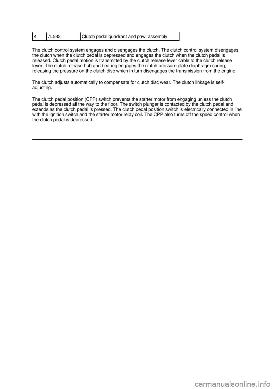
The clutch control system engages and disengages the clutch. The clutch control system disengages
the clutch when the clutch pedal is depressed and engages the clutch when the clutch pedal is
released. Clutch pedal motion is transmitted by the clutch release lever cable to the clutch release
lever. The clutch release hub and bearing engages the clutch pressure plate diaphragm spring,
releasing the pressure on the clutch disc which in turn disengages the transmission from the engine.
The clutch adjusts automatically to compensate for clutch disc wear. The clutch linkage is self-
adjusting.
The clutch pedal position (CPP) switch prevents the starter motor from engaging unless the clutch
pedal is depressed all the way to the floor. The switch plunger is contacted by the clutch pedal and
extends as the clutch pedal is pressed. The clutch pedal position switch is electrically connected in line
with the ignition switch and the starter motor relay coil. The CPP also turns off the speed control when
the clutch pedal is depressed. 4 7L583 Clutch pedal quadrant and pawl assembly �K�l�j . 2 �b�a
22003 Mustang Workshop Manual
18. 11. 2011file:///C:/Ford/2000 - 2004/tsocache/SHEF_2308/S3B~us~en~ ...
Page 2682 of 4378
REMOVAL AND INSTALLATION
Release Cable —
Clutch
Removal
CAUTION: Whenever the clutch release lever cable (7K553) is disconnected for any
reason, such as transmission removal, clutch pedal components or clutch release lever cable
replacement, it is imperative the correct method for installing the clutch release lever cable be
followed. Incorrect installation may damage components or cause system failure.
1. Remove the instrument panel steering column cover. 1. Remove the screws.
2. Remove the instrument panel steering column cover.
2. Remove the instrument panel reinforcement. 1. Remove the screws.
2. Remove the instrument panel reinforcement.
3. Lift the clutch pedal (7519) to its most upward position.
SECTION 308-
02: Clutch Controls 2003 Mustang Workshop Manual �K�l�j . 1 �b�a
52003 Mustang Workshop Manual
18. 11. 2011file:///C:/Ford/2000 - 2004/tsocache/SHEF_2308/S3B~us~en~ ...
Page 2687 of 4378

SPECIFICATIONS
SECTION 308-
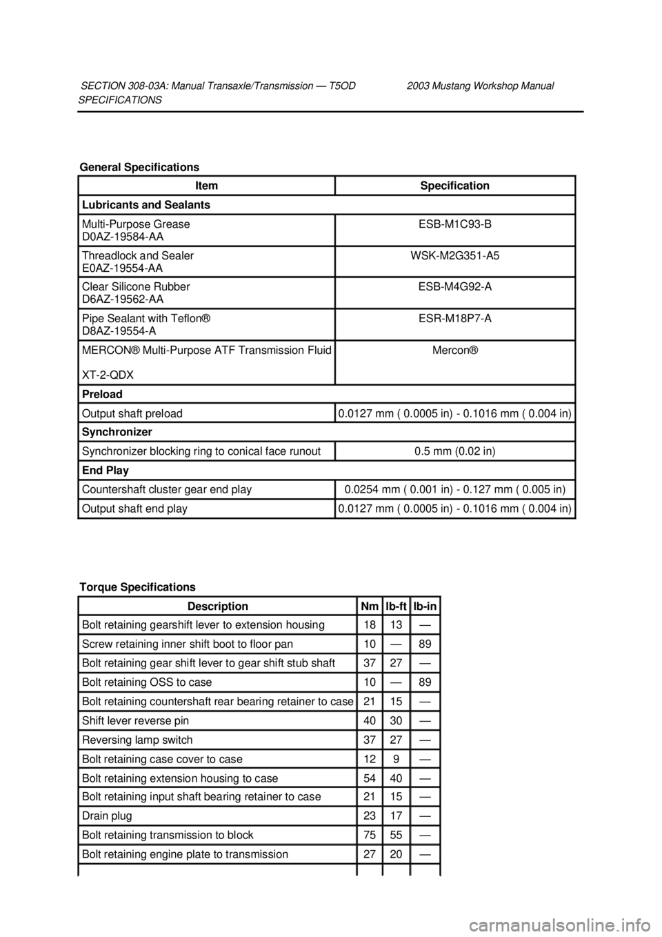
03A: Manual Transaxle/Transmission — T5OD 2003 Mustang Workshop Manual General Specifications
Item Specification
Lubricants and Sealants
Multi-
Purpose Grease
D0AZ- 19584- AA ESB-
M1C93- B Threadlock and Sealer
E0AZ-
19554- AA WSK-
M2G351- A5 Clear Silicone Rubber
D6AZ-
19562- AA ESB-
M4G92- A Pipe Sealant with Teflon®
D8AZ-
19554- A ESR-
M18P7-A MERCON® Multi-
Purpose ATF Transmission Fluid
XT -2-QDX Mercon®
Preload
Output shaft preload 0.0127 mm ( 0.0005 in) - 0.1016 mm ( 0.004 in)
Synchronizer
Synchronizer blocking ring to conical face runout 0.5 mm (0.02 in)
End Play
Countershaft cluster gear end play 0.0254 mm ( 0.001 in) -
0.127 mm ( 0.005 in) Output shaft end play 0.0127 mm ( 0.0005 in) - 0.1016 mm ( 0.004 in)
Torque Specifications Description Nm lb-
ft lb-
in Bolt retaining gearshift lever to extension housing 18 13 —
Screw retaining inner shift boot to floor pan 10 — 89
Bolt retaining gear shift lever to gear shift stub shaft 37 27 —
Bolt retaining OSS to case 10 — 89
Bolt retaining countershaft rear bearing retainer to case 21 15 —
Shift lever reverse pin 40 30 —
Reversing lamp switch 37 27 —
Bolt retaining case cover to case 12 9 —
Bolt retaining extension housing to case 54 40 —
Bolt retaining input shaft bearing retainer to case 21 15 —
Drain plug 23 17 —
Bolt retaining transmission to block 75 55 —
Bolt retaining engine plate to transmission 27 20 — �K�l�j . 1 �b�a
22003 Mustang Workshop Manual
18. 11. 2011file:///C:/Ford/2000 - 2004/tsocache/SHEF_2308/S3B~us~en~ ...
Page 2688 of 4378
Bolt retaining crossmember to frame 41 30 —
Bolt retaining crossmember to transmission support 58 43 —
Nut retaining dual converter Y-
pipe to exhaust manifold 40 30 —
Nut retaining dual converter Y-
pipe flange to muffler 35 26 —
Bolt retaining driveshaft centering yoke to pinion flange 112 83 — �K�l�j . 2 �b�a
22003 Mustang Workshop Manual
18. 11. 2011file:///C:/Ford/2000 - 2004/tsocache/SHEF_2308/S3B~us~en~ ...
Page 2689 of 4378
DESCRIPTION AND OPERATION
Manual Transmission
The T5OD 5-
speed transmission:
�z fifth speed gear functions as an overdrive gear.
�z forward gears are synchronized and helical cut.
�z shift interlock system prevents the engagement of more than one gear. Transmission, Manual Five - Speed SECTION 308-
03A: Manual Transaxle/Transmission — T5OD 2003 Mustang Workshop Manual �K�l�j . 1 �b�a
52003 Mustang Workshop Manual
18. 11. 2011file:///C:/Ford/2000 - 2004/tsocache/SHEF_2308/S3B~us~en~ ...
Page 2692 of 4378

Transmission Identification
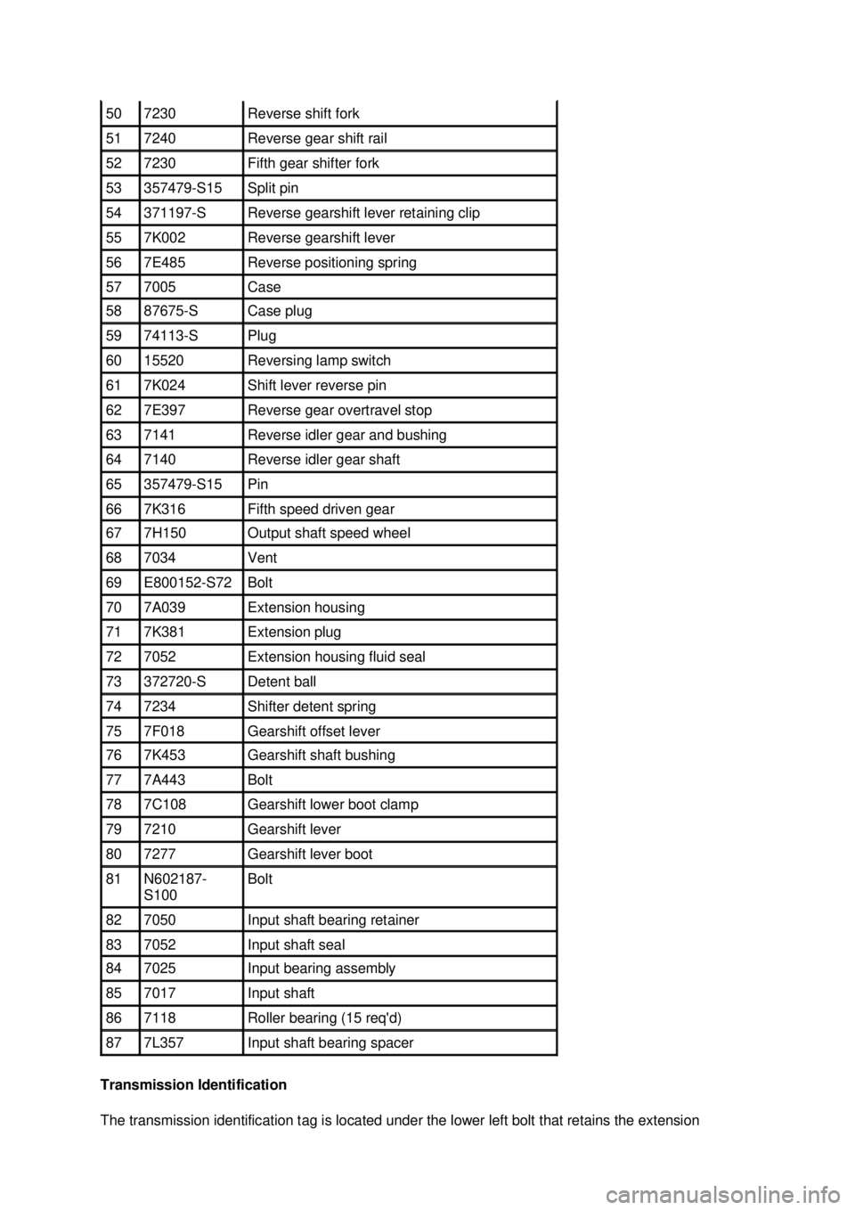
The transmission identification tag is located under the lower left bolt that retains the extension 50 7230 Reverse shift fork
51 7240 Reverse gear shift rail
52 7230 Fifth gear shifter fork
53 357479-S15 Split pin
54 371197-
S Reverse gearshift lever retaining clip
55 7K002 Reverse gearshift lever
56 7E485 Reverse positioning spring
57 7005 Case
58 87675-
S Case plug
59 74113-
S Plug
60 15520 Reversing lamp switch
61 7K024 Shift lever reverse pin
62 7E397 Reverse gear overtravel stop
63 7141 Reverse idler gear and bushing
64 7140 Reverse idler gear shaft
65 357479-S15 Pin
66 7K316 Fifth speed driven gear
67 7H150 Output shaft speed wheel
68 7034 Vent
69 E800152-S72 Bolt
70 7A039 Extension housing
71 7K381 Extension plug
72 7052 Extension housing fluid seal
73 372720-
S Detent ball
74 7234 Shifter detent spring
75 7F018 Gearshift offset lever
76 7K453 Gearshift shaft bushing
77 7A443 Bolt
78 7C108 Gearshift lower boot clamp
79 7210 Gearshift lever
80 7277 Gearshift lever boot
81 N602187-
S100 Bolt
82 7050 Input shaft bearing retainer
83 7052 Input shaft seal
84 7025 Input bearing assembly
85 7017 Input shaft
86 7118 Roller bearing (15 req'd)
87 7L357 Input shaft bearing spacer �K�l�j . 4 �b�a
52003 Mustang Workshop Manual
18. 11. 2011file:///C:/Ford/2000 - 2004/tsocache/SHEF_2308/S3B~us~en~ ...