Page 4116 of 4378
13. Remove the wire harness from its holders.
14. Remove the clockspring.
1. Pry the clockspring retaining clips loose.
2. Remove the clockspring.
Installation WARNING: To reduce the risk of serious personal injury, read and follow all warnings,
cautions and notes at the beginning of the removal procedure.
Vehicles receiving a new clockspring
1. NOTE: A new clockspring is supplied in a centralized position and held there with a key.
Remove the key from the clockspring, holding the rotor in its centralized position. �zDo not allow the clockspring rotor to turn. Vehicles needing clockspring recentering �K�l�j . 5 �b�a
112003 Mustang Workshop Manual
18. 11. 2011file:///C:/Ford/2000 - 2004/tsocache/SHEF_5108/S3B~us~en~ ...
Page 4117 of 4378
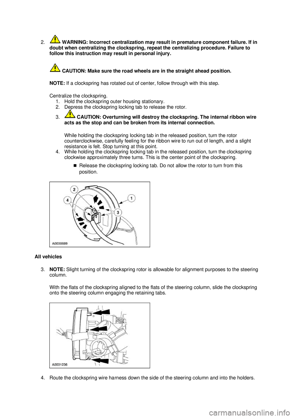
2.
WARNING: Incorrect centralization may result in premature component failure. If in
doubt when centralizing the clockspring, repeat the centralizing procedure. Failure to
follow this instruction may result in personal injury.
CAUTION: Make sure the road wheels are in the straight ahead position.
NOTE: If a clockspring has rotated out of center, follow through with this step.
Centralize the clockspring. 1. Hold the clockspring outer housing stationary.
2. Depress the clockspring locking tab to release the rotor.
3. CAUTION: Overturning will destroy the clockspring. The internal ribbon wire
acts as the stop and can be broken from its internal connection.
While holding the clockspring locking tab in the released position, turn the rotor
counterclockwise, carefully feeling for the ribbon wire to run out of length, and a slight
resistance is felt. Stop turning at this point.
4. While holding the clockspring locking tab in the released position, turn the clockspring
clockwise approximately three turns. This is the center point of the clockspring.
�„Release the clockspring locking tab. Do not allow the rotor to turn from this
position.
All vehicles 3. NOTE: Slight turning of the clockspring rotor is allowable for alignment purposes to the steering
column.
With the flats of the clockspring aligned to the flats of the steering column, slide the clockspring
onto the steering column engaging the retaining tabs.
4. Route the clockspring wire harness down the side of the steering column and into the holders. �K�l�j . 6 �b�a
112003 Mustang Workshop Manual
18. 11. 2011file:///C:/Ford/2000 - 2004/tsocache/SHEF_5108/S3B~us~en~ ...
Page 4118 of 4378
5. Remove the restraint system diagnostic tool from the vehicle harness side of the clockspring
electrical connector.
6. Connect the two clockspring electrical connectors. Position the clockspring electrical connectors onto the bracket.
7. Install the key- in-ignition warning indicator switch.
8. Install the passive anti- theft system (PATS) transmitter.
1. Position the PATS transmitter to the steering column.
2. Install the screw. �K�l�j . 7 �b�a
112003 Mustang Workshop Manual
18. 11. 2011file:///C:/Ford/2000 - 2004/tsocache/SHEF_5108/S3B~us~en~ ...
Page 4121 of 4378
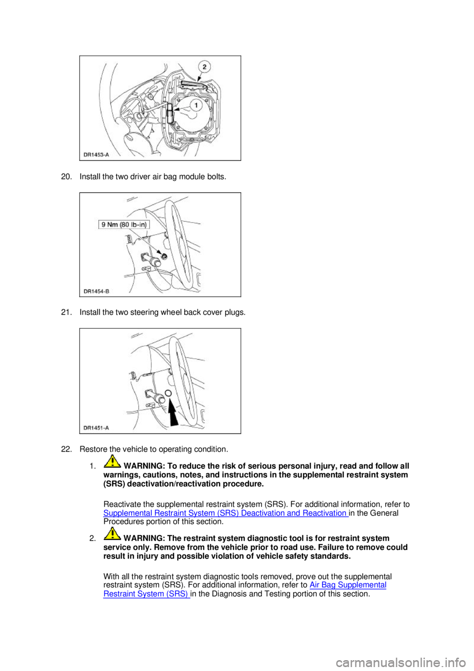
20. Install the two driver air bag module bolts.
21. Install the two steering wheel back cover plugs.
22. Restore the vehicle to operating condition.
1. WARNING: To reduce the risk of serious personal injury, read and follow all
warnings, cautions, notes, and instructions in the supplemental restraint system
(SRS) deactivation/reactivation procedure.
Reactivate the supplemental restraint system (SRS). For additional information, refer to
Supplemental Restraint System (SRS) Deactivation and Reactivation in the General
Procedures portion of this section.
2. WARNING: The restraint system diagnostic tool is for restraint system
service only. Remove from the vehicle prior to road use. Failure to remove could
result in injury and possible violation of vehicle safety standards.
With all the restraint system diagnostic tools removed, prove out the supplemental
restraint system (SRS). For additional information, refer to Air Bag Supplemental Restraint System (SRS) in the Diagnosis and Testing portion of this section. �K�l�j . 10 �b�a
112003 Mustang Workshop Manual
18. 11. 2011file:///C:/Ford/2000 - 2004/tsocache/SHEF_5108/S3B~us~en~ ...
Page 4150 of 4378
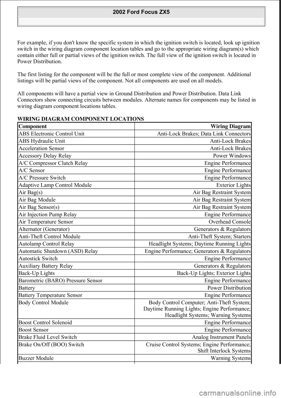
For example, if you don't know the specific system in which the ignition switch is located, look up ignition
switch in the wiring diagram component location tables and go to the appropriate wiring diagram(s) which
contain either full or partial views of the ignition swit ch. The full view of the ignition switch is located in
Power Distribution.
The first listing for the component will be the full or most complete view of the component. Additional
listings will be partial views of the component. Not all components are used on all models.
All components will have a partial view in Gr ound Distribution and Power Distribution. Data Link
Connectors show connecting circuits between modules. Alternate names for components may be listed in
wiring diagram component locations tables.
WIRING DIAGRAM COMPONENT LOCATIONS
ComponentWiring Diagram
ABS Electronic Control UnitAnti-Lock Brakes; Data Link Connectors
ABS Hydraulic UnitAnti-Lock Brakes
Acceleration SensorAnti-Lock Brakes
Accessory Delay RelayPower Windows
A/C Compressor Clutch RelayEngine Performance
A/C SensorEngine Performance
A/C Pressure SwitchEngine Performance
Adaptive Lamp Control ModuleExterior Lights
Air Bag(s)Air Bag Restraint System
Air Bag ModuleAir Bag Restraint System
Air Bag Sensor(s)Air Bag Restraint System
Air Injection Pump RelayEngine Performance
Air Temperature SensorOverhead Console
Alternator (Generator)Generators & Regulators
Anti-Theft Control ModuleAnti-Theft System; Starters
Autolamp Control RelayHeadlight Systems; Daytime Running Lights
Automatic Shutdown (ASD) RelayEngine Performance; Generators & Regulators
Autostick SwitchEngine Performance
Auxiliary Battery RelayGenerators & Regulators
Back-Up LightsBack-Up Lights; Exterior Lights
Barometric (BARO) Pressure SensorEngine Performance
BatteryPower Distribution
Battery Temperature SensorEngine Performance
Body Control ModuleBody Control Computer; Anti-Theft System;
Daytime Running Lights; Engine Performance;
Headlight Systems; Warning Systems
Boost Control SolenoidEngine Performance
Boost SensorEngine Performance
Brake Fluid Level SwitchAnalog Instrument Panels
Brake On/Off (BOO) SwitchCruise Control Systems; Engine Performance;
Shift Interlock Systems
Buzzer ModuleWarning Systems
2002 Ford Focus ZX5
111
15 ноября 2011 г. 20:18:43Page 5 © 2006 Mitchell Repair Information Company, LLC.
Page 4151 of 4378
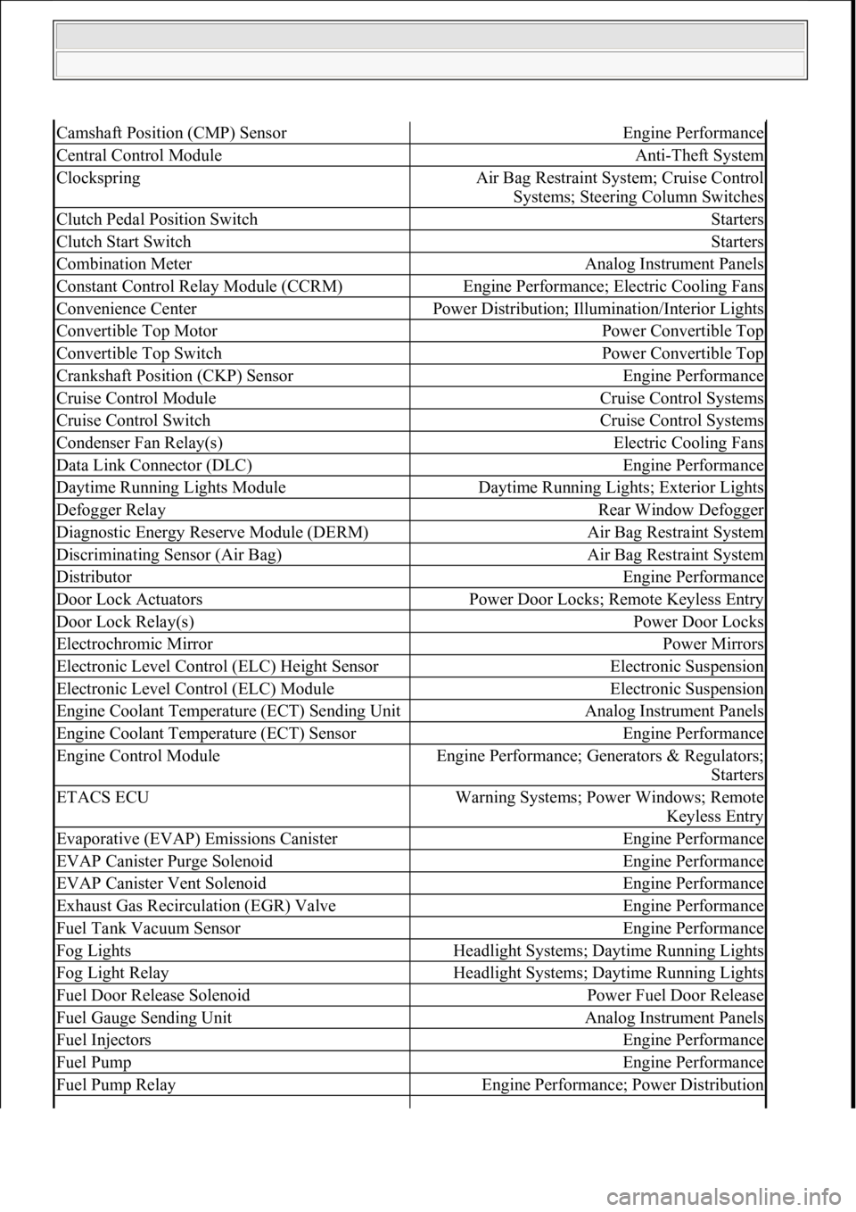
Camshaft Position (CMP) SensorEngine Performance
Central Control ModuleAnti-Theft System
ClockspringAir Bag Restraint System; Cruise Control
Systems; Steering Column Switches
Clutch Pedal Position SwitchStarters
Clutch Start SwitchStarters
Combination MeterAnalog Instrument Panels
Constant Control Relay Module (CCRM)Engine Performance; Electric Cooling Fans
Convenience CenterPower Distribution; Illu mination/Interior Lights
Convertible Top MotorPower Convertible Top
Convertible Top SwitchPower Convertible Top
Crankshaft Position (CKP) SensorEngine Performance
Cruise Control ModuleCruise Control Systems
Cruise Control SwitchCruise Control Systems
Condenser Fan Relay(s)Electric Cooling Fans
Data Link Connector (DLC)Engine Performance
Daytime Running Lights ModuleDaytime Running Lights; Exterior Lights
Defogger RelayRear Window Defogger
Diagnostic Energy Reserve Module (DERM)Air Bag Restraint System
Discriminating Sensor (Air Bag)Air Bag Restraint System
DistributorEngine Performance
Door Lock ActuatorsPower Door Locks; Remote Keyless Entry
Door Lock Relay(s)Power Door Locks
Electrochromic MirrorPower Mirrors
Electronic Level Control (ELC) Height SensorElectronic Suspension
Electronic Level Control (ELC) ModuleElectronic Suspension
Engine Coolant Temper ature (ECT) Sending UnitAnalog Instrument Panels
Engine Coolant Temperature (ECT) SensorEngine Performance
Engine Control ModuleEngine Performance; Ge nerators & Regulators;
Starters
ETACS ECUWarning Systems; Power Windows; Remote Keyless Entry
Evaporative (EVAP) Emissions CanisterEngine Performance
EVAP Canister Purge SolenoidEngine Performance
EVAP Canister Vent SolenoidEngine Performance
Exhaust Gas Recirculation (EGR) ValveEngine Performance
Fuel Tank Vacuum SensorEngine Performance
Fog LightsHeadlight Systems; Daytime Running Lights
Fog Light RelayHeadlight Systems; Daytime Running Lights
Fuel Door Release SolenoidPower Fuel Door Release
Fuel Gauge Sending UnitAnalog Instrument Panels
Fuel InjectorsEngine Performance
Fuel PumpEngine Performance
Fuel Pump RelayEngine Performance; Power Distribution
111
15 ноября 2011 г. 20:18:43Page 6 © 2006 Mitchell Repair Information Company, LLC.
Page 4153 of 4378
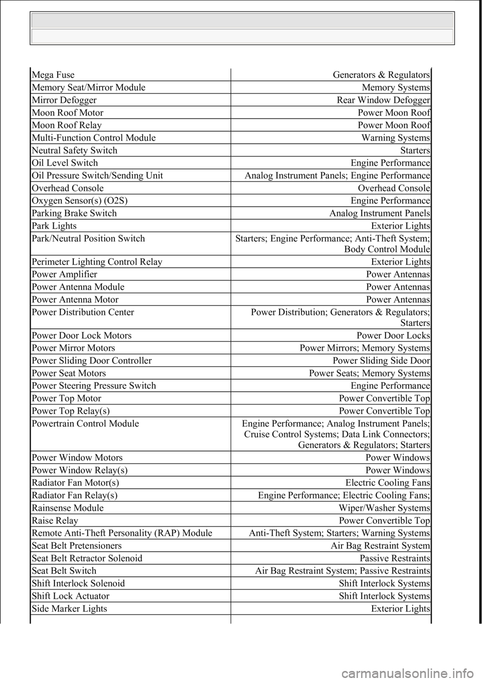
Mega FuseGenerators & Regulators
Memory Seat/Mirror ModuleMemory Systems
Mirror DefoggerRear Window Defogger
Moon Roof MotorPower Moon Roof
Moon Roof RelayPower Moon Roof
Multi-Function Control ModuleWarning Systems
Neutral Safety SwitchStarters
Oil Level SwitchEngine Performance
Oil Pressure Switch/Sending UnitAnalog Instrument Panels; Engine Performance
Overhead ConsoleOverhead Console
Oxygen Sensor(s) (O2S)Engine Performance
Parking Brake SwitchAnalog Instrument Panels
Park LightsExterior Lights
Park/Neutral Position SwitchStarters; Engine Performance; Anti-Theft System;
Body Control Module
Perimeter Lighting Control RelayExterior Lights
Power AmplifierPower Antennas
Power Antenna ModulePower Antennas
Power Antenna MotorPower Antennas
Power Distribution CenterPower Distribution; Gene rators & Regulators;
Starters
Power Door Lock MotorsPower Door Locks
Power Mirror MotorsPower Mirrors; Memory Systems
Power Sliding Door ControllerPower Sliding Side Door
Power Seat MotorsPower Seats; Memory Systems
Power Steering Pressure SwitchEngine Performance
Power Top MotorPower Convertible Top
Power Top Relay(s)Power Convertible Top
Powertrain Control ModuleEngine Performance; Analog Instrument Panels; Cruise Control Systems; Data Link Connectors;
Generators & Regulators; Starters
Power Window MotorsPower Windows
Power Window Relay(s)Power Windows
Radiator Fan Motor(s)Electric Cooling Fans
Radiator Fan Relay(s)Engine Performance; Electric Cooling Fans;
Rainsense ModuleWiper/Washer Systems
Raise RelayPower Convertible Top
Remote Anti-Theft Personality (RAP) ModuleAnti-Theft System; Starters; Warning Systems
Seat Belt PretensionersAir Bag Restraint System
Seat Belt Retractor SolenoidPassive Restraints
Seat Belt SwitchAir Bag Restraint System; Passive Restraints
Shift Interlock SolenoidShift Interlock Systems
Shift Lock ActuatorShift Interlock Systems
Side Marker LightsExterior Lights
111
15 ноября 2011 г. 20:18:43Page 8 © 2006 Mitchell Repair Information Company, LLC.
Page 4208 of 4378
Fig. 53: Trunk, Tailgate, Fuel Door Circuit
WARNING SYSTEMS
2003 Ford Mustang
2003 SYSTEM WIRING DIAGRAMS Ford - Mustang
111
18 ноября 2011 г. 12:45:09Page 54 © 2006 Mitchell Repair Information Company, LLC.