Page 2239 of 4378
5.
CAUTION: The mass air flow (MAF) sensor hot wire sensing element and housing
are calibrated as a unit and must be repaired as a complete assembly. Do not damage
the sensing element (internal to housing) or possible failure to the mass air flow sensor
can occur.
Remove the mass air flow sensor.
�zDisconnect the MAF sensor electrical connector.
�z Remove the bolts and the MAF sensor.
6. To install, reverse the removal procedure. �K�l�j . 2 �b�a
32003 Mustang Workshop Manual
18. 11. 2011file:///C:/Ford/2000 - 2004/tsocache/SHEF_4464/S3B~us~en~ ...
Page 2241 of 4378
REMOVAL AND INSTALLATION
Mass Air Flow (MAF) Sensor —
Mach I
Removal
CAUTION: The mass air flow (MAF) sensor hot wire sensing element and housing are
calibrated as a unit and must be repaired as a complete assembly. Do not damage the sensing
element (internal to housing) or possible failure to the mass air flow sensor may occur
1. Disconnect the battery ground cable. For additional information, refer to Section 414 - 01 .
2. Remove the air cleaner outlet tube. For additional information, refer to Section 303 - 12 .
3. Remove the mass air flow sensor (MAF). �zDisconnect the connector.
�z Remove the four nuts and the MAF sensor.
Installation 1. To install, reverse the removal procedure.
SECTION 303-
14: Electronic Engine Controls 2003 Mustang Workshop Manual �K�l�j . 1 �b�a
22003 Mustang Workshop Manual
18. 11. 2011file:///C:/Ford/2000 - 2004/tsocache/SHEF_4464/S3B~us~en~ ...
Page 2243 of 4378
REMOVAL AND INSTALLATION
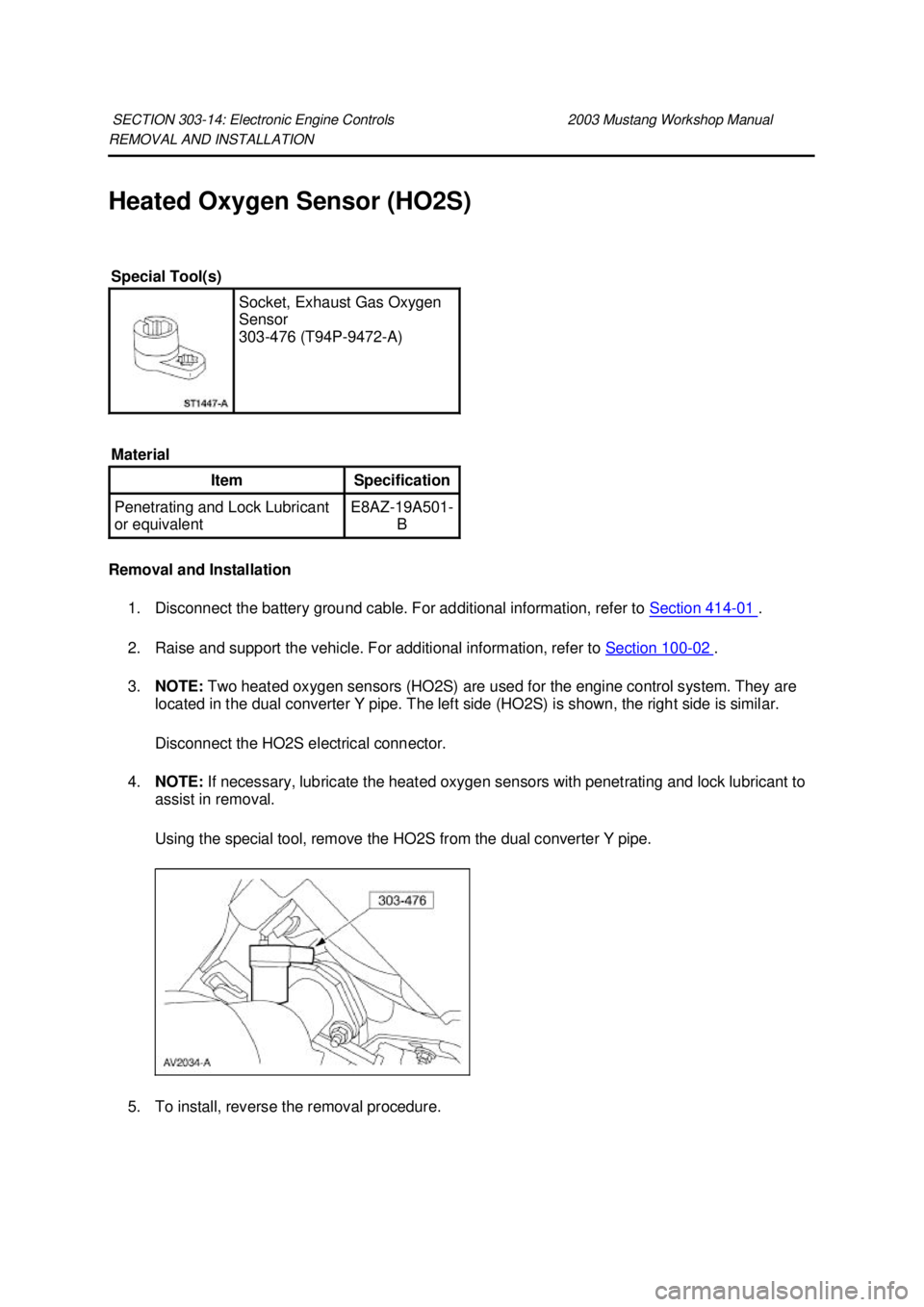
Heated Oxygen Sensor (HO2S)
Removal and Installation
1. Disconnect the battery ground cable. For additional information, refer to Section 414 - 01 .
2. Raise and support the vehicle. For additional information, refer to Section 100 - 02 .
3. NOTE: Two heated oxygen sensors (HO2S) are used for the engine control system. They are
located in the dual converter Y pipe. The left side (HO2S) is shown, the right side is similar.
Disconnect the HO2S electrical connector.
4. NOTE: If necessary, lubricate the heated oxygen sensors with penetrating and lock lubricant to
assist in removal.
Using the special tool, remove the HO2S from the dual converter Y pipe.
5. To install, reverse the removal procedure.
SECTION 303-
14: Electronic Engine Controls 2003 Mustang Workshop Manual Special Tool(s)
Socket, Exhaust Gas Oxygen
Sensor
303-
476 (T94P-9472- A)
Material Item Specification
Penetrating and Lock Lubricant
or equivalent E8AZ-
19A501-
B �K�l�j . 1 �b�a
22003 Mustang Workshop Manual
18. 11. 2011file:///C:/Ford/2000 - 2004/tsocache/SHEF_4464/S3B~us~en~ ...
Page 2245 of 4378
REMOVAL AND INSTALLATION
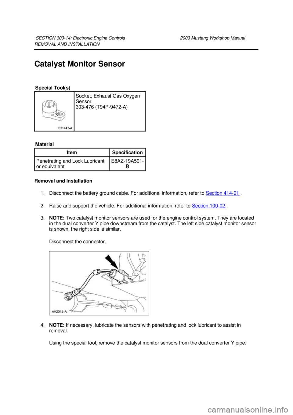
Catalyst Monitor Sensor
Removal and Installation
1. Disconnect the battery ground cable. For additional information, refer to Section 414 - 01 .
2. Raise and support the vehicle. For additional information, refer to Section 100 - 02 .
3. NOTE: Two catalyst monitor sensors are used for the engine control system. They are located
in the dual converter Y pipe downstream from the catalyst. The left side catalyst monitor sensor
is shown, the right side is similar.
Disconnect the connector.
4. NOTE: If necessary, lubricate the sensors with penetrating and lock lubricant to assist in
removal.
Using the special tool, remove the catalyst monitor sensors from the dual converter Y pipe.
SECTION 303-
14: Electronic Engine Controls 2003 Mustang Workshop Manual Special Tool(s)
Socket, Exhaust Gas Oxygen
Sensor
303-
476 (T94P-9472- A)
Material Item Specification
Penetrating and Lock Lubricant
or equivalent E8AZ-
19A501-
B �K�l�j . 1 �b�a
22003 Mustang Workshop Manual
18. 11. 2011file:///C:/Ford/2000 - 2004/tsocache/SHEF_4464/S3B~us~en~ ...
Page 2249 of 4378
REMOVAL AND INSTALLATION
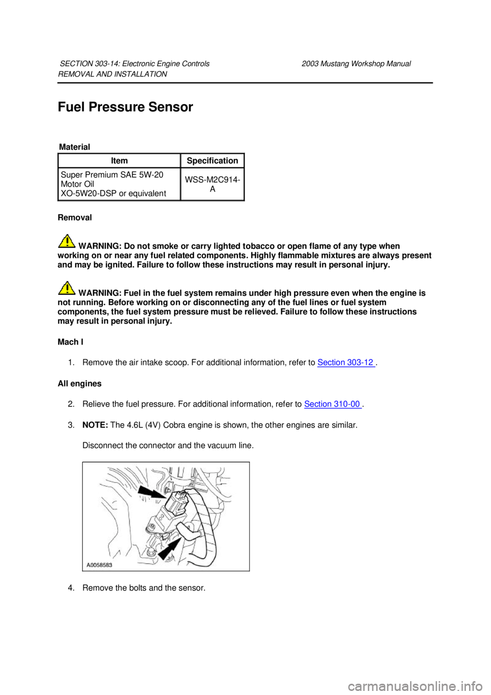
Fuel Pressure Sensor
Removal
WARNING: Do not smoke or carry lighted tobacco or open flame of any type when
working on or near any fuel related components. Highly flammable mixtures are always present
and may be ignited. Failure to follow these instructions may result in personal injury.
WARNING: Fuel in the fuel system remains under high pressure even when the engine is
not running. Before working on or disconnecting any of the fuel lines or fuel system
components, the fuel system pressure must be relieved. Failure to follow these instructions
may result in personal injury.
Mach I
1. Remove the air intake scoop. For additional information, refer to Section 303 - 12 .
All engines 2. Relieve the fuel pressure. For additional information, refer to Section 310 - 00 .
3. NOTE: The 4.6L (4V) Cobra engine is shown, the other engines are similar.
Disconnect the connector and the vacuum line. 4. Remove the bolts and the sensor. SECTION 303-
14: Electronic Engine Controls 2003 Mustang Workshop Manual Material
Item Specification
Super Premium SAE 5W-20
Motor Oil
XO- 5W20- DSP or equivalent WSS-
M2C914-
A �K�l�j . 1 �b�a
22003 Mustang Workshop Manual
18. 11. 2011file:///C:/Ford/2000 - 2004/tsocache/SHEF_4464/S3B~us~en~ ...
Page 2260 of 4378
2-
3 74-80 119-129
3-2 73 117
2-1 32 51
Shift Speeds 3.8L (3:27:1 Axle Ratio) Throttle Position Shift MPH Km/H
Light throttle 1-
2 6-
10 10-16
TP voltage 2-
3 18-22 29-35
1.25 volts 3-
4 28–30 45–48
Closed throttle 4-
3 24-22 39-35
3-2 14-12 22-19
2-1 6-8 10-13
Wide open throttle 1-
2 36-40 58-64
2-3 74-70 119-112
3-2 67 108
2-1 28 45
Shift Speeds 3.8L (3:08:1 Axle Ratio) Throttle Position Shift MPH Km/H
Light throttle 1-
2 6-10 10-16
TP voltage 2-
3 16-20 26-32
1.25 volts 3-
4 38-42 61-68
Closed throttle 4-
3 34-28 55-45
3-2 16-13 26-21
2-1 9-
7 14-
11 Wide open throttle 1-
2 38-45 61-72
2-3 72-76 116-122
3-2 71 114
2-1 31 50
Sensor Resistance Readings Component Resistance (ohms)
SSA 20-
30 SSB 20-
30 EPC 2.48-
5.66 TCC 10-
16 OSS 1,026-
1,194
Selective Thrust Washer No.1 �K�l�j . 3 �b�a
62003 Mustang Workshop Manual
18. 11. 2011file:///C:/Ford/2000 - 2004/tsocache/SHEF_2748/S3B~us~en~ ...
Page 2262 of 4378
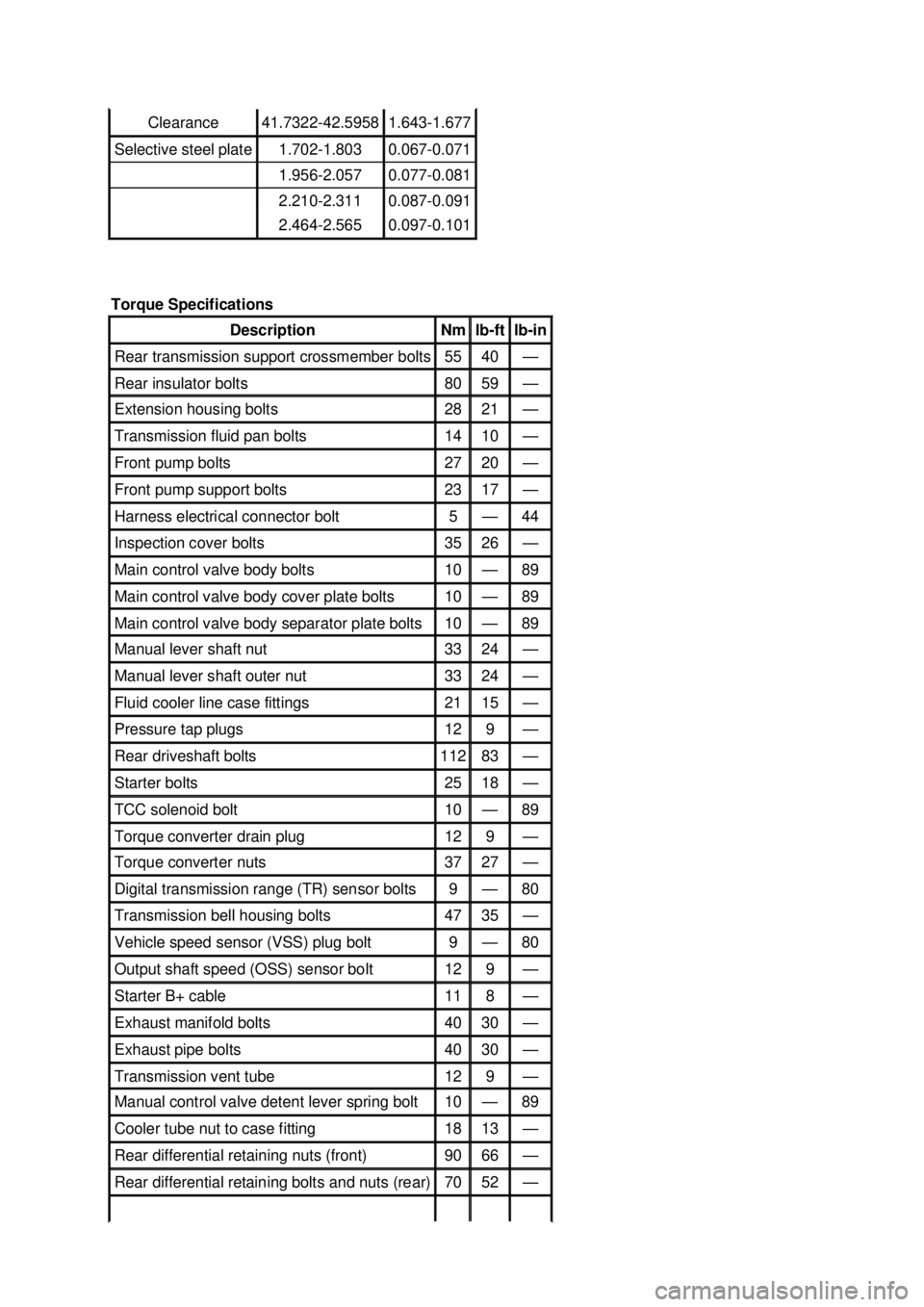
Clearance 41.7322-42.5958 1.643-1.677
Selective steel plate 1.702-
1.803 0.067-0.071
1.956-
2.057 0.077-0.081
2.210-
2.311 0.087-0.091
2.464-
2.565 0.097-0.101
Torque Specifications Description Nm lb-
ft lb-
in Rear transmission support crossmember bolts 55 40 —
Rear insulator bolts 80 59 —
Extension housing bolts 28 21 —
Transmission fluid pan bolts 14 10 —
Front pump bolts 27 20 —
Front pump support bolts 23 17 —
Harness electrical connector bolt 5 — 44
Inspection cover bolts 35 26 —
Main control valve body bolts 10 — 89
Main control valve body cover plate bolts 10 — 89
Main control valve body separator plate bolts 10 — 89
Manual lever shaft nut 33 24 —
Manual lever shaft outer nut 33 24 —
Fluid cooler line case fittings 21 15 —
Pressure tap plugs 12 9 —
Rear driveshaft bolts 112 83 —
Starter bolts 25 18 —
TCC solenoid bolt 10 — 89
Torque converter drain plug 12 9 —
Torque converter nuts 37 27 —
Digital transmission range (TR) sensor bolts 9 — 80
Transmission bell housing bolts 47 35 —
Vehicle speed sensor (VSS) plug bolt 9 — 80
Output shaft speed (OSS) sensor bolt 12 9 —
Starter B+ cable 11 8 —
Exhaust manifold bolts 40 30 —
Exhaust pipe bolts 40 30 —
Transmission vent tube 12 9 —
Manual control valve detent lever spring bolt 10 — 89
Cooler tube nut to case fitting 18 13 —
Rear differential retaining nuts (front) 90 66 —
Rear differential retaining bolts and nuts (rear) 70 52 — �K�l�j . 5 �b�a
62003 Mustang Workshop Manual
18. 11. 2011file:///C:/Ford/2000 - 2004/tsocache/SHEF_2748/S3B~us~en~ ...
Page 2268 of 4378
DESCRIPTION AND OPERATION
Shift Patterns
Upshifts
Transmission upshifting is controlled by the powertrain control module (PCM). The PCM receives
inputs from various engine or vehicle sensors and driver demands to control shift scheduling, shift feel
and torque converter clutch (TCC) operation.
Downshifts
Under certain conditions the transmission will downshift automatically to a lower gear range (without
moving the gearshift lever). There are three categories of automatic downshifts; Coastdown, Torque
Demand and Forced or Kickdown shifts.
Coastdown
The coastdown downshift occurs when the vehicle is coasting down to a stop.
Torque Demand
The torque demand downshift occurs (automatically) during part throttle acceleration when the
demand for torque is greater than the engine can provide at that gear ratio. If applied, the transmission
will disengage the TCC to provide added acceleration.
Kickdown
For maximum acceleration, the driver can force a downshift by pressing the accelerator pedal to the
floor. A forced downshift into a lower gear is possible below calibrated speeds. Specifications for
downshift speeds are subject to variations due to tire size, engine and transmission calibration
requirements.
SECTION 307-
01: Automatic Transaxle/Transmission 2003 Mustang Workshop Manual �K�l�j . 1 �b�a
12003 Mustang Workshop Manual
18. 11. 2011file:///C:/Ford/2000 - 2004/tsocache/SHEF_2748/S3B~us~en~ ...